battery capacity DODGE RAM 2001 Service Repair Manual
[x] Cancel search | Manufacturer: DODGE, Model Year: 2001, Model line: RAM, Model: DODGE RAM 2001Pages: 2889, PDF Size: 68.07 MB
Page 389 of 2889
cial Seal Tool number C-3995-A with handle tool
number C-4171.
(4) Install thermostat into recessed machined
groove on intake manifold (Fig. 25).
(5) Install thermostat housing (Fig. 25).
(6) Install housing-to-intake manifold bolts.
Tighten bolts to 25 N´m (220 in. lbs.) torque.
CAUTION: Housing bolts should be tightened
evenly to prevent damage to housing and to pre-
vent leaks.
(7) Connect the wiring to both sensors.
(8) Install the upper radiator hose and hose clamp
to thermostat housing.
(9) Install support rod.
(10) Fill cooling system (Refer to 7 - COOLING -
STANDARD PROCEDURE).
(11) Connect negative battery cable to battery.
(12) Start and warm engine. Check for leaks.
ENGINE COOLANT
THERMOSTAT - 5.9L DIESEL
DESCRIPTION
CAUTION: Do not operate an engine without a ther-
mostat, except for servicing or testing. An engine
with the thermostat removed will operate in the
radiator bypass mode, causing an overheat condi-
tion.
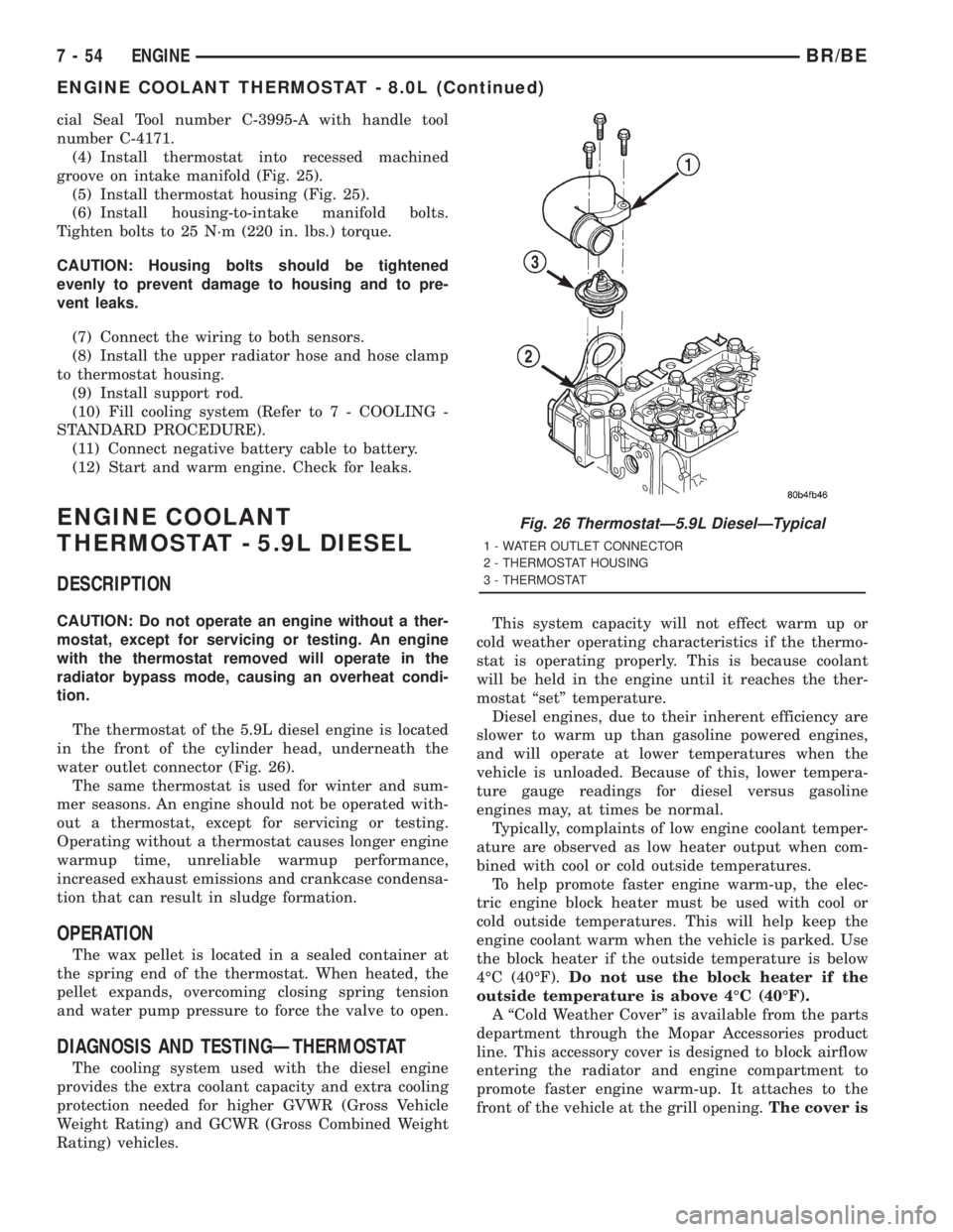
The thermostat of the 5.9L diesel engine is located
in the front of the cylinder head, underneath the
water outlet connector (Fig. 26).
The same thermostat is used for winter and sum-
mer seasons. An engine should not be operated with-
out a thermostat, except for servicing or testing.
Operating without a thermostat causes longer engine
warmup time, unreliable warmup performance,
increased exhaust emissions and crankcase condensa-
tion that can result in sludge formation.
OPERATION
The wax pellet is located in a sealed container at
the spring end of the thermostat. When heated, the
pellet expands, overcoming closing spring tension
and water pump pressure to force the valve to open.
DIAGNOSIS AND TESTINGÐTHERMOSTAT
The cooling system used with the diesel engine
provides the extra coolant capacity and extra cooling
protection needed for higher GVWR (Gross Vehicle
Weight Rating) and GCWR (Gross Combined Weight
Rating) vehicles.This system capacity will not effect warm up or
cold weather operating characteristics if the thermo-
stat is operating properly. This is because coolant
will be held in the engine until it reaches the ther-
mostat ªsetº temperature.
Diesel engines, due to their inherent efficiency are
slower to warm up than gasoline powered engines,
and will operate at lower temperatures when the
vehicle is unloaded. Because of this, lower tempera-
ture gauge readings for diesel versus gasoline
engines may, at times be normal.
Typically, complaints of low engine coolant temper-
ature are observed as low heater output when com-
bined with cool or cold outside temperatures.
To help promote faster engine warm-up, the elec-
tric engine block heater must be used with cool or
cold outside temperatures. This will help keep the
engine coolant warm when the vehicle is parked. Use
the block heater if the outside temperature is below
4ÉC (40ÉF).Do not use the block heater if the
outside temperature is above 4ÉC (40ÉF).
A ªCold Weather Coverº is available from the parts
department through the Mopar Accessories product
line. This accessory cover is designed to block airflow
entering the radiator and engine compartment to
promote faster engine warm-up. It attaches to the
front of the vehicle at the grill opening.The cover is
Fig. 26 ThermostatÐ5.9L DieselÐTypical
1 - WATER OUTLET CONNECTOR
2 - THERMOSTAT HOUSING
3 - THERMOSTAT
7 - 54 ENGINEBR/BE
ENGINE COOLANT THERMOSTAT - 8.0L (Continued)
Page 400 of 2889
(10) Lift radiator straight up and out of engine
compartment. The bottom of the radiator is equipped
with two alignment dowels that fit into holes in the
lower radiator support panel (Fig. 42). Rubber bis-
cuits (insulators) are installed to these dowels. Take
care not to damage cooling fins or tubes on the radi-
ator and air conditioning condenser when removing.
CLEANING
Clean radiator fins are necessary for good heat
transfer. The radiator and air conditioning fins
should be cleaned when an accumulation of debris
has occurred. With the engine cold, apply cold water
and compressed air to the back (engine side) of the
radiator to flush the radiator and/or A/C condenser of
debris.
INSPECTION
Inspect the radiator side tanks for cracks, broken
or missing fittings also inspect the joint where the
tanks seam up to the radiator core for signs of leak-
age and/or deteriorating seals.
Inspect radiator core for corroded, bent or missing
cooling fins. Inspect the core for bent or damaged
cooling tubes.
INSTALLATION
(1) Position fan shroud over the fan blades rear-
ward towards engine.
(2) Install rubber insulators to alignment dowels
at lower part of radiator.
(3) Lower the radiator into position while guiding
the two alignment dowels into lower radiator sup-
port. Different alignment holes are provided in the
lower radiator support for each engine application.
(4) Install two upper radiator mounting bolts.
Tighten bolts to 11 N´m (95 in. lbs.) torque.
(5) Connect both radiator hoses and install hose
clamps.
(6) Connect transmission cooler lines to radiator
tank. Inspect quick connect fittings for debris and
install until an audible ªclickº is heard. Pull apart to
verify connection.
(7) Install windshield washer reservoir tank.
(8) Position fan shroud to flanges on sides of radi-
ator. Install fan shroud mounting bolts (Fig. 41).
Tighten bolts to 6 N´m (50 in. lbs.) torque.
(9) Install metal clips to top of fan shroud.
(10) Install coolant reserve/overflow tank hose to
radiator filler neck nipple.
(11) Install coolant reserve/overflow tank to fan
shroud (fits into T-slots on shroud).
(12) Install battery negative cables.
(13) Install positive battery cable to top of radia-
tor. Tighten radiator-to-battery cable mounting nuts.
(14) Position heater controls tofull heatposition.(15) Fill cooling system with coolant (Refer to 7 -
COOLING - STANDARD PROCEDURE).
(16) Operate engine until it reaches normal tem-
perature. Check cooling system and automatic trans-
mission (if equipped) fluid levels.
RADIATOR PRESSURE CAP
DESCRIPTION
Radiators are equipped with a pressure cap, which
releases pressure at some point within a range of
97-124 kPa (14-18 psi). The pressure relief point (in
pounds) is engraved on top of cap.
The cooling system will operate at pressures
slightly above atmospheric pressure. This results in a
higher coolant boiling point allowing increased radi-
ator cooling capacity.
A rubber gasket seals radiator filler neck to pre-
vent leakage. This is done to keep system under
pressure. It also maintains vacuum during coolant
cool-down allowing coolant to return from reserve/
overflow tank.
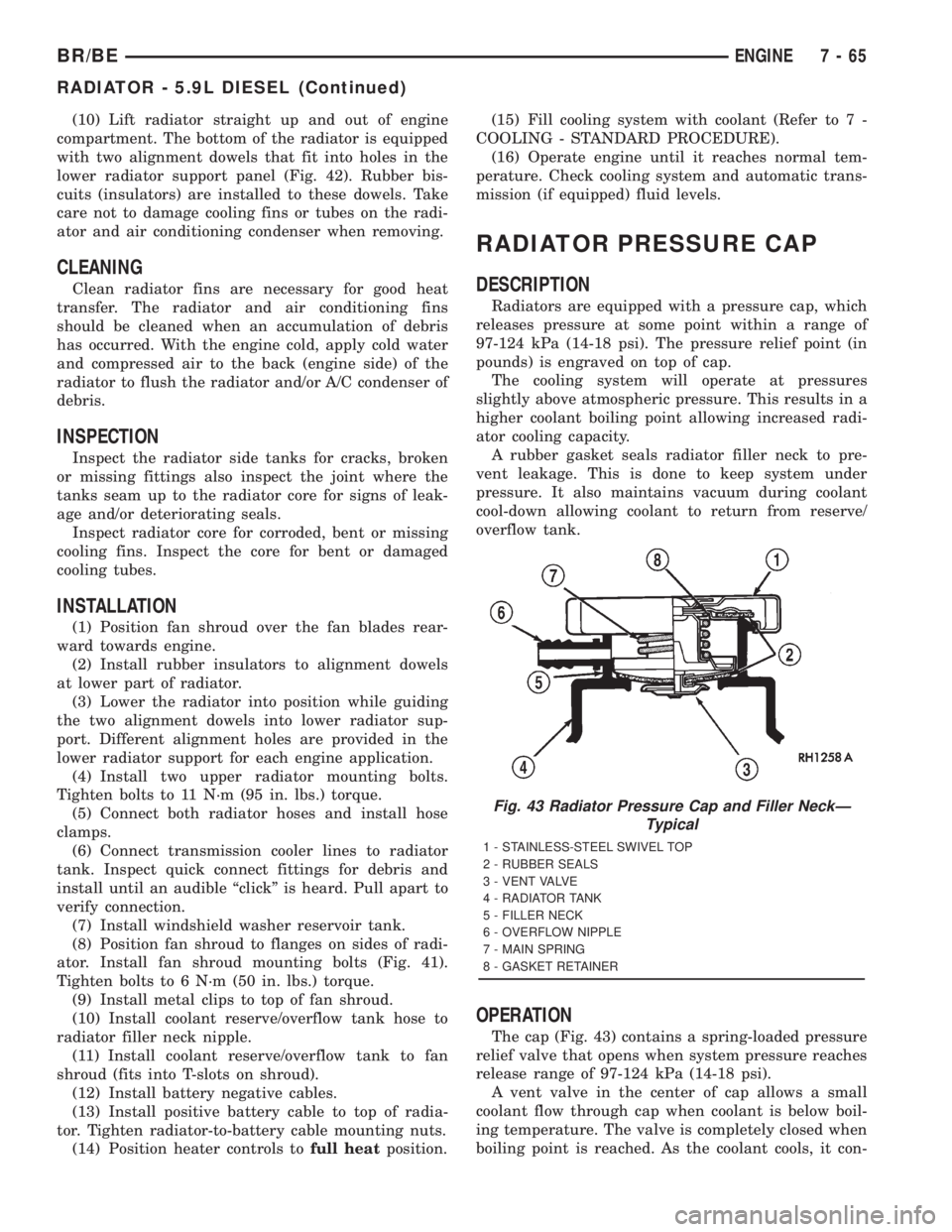
OPERATION
The cap (Fig. 43) contains a spring-loaded pressure
relief valve that opens when system pressure reaches
release range of 97-124 kPa (14-18 psi).
A vent valve in the center of cap allows a small
coolant flow through cap when coolant is below boil-
ing temperature. The valve is completely closed when
boiling point is reached. As the coolant cools, it con-
Fig. 43 Radiator Pressure Cap and Filler NeckÐ
Typical
1 - STAINLESS-STEEL SWIVEL TOP
2 - RUBBER SEALS
3 - VENT VALVE
4 - RADIATOR TANK
5 - FILLER NECK
6 - OVERFLOW NIPPLE
7 - MAIN SPRING
8 - GASKET RETAINER
BR/BEENGINE 7 - 65
RADIATOR - 5.9L DIESEL (Continued)
Page 474 of 2889
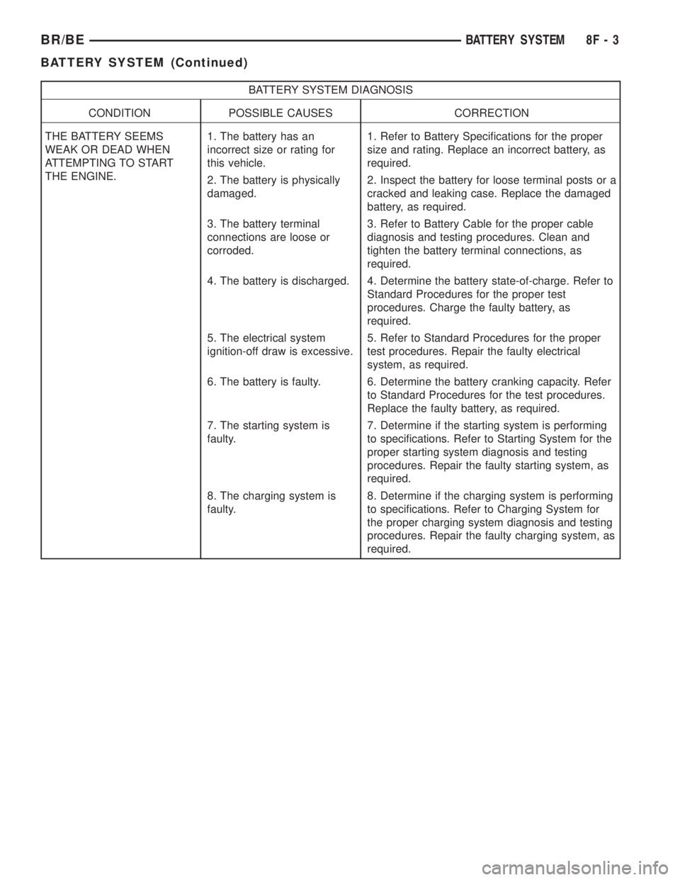
BATTERY SYSTEM DIAGNOSIS
CONDITION POSSIBLE CAUSES CORRECTION
THE BATTERY SEEMS
WEAK OR DEAD WHEN
ATTEMPTING TO START
THE ENGINE.1. The battery has an
incorrect size or rating for
this vehicle.1. Refer to Battery Specifications for the proper
size and rating. Replace an incorrect battery, as
required.
2. The battery is physically
damaged.2. Inspect the battery for loose terminal posts or a
cracked and leaking case. Replace the damaged
battery, as required.
3. The battery terminal
connections are loose or
corroded.3. Refer to Battery Cable for the proper cable
diagnosis and testing procedures. Clean and
tighten the battery terminal connections, as
required.
4. The battery is discharged. 4. Determine the battery state-of-charge. Refer to
Standard Procedures for the proper test
procedures. Charge the faulty battery, as
required.
5. The electrical system
ignition-off draw is excessive.5. Refer to Standard Procedures for the proper
test procedures. Repair the faulty electrical
system, as required.
6. The battery is faulty. 6. Determine the battery cranking capacity. Refer
to Standard Procedures for the test procedures.
Replace the faulty battery, as required.
7. The starting system is
faulty.7. Determine if the starting system is performing
to specifications. Refer to Starting System for the
proper starting system diagnosis and testing
procedures. Repair the faulty starting system, as
required.
8. The charging system is
faulty.8. Determine if the charging system is performing
to specifications. Refer to Charging System for
the proper charging system diagnosis and testing
procedures. Repair the faulty charging system, as
required.
BR/BEBATTERY SYSTEM 8F - 3
BATTERY SYSTEM (Continued)
Page 475 of 2889
BATTERY SYSTEM DIAGNOSIS
CONDITION POSSIBLE CAUSES CORRECTION
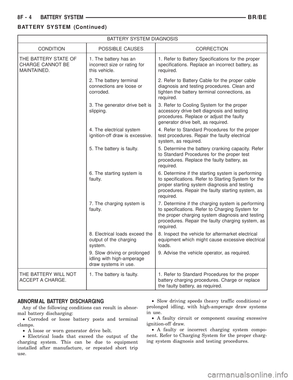
THE BATTERY STATE OF
CHARGE CANNOT BE
MAINTAINED.1. The battery has an
incorrect size or rating for
this vehicle.1. Refer to Battery Specifications for the proper
specifications. Replace an incorrect battery, as
required.
2. The battery terminal
connections are loose or
corroded.2. Refer to Battery Cable for the proper cable
diagnosis and testing procedures. Clean and
tighten the battery terminal connections, as
required.
3. The generator drive belt is
slipping.3. Refer to Cooling System for the proper
accessory drive belt diagnosis and testing
procedures. Replace or adjust the faulty
generator drive belt, as required.
4. The electrical system
ignition-off draw is excessive.4. Refer to Standard Procedures for the proper
test procedures. Repair the faulty electrical
system, as required.
5. The battery is faulty. 5. Determine the battery cranking capacity. Refer
to Standard Procedures for the proper test
procedures. Replace the faulty battery, as
required.
6. The starting system is
faulty.6. Determine if the starting system is performing
to specifications. Refer to Starting System for the
proper starting system diagnosis and testing
procedures. Repair the faulty starting system, as
required.
7. The charging system is
faulty.7. Determine if the charging system is performing
to specifications. Refer to Charging System for
the proper charging system diagnosis and testing
procedures. Repair the faulty charging system, as
required.
8. Electrical loads exceed the
output of the charging
system.8. Inspect the vehicle for aftermarket electrical
equipment which might cause excessive electrical
loads.
9. Slow driving or prolonged
idling with high-amperage
draw systems in use.9. Advise the vehicle operator, as required.
THE BATTERY WILL NOT
ACCEPT A CHARGE.1. The battery is faulty. 1. Refer to Standard Procedures for the proper
battery charging procedures. Charge or replace
the faulty battery, as required.
ABNORMAL BATTERY DISCHARGING
Any of the following conditions can result in abnor-
mal battery discharging:
²Corroded or loose battery posts and terminal
clamps.
²A loose or worn generator drive belt.
²Electrical loads that exceed the output of the
charging system. This can be due to equipment
installed after manufacture, or repeated short trip
use.²Slow driving speeds (heavy traffic conditions) or
prolonged idling, with high-amperage draw systems
in use.
²A faulty circuit or component causing excessive
ignition-off draw.
²A faulty or incorrect charging system compo-
nent. Refer to Charging System for the proper charg-
ing system diagnosis and testing procedures.
8F - 4 BATTERY SYSTEMBR/BE
BATTERY SYSTEM (Continued)
Page 477 of 2889
(2) Inspect the battery tray and battery holddown
hardware for damage. Replace any damaged parts.
(3) Slide the thermal guard off of the battery case,
if equipped. Inspect the battery case for cracks or
other damage that could result in electrolyte leaks.
Also, check the battery terminal posts for looseness.
Batteries with damaged cases or loose terminal posts
must be replaced.
(4) Inspect the battery thermal guard for tears,
cracks, deformation or other damage. Replace any
battery thermal guard that has been damaged.
(5) Inspect the battery built-in test indicator sight
glass for an indication of the battery condition. If the
battery is discharged, charge as required. Refer to
Standard Procedures for the proper battery built-in
indicator test procedures. Also refer to Standard Pro-
cedures for the proper battery charging procedures.
SPECIFICATIONS
BATTERY
Battery Classifications and Ratings
Part NumberBCI Group Size
ClassificationCold
Cranking
AmperageReserve
CapacityAmpere-HoursLoad Test
Amperage
56028375AA 27 600 120 Minutes 66 300
56028376AA 27 750 150 Minutes 75 375
BATTERY
DESCRIPTION
A large capacity, low-maintenance storage battery
(Fig. 4) is standard factory-installed equipment on
this model. Refer to Battery Specifications for the
proper specifications of the factory-installed batteries
available on this model. Male post type terminals
made of a soft lead material protrude from the top of
the molded plastic battery case to provide the means
for connecting the battery to the vehicle electrical
system. The battery positive terminal post is physi-
cally larger in diameter than the negative terminalpost to ensure proper battery connection. The letters
POSandNEGare also molded into the top of the
battery case adjacent to their respective positive and
negative terminal posts for identification confirma-
tion. Refer to Battery Cables for more information on
the battery cables that connect the battery to the
vehicle electrical system.
The battery is made up of six individual cells that
are connected in series. Each cell contains positively
charged plate groups that are connected with lead
straps to the positive terminal post, and negatively
charged plate groups that are connected with lead
straps to the negative terminal post. Each plate con-
sists of a stiff mesh framework or grid coated with
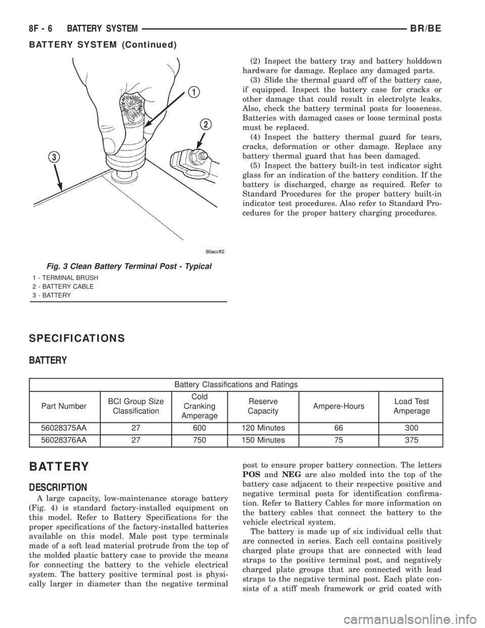
Fig. 3 Clean Battery Terminal Post - Typical
1 - TERMINAL BRUSH
2 - BATTERY CABLE
3 - BATTERY
8F - 6 BATTERY SYSTEMBR/BE
BATTERY SYSTEM (Continued)
Page 479 of 2889
WARNING: IF THE BATTERY SHOWS SIGNS OF
FREEZING, LEAKING OR LOOSE POSTS, DO NOT
TEST, ASSIST-BOOST, OR CHARGE. THE BATTERY
MAY ARC INTERNALLY AND EXPLODE. PERSONAL
INJURY AND/OR VEHICLE DAMAGE MAY RESULT.
WARNING: EXPLOSIVE HYDROGEN GAS FORMS IN
AND AROUND THE BATTERY. DO NOT SMOKE,
USE FLAME, OR CREATE SPARKS NEAR THE BAT-
TERY. PERSONAL INJURY AND/OR VEHICLE DAM-
AGE MAY RESULT.
WARNING: THE BATTERY CONTAINS SULFURIC
ACID, WHICH IS POISONOUS AND CAUSTIC. AVOID
CONTACT WITH THE SKIN, EYES, OR CLOTHING.
IN THE EVENT OF CONTACT, FLUSH WITH WATER
AND CALL A PHYSICIAN IMMEDIATELY. KEEP OUT
OF THE REACH OF CHILDREN.
WARNING: IF THE BATTERY IS EQUIPPED WITH
REMOVABLE CELL CAPS, BE CERTAIN THAT EACH
OF THE CELL CAPS ARE IN PLACE AND TIGHT
BEFORE THE BATTERY IS RETURNED TO SER-
VICE. PERSONAL INJURY AND/OR VEHICLE DAM-
AGE MAY RESULT FROM LOOSE OR MISSING
CELL CAPS.
The condition of a battery is determined by two cri-
teria:
²State-Of-Charge- This can be determined by
checking the specific gravity of the battery electrolyte
(built-in indicator test or hydrometer test), or by
checking the battery voltage (open-circuit voltage
test).
²Cranking Capacity- This can be determined
by performing a battery load test, which measures
the ability of the battery to supply high-amperage
current.
First, determine the battery state-of-charge. This
can be done in one of three ways. If the battery has a
built-in test indicator, perform the built-in indicator
test to determine the state-of-charge. If the battery
has no built-in test indicator but does have remov-
able cell caps, perform the hydrometer test to deter-
mine the state-of-charge. If the battery cell caps are
not removable, or a hydrometer is not available, per-
form the open-circuit voltage test to determine the
state-of-charge.
Second, determine the battery cranking capacity by
performing a load test. The battery must be charged
before proceeding with a load test if:
²The battery built-in test indicator has a black or
dark color visible.
²The temperature corrected specific gravity of the
battery electrolyte is less than 1.235.²The battery open-circuit voltage is less than 12.4
volts.
A battery that will not accept a charge is faulty,
and must be replaced. Further testing is not
required. A fully-charged battery must be load tested
to determine its cranking capacity. A battery that is
fully-charged, but does not pass the load test, is
faulty and must be replaced.
NOTE: Completely discharged batteries may take
several hours to accept a charge. Refer to Standard
Procedures for the proper battery charging proce-
dures.
A battery is fully-charged when:
²All battery cells are gassing freely during charg-
ing.
²A green color is visible in the sight glass of the
battery built-in test indicator.
²Three corrected specific gravity tests, taken at
one-hour intervals, indicate no increase in the spe-
cific gravity of the battery electrolyte.
²Open-circuit voltage of the battery is 12.4 volts
or greater.
STANDARD PROCEDURE - CHECKING BATTERY
ELECTROLYTE LEVEL
The following procedure can be used to check the
electrolyte level in the battery.
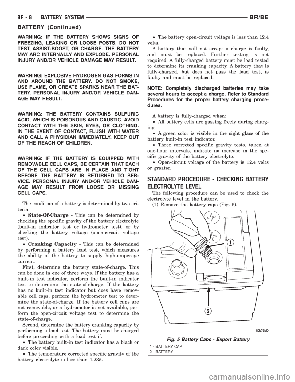
(1) Remove the battery caps (Fig. 5).
Fig. 5 Battery Caps - Export Battery
1 - BATTERY CAP
2 - BATTERY
8F - 8 BATTERY SYSTEMBR/BE
BATTERY (Continued)
Page 481 of 2889
NOTE: Models equipped with the diesel engine
option are equipped with two 12-volt batteries, con-
nected in parallel (positive-to-positive and negative-
to-negative). In order to ensure proper charging of
each battery, these batteries MUST be disconnected
from each other, as well as from the vehicle electri-
cal system, while being charged.
Some battery chargers are equipped with polarity-
sensing circuitry. This circuitry protects the battery
charger and the battery from being damaged if they
are improperly connected. If the battery state-of-
charge is too low for the polarity-sensing circuitry to
detect, the battery charger will not operate. This
makes it appear that the battery will not accept
charging current. See the instructions provided by
the manufacturer of the battery charger for details
on how to bypass the polarity-sensing circuitry.
After the battery has been charged to 12.4 volts or
greater, perform a load test to determine the battery
cranking capacity. Refer to Standard Procedures for
the proper battery load test procedures. If the battery
will endure a load test, return the battery to service.
If the battery will not endure a load test, it is faulty
and must be replaced.
Clean and inspect the battery hold downs, tray,
terminals, posts, and top before completing battery
service. Refer to Battery System Cleaning for the
proper battery system cleaning procedures, and Bat-
tery System Inspection for the proper battery system
inspection procedures.
CHARGING A COMPLETELY DISCHARGED
BATTERY
The following procedure should be used to recharge
a completely discharged battery. Unless this proce-
dure is properly followed, a good battery may be
needlessly replaced.
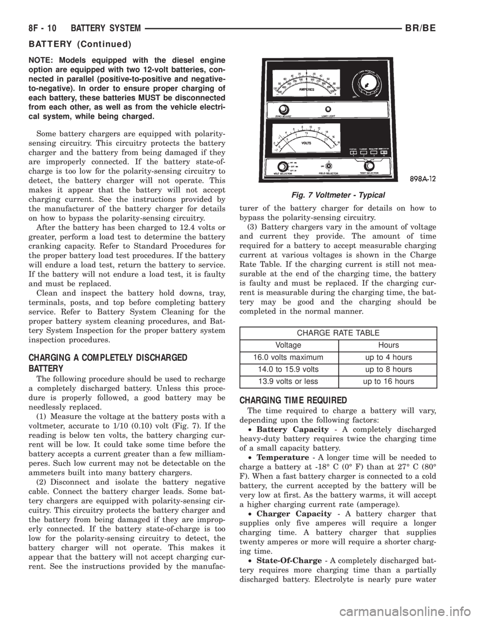
(1) Measure the voltage at the battery posts with a
voltmeter, accurate to 1/10 (0.10) volt (Fig. 7). If the
reading is below ten volts, the battery charging cur-
rent will be low. It could take some time before the
battery accepts a current greater than a few milliam-
peres. Such low current may not be detectable on the
ammeters built into many battery chargers.
(2) Disconnect and isolate the battery negative
cable. Connect the battery charger leads. Some bat-
tery chargers are equipped with polarity-sensing cir-
cuitry. This circuitry protects the battery charger and
the battery from being damaged if they are improp-
erly connected. If the battery state-of-charge is too
low for the polarity-sensing circuitry to detect, the
battery charger will not operate. This makes it
appear that the battery will not accept charging cur-
rent. See the instructions provided by the manufac-turer of the battery charger for details on how to
bypass the polarity-sensing circuitry.
(3) Battery chargers vary in the amount of voltage
and current they provide. The amount of time
required for a battery to accept measurable charging
current at various voltages is shown in the Charge
Rate Table. If the charging current is still not mea-
surable at the end of the charging time, the battery
is faulty and must be replaced. If the charging cur-
rent is measurable during the charging time, the bat-
tery may be good and the charging should be
completed in the normal manner.
CHARGE RATE TABLE
Voltage Hours
16.0 volts maximum up to 4 hours
14.0 to 15.9 volts up to 8 hours
13.9 volts or less up to 16 hours
CHARGING TIME REQUIRED
The time required to charge a battery will vary,
depending upon the following factors:
²Battery Capacity- A completely discharged
heavy-duty battery requires twice the charging time
of a small capacity battery.
²Temperature- A longer time will be needed to
charge a battery at -18É C (0É F) than at 27É C (80É
F). When a fast battery charger is connected to a cold
battery, the current accepted by the battery will be
very low at first. As the battery warms, it will accept
a higher charging current rate (amperage).
²Charger Capacity- A battery charger that
supplies only five amperes will require a longer
charging time. A battery charger that supplies
twenty amperes or more will require a shorter charg-
ing time.
²State-Of-Charge- A completely discharged bat-
tery requires more charging time than a partially
discharged battery. Electrolyte is nearly pure water
Fig. 7 Voltmeter - Typical
8F - 10 BATTERY SYSTEMBR/BE
BATTERY (Continued)
Page 482 of 2889
in a completely discharged battery. At first, the
charging current (amperage) will be low. As the bat-
tery charges, the specific gravity of the electrolyte
will gradually rise.
The Battery Charging Time Table gives an indica-
tion of the time required to charge a typical battery
at room temperature based upon the battery state-of-
charge and the charger capacity.
BATTERY CHARGING TIME TABLE
Charging
Amperage5 Amps10
Amps20 Amps
Open Circuit
VoltageHours Charging @ 21É C
(70É F)
12.25 to 12.49 6 hours 3 hours 1.5
hours
12.00 to 12.24 10 hours 5 hours 2.5
hours
10.00 to 11.99 14 hours 7 hours 3.5
hours
Below 10.00 18 hours 9 hours 4.5
hours
STANDARD PROCEDURE - BUILT-IN
INDICATOR TEST
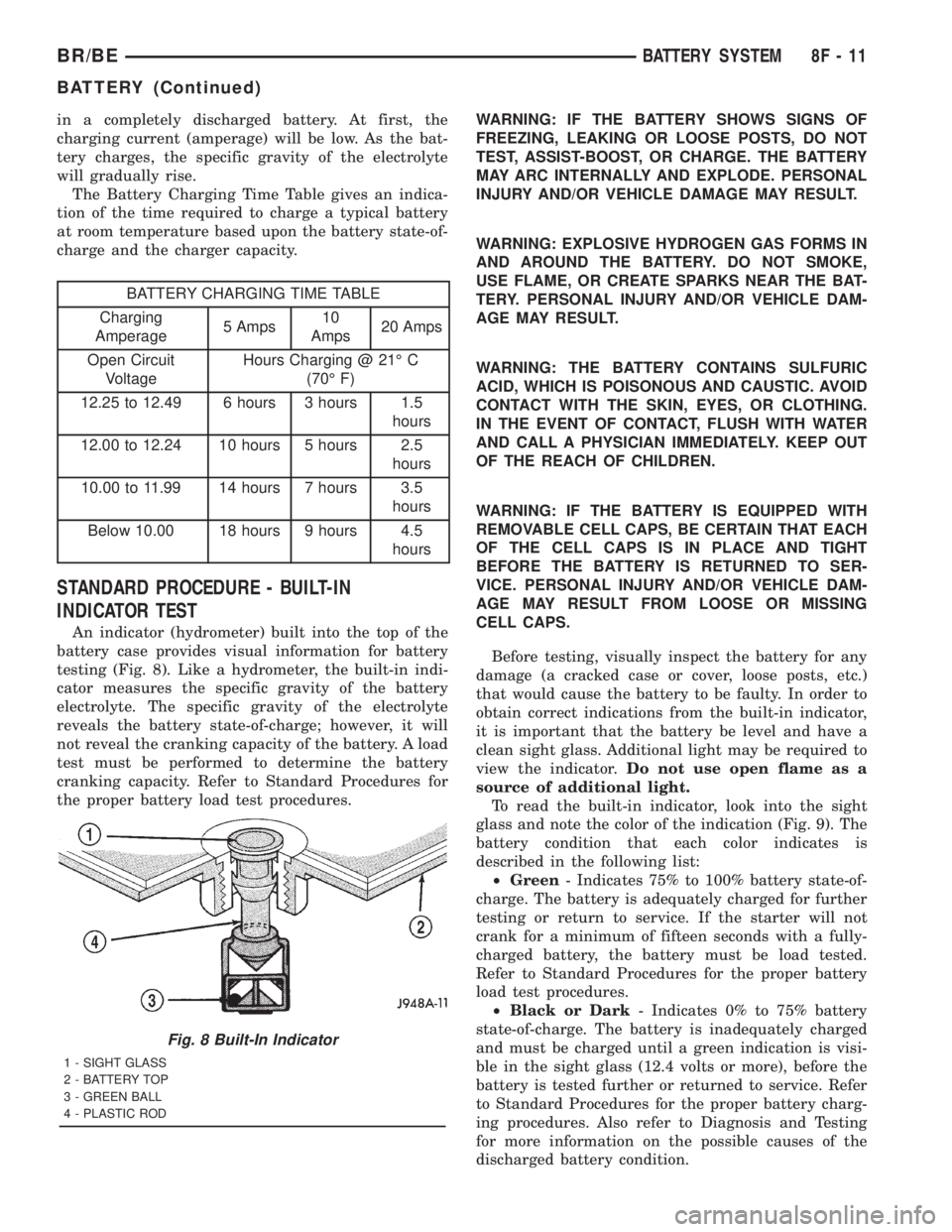
An indicator (hydrometer) built into the top of the
battery case provides visual information for battery
testing (Fig. 8). Like a hydrometer, the built-in indi-
cator measures the specific gravity of the battery
electrolyte. The specific gravity of the electrolyte
reveals the battery state-of-charge; however, it will
not reveal the cranking capacity of the battery. A load
test must be performed to determine the battery
cranking capacity. Refer to Standard Procedures for
the proper battery load test procedures.WARNING: IF THE BATTERY SHOWS SIGNS OF
FREEZING, LEAKING OR LOOSE POSTS, DO NOT
TEST, ASSIST-BOOST, OR CHARGE. THE BATTERY
MAY ARC INTERNALLY AND EXPLODE. PERSONAL
INJURY AND/OR VEHICLE DAMAGE MAY RESULT.
WARNING: EXPLOSIVE HYDROGEN GAS FORMS IN
AND AROUND THE BATTERY. DO NOT SMOKE,
USE FLAME, OR CREATE SPARKS NEAR THE BAT-
TERY. PERSONAL INJURY AND/OR VEHICLE DAM-
AGE MAY RESULT.
WARNING: THE BATTERY CONTAINS SULFURIC
ACID, WHICH IS POISONOUS AND CAUSTIC. AVOID
CONTACT WITH THE SKIN, EYES, OR CLOTHING.
IN THE EVENT OF CONTACT, FLUSH WITH WATER
AND CALL A PHYSICIAN IMMEDIATELY. KEEP OUT
OF THE REACH OF CHILDREN.
WARNING: IF THE BATTERY IS EQUIPPED WITH
REMOVABLE CELL CAPS, BE CERTAIN THAT EACH
OF THE CELL CAPS IS IN PLACE AND TIGHT
BEFORE THE BATTERY IS RETURNED TO SER-
VICE. PERSONAL INJURY AND/OR VEHICLE DAM-
AGE MAY RESULT FROM LOOSE OR MISSING
CELL CAPS.
Before testing, visually inspect the battery for any
damage (a cracked case or cover, loose posts, etc.)
that would cause the battery to be faulty. In order to
obtain correct indications from the built-in indicator,
it is important that the battery be level and have a
clean sight glass. Additional light may be required to
view the indicator.Do not use open flame as a
source of additional light.
To read the built-in indicator, look into the sight
glass and note the color of the indication (Fig. 9). The
battery condition that each color indicates is
described in the following list:
²Green- Indicates 75% to 100% battery state-of-
charge. The battery is adequately charged for further
testing or return to service. If the starter will not
crank for a minimum of fifteen seconds with a fully-
charged battery, the battery must be load tested.
Refer to Standard Procedures for the proper battery
load test procedures.
²Black or Dark- Indicates 0% to 75% battery
state-of-charge. The battery is inadequately charged
and must be charged until a green indication is visi-
ble in the sight glass (12.4 volts or more), before the
battery is tested further or returned to service. Refer
to Standard Procedures for the proper battery charg-
ing procedures. Also refer to Diagnosis and Testing
for more information on the possible causes of the
discharged battery condition.
Fig. 8 Built-In Indicator
1 - SIGHT GLASS
2 - BATTERY TOP
3 - GREEN BALL
4 - PLASTIC ROD
BR/BEBATTERY SYSTEM 8F - 11
BATTERY (Continued)
Page 484 of 2889
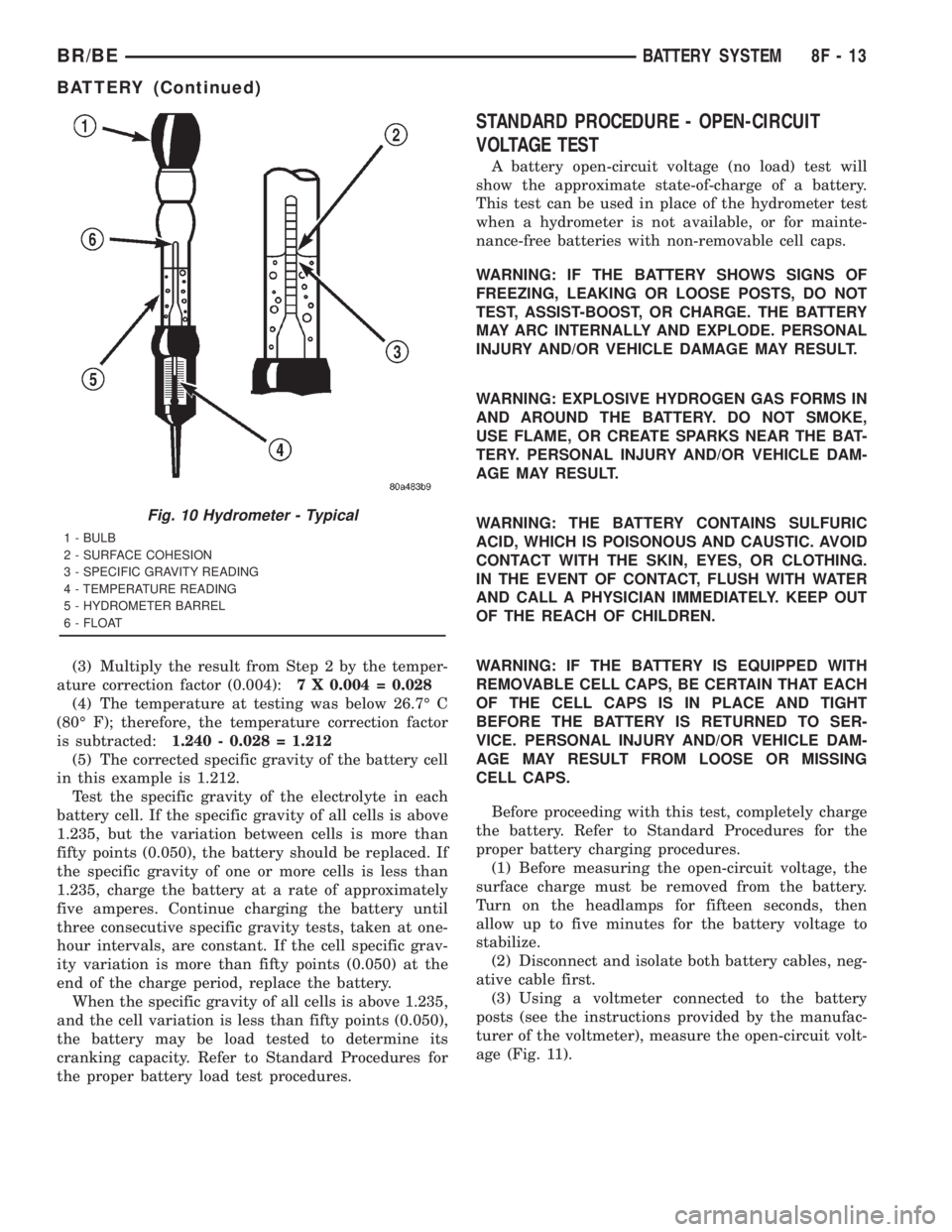
(3) Multiply the result from Step 2 by the temper-
ature correction factor (0.004):7 X 0.004 = 0.028
(4) The temperature at testing was below 26.7É C
(80É F); therefore, the temperature correction factor
is subtracted:1.240 - 0.028 = 1.212
(5) The corrected specific gravity of the battery cell
in this example is 1.212.
Test the specific gravity of the electrolyte in each
battery cell. If the specific gravity of all cells is above
1.235, but the variation between cells is more than
fifty points (0.050), the battery should be replaced. If
the specific gravity of one or more cells is less than
1.235, charge the battery at a rate of approximately
five amperes. Continue charging the battery until
three consecutive specific gravity tests, taken at one-
hour intervals, are constant. If the cell specific grav-
ity variation is more than fifty points (0.050) at the
end of the charge period, replace the battery.
When the specific gravity of all cells is above 1.235,
and the cell variation is less than fifty points (0.050),
the battery may be load tested to determine its
cranking capacity. Refer to Standard Procedures for
the proper battery load test procedures.
STANDARD PROCEDURE - OPEN-CIRCUIT
VOLTAGE TEST
A battery open-circuit voltage (no load) test will
show the approximate state-of-charge of a battery.
This test can be used in place of the hydrometer test
when a hydrometer is not available, or for mainte-
nance-free batteries with non-removable cell caps.
WARNING: IF THE BATTERY SHOWS SIGNS OF
FREEZING, LEAKING OR LOOSE POSTS, DO NOT
TEST, ASSIST-BOOST, OR CHARGE. THE BATTERY
MAY ARC INTERNALLY AND EXPLODE. PERSONAL
INJURY AND/OR VEHICLE DAMAGE MAY RESULT.
WARNING: EXPLOSIVE HYDROGEN GAS FORMS IN
AND AROUND THE BATTERY. DO NOT SMOKE,
USE FLAME, OR CREATE SPARKS NEAR THE BAT-
TERY. PERSONAL INJURY AND/OR VEHICLE DAM-
AGE MAY RESULT.
WARNING: THE BATTERY CONTAINS SULFURIC
ACID, WHICH IS POISONOUS AND CAUSTIC. AVOID
CONTACT WITH THE SKIN, EYES, OR CLOTHING.
IN THE EVENT OF CONTACT, FLUSH WITH WATER
AND CALL A PHYSICIAN IMMEDIATELY. KEEP OUT
OF THE REACH OF CHILDREN.
WARNING: IF THE BATTERY IS EQUIPPED WITH
REMOVABLE CELL CAPS, BE CERTAIN THAT EACH
OF THE CELL CAPS IS IN PLACE AND TIGHT
BEFORE THE BATTERY IS RETURNED TO SER-
VICE. PERSONAL INJURY AND/OR VEHICLE DAM-
AGE MAY RESULT FROM LOOSE OR MISSING
CELL CAPS.
Before proceeding with this test, completely charge
the battery. Refer to Standard Procedures for the
proper battery charging procedures.
(1) Before measuring the open-circuit voltage, the
surface charge must be removed from the battery.
Turn on the headlamps for fifteen seconds, then
allow up to five minutes for the battery voltage to
stabilize.
(2) Disconnect and isolate both battery cables, neg-
ative cable first.
(3) Using a voltmeter connected to the battery
posts (see the instructions provided by the manufac-
turer of the voltmeter), measure the open-circuit volt-
age (Fig. 11).
Fig. 10 Hydrometer - Typical
1 - BULB
2 - SURFACE COHESION
3 - SPECIFIC GRAVITY READING
4 - TEMPERATURE READING
5 - HYDROMETER BARREL
6 - FLOAT
BR/BEBATTERY SYSTEM 8F - 13
BATTERY (Continued)
Page 485 of 2889
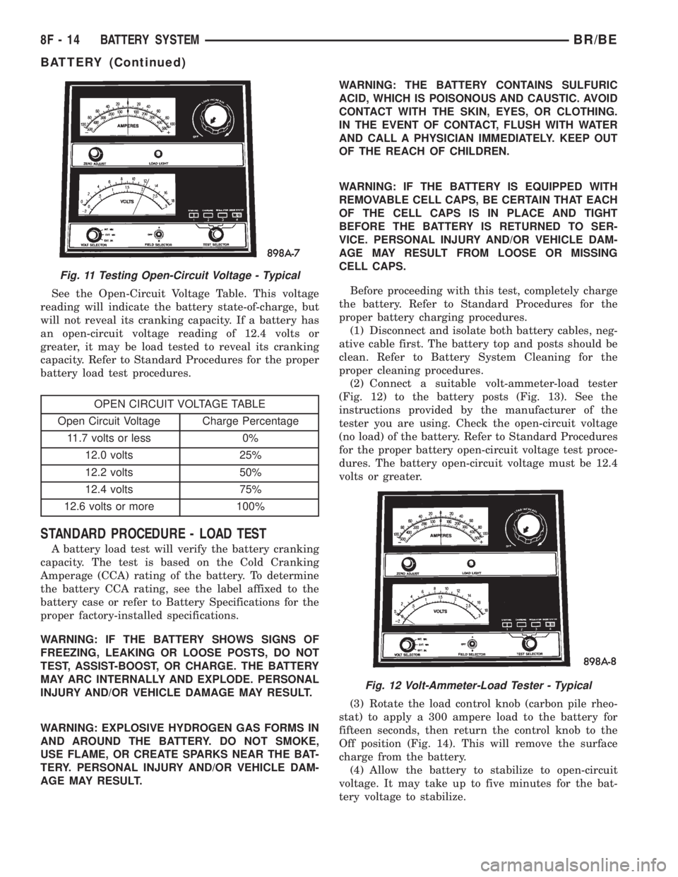
See the Open-Circuit Voltage Table. This voltage
reading will indicate the battery state-of-charge, but
will not reveal its cranking capacity. If a battery has
an open-circuit voltage reading of 12.4 volts or
greater, it may be load tested to reveal its cranking
capacity. Refer to Standard Procedures for the proper
battery load test procedures.
OPEN CIRCUIT VOLTAGE TABLE
Open Circuit Voltage Charge Percentage
11.7 volts or less 0%
12.0 volts 25%
12.2 volts 50%
12.4 volts 75%
12.6 volts or more 100%
STANDARD PROCEDURE - LOAD TEST
A battery load test will verify the battery cranking
capacity. The test is based on the Cold Cranking
Amperage (CCA) rating of the battery. To determine
the battery CCA rating, see the label affixed to the
battery case or refer to Battery Specifications for the
proper factory-installed specifications.
WARNING: IF THE BATTERY SHOWS SIGNS OF
FREEZING, LEAKING OR LOOSE POSTS, DO NOT
TEST, ASSIST-BOOST, OR CHARGE. THE BATTERY
MAY ARC INTERNALLY AND EXPLODE. PERSONAL
INJURY AND/OR VEHICLE DAMAGE MAY RESULT.
WARNING: EXPLOSIVE HYDROGEN GAS FORMS IN
AND AROUND THE BATTERY. DO NOT SMOKE,
USE FLAME, OR CREATE SPARKS NEAR THE BAT-
TERY. PERSONAL INJURY AND/OR VEHICLE DAM-
AGE MAY RESULT.WARNING: THE BATTERY CONTAINS SULFURIC
ACID, WHICH IS POISONOUS AND CAUSTIC. AVOID
CONTACT WITH THE SKIN, EYES, OR CLOTHING.
IN THE EVENT OF CONTACT, FLUSH WITH WATER
AND CALL A PHYSICIAN IMMEDIATELY. KEEP OUT
OF THE REACH OF CHILDREN.
WARNING: IF THE BATTERY IS EQUIPPED WITH
REMOVABLE CELL CAPS, BE CERTAIN THAT EACH
OF THE CELL CAPS IS IN PLACE AND TIGHT
BEFORE THE BATTERY IS RETURNED TO SER-
VICE. PERSONAL INJURY AND/OR VEHICLE DAM-
AGE MAY RESULT FROM LOOSE OR MISSING
CELL CAPS.
Before proceeding with this test, completely charge
the battery. Refer to Standard Procedures for the
proper battery charging procedures.
(1) Disconnect and isolate both battery cables, neg-
ative cable first. The battery top and posts should be
clean. Refer to Battery System Cleaning for the
proper cleaning procedures.
(2) Connect a suitable volt-ammeter-load tester
(Fig. 12) to the battery posts (Fig. 13). See the
instructions provided by the manufacturer of the
tester you are using. Check the open-circuit voltage
(no load) of the battery. Refer to Standard Procedures
for the proper battery open-circuit voltage test proce-
dures. The battery open-circuit voltage must be 12.4
volts or greater.
(3) Rotate the load control knob (carbon pile rheo-
stat) to apply a 300 ampere load to the battery for
fifteen seconds, then return the control knob to the
Off position (Fig. 14). This will remove the surface
charge from the battery.
(4) Allow the battery to stabilize to open-circuit
voltage. It may take up to five minutes for the bat-
tery voltage to stabilize.
Fig. 11 Testing Open-Circuit Voltage - Typical
Fig. 12 Volt-Ammeter-Load Tester - Typical
8F - 14 BATTERY SYSTEMBR/BE
BATTERY (Continued)