automatic transmission fluid DODGE RAM 2002 Service Repair Manual
[x] Cancel search | Manufacturer: DODGE, Model Year: 2002, Model line: RAM, Model: DODGE RAM 2002Pages: 2255, PDF Size: 62.07 MB
Page 1783 of 2255
INSTALLATION
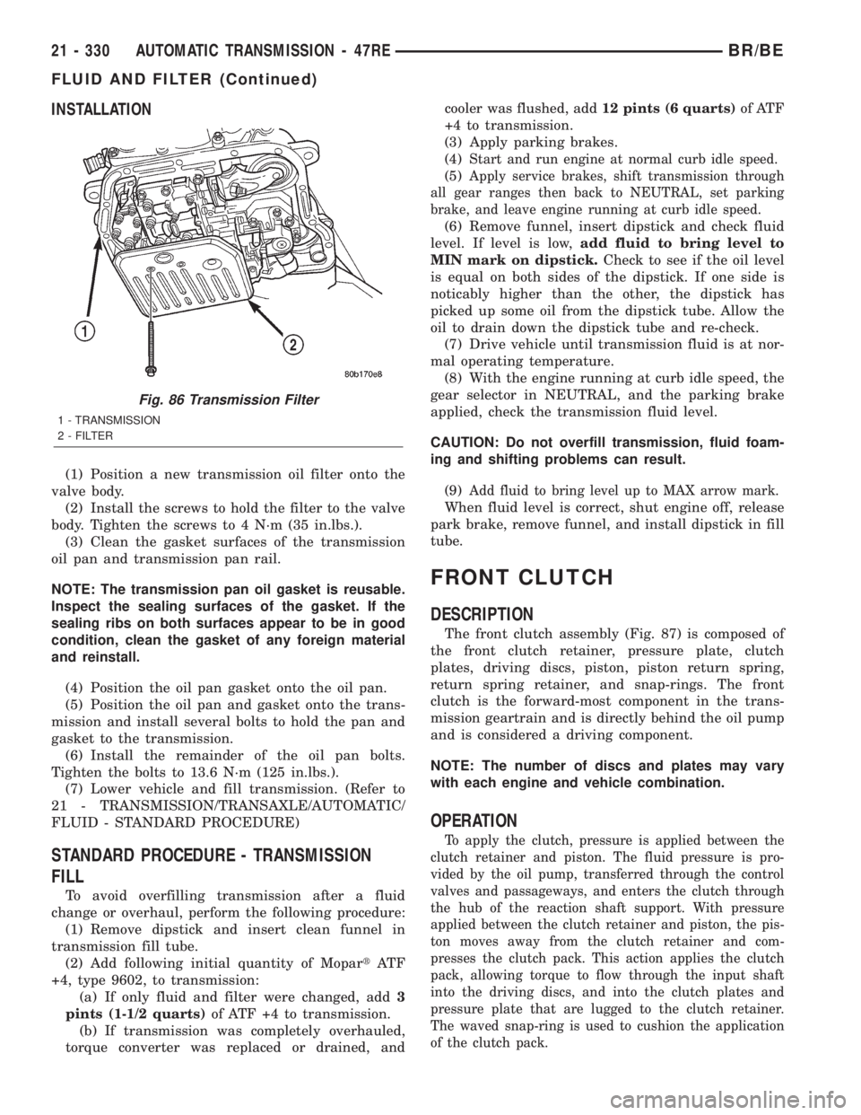
(1) Position a new transmission oil filter onto the
valve body.
(2) Install the screws to hold the filter to the valve
body. Tighten the screws to 4 N´m (35 in.lbs.).
(3) Clean the gasket surfaces of the transmission
oil pan and transmission pan rail.
NOTE: The transmission pan oil gasket is reusable.
Inspect the sealing surfaces of the gasket. If the
sealing ribs on both surfaces appear to be in good
condition, clean the gasket of any foreign material
and reinstall.
(4) Position the oil pan gasket onto the oil pan.
(5) Position the oil pan and gasket onto the trans-
mission and install several bolts to hold the pan and
gasket to the transmission.
(6) Install the remainder of the oil pan bolts.
Tighten the bolts to 13.6 N´m (125 in.lbs.).
(7) Lower vehicle and fill transmission. (Refer to
21 - TRANSMISSION/TRANSAXLE/AUTOMATIC/
FLUID - STANDARD PROCEDURE)
STANDARD PROCEDURE - TRANSMISSION
FILL
To avoid overfilling transmission after a fluid
change or overhaul, perform the following procedure:
(1) Remove dipstick and insert clean funnel in
transmission fill tube.
(2) Add following initial quantity of MopartAT F
+4, type 9602, to transmission:
(a) If only fluid and filter were changed, add3
pints (1-1/2 quarts)of ATF +4 to transmission.
(b) If transmission was completely overhauled,
torque converter was replaced or drained, andcooler was flushed, add12 pints (6 quarts)of ATF
+4 to transmission.
(3) Apply parking brakes.
(4)
Start and run engine at normal curb idle speed.
(5)Apply service brakes, shift transmission through
all gear ranges then back to NEUTRAL, set parking
brake, and leave engine running at curb idle speed.
(6) Remove funnel, insert dipstick and check fluid
level. If level is low,add fluid to bring level to
MIN mark on dipstick.Check to see if the oil level
is equal on both sides of the dipstick. If one side is
noticably higher than the other, the dipstick has
picked up some oil from the dipstick tube. Allow the
oil to drain down the dipstick tube and re-check.
(7) Drive vehicle until transmission fluid is at nor-
mal operating temperature.
(8) With the engine running at curb idle speed, the
gear selector in NEUTRAL, and the parking brake
applied, check the transmission fluid level.
CAUTION: Do not overfill transmission, fluid foam-
ing and shifting problems can result.
(9)
Add fluid to bring level up to MAX arrow mark.
When fluid level is correct, shut engine off, release
park brake, remove funnel, and install dipstick in fill
tube.
FRONT CLUTCH
DESCRIPTION
The front clutch assembly (Fig. 87) is composed of
the front clutch retainer, pressure plate, clutch
plates, driving discs, piston, piston return spring,
return spring retainer, and snap-rings. The front
clutch is the forward-most component in the trans-
mission geartrain and is directly behind the oil pump
and is considered a driving component.
NOTE: The number of discs and plates may vary
with each engine and vehicle combination.
OPERATION
To apply the clutch, pressure is applied between the
clutch retainer and piston. The fluid pressure is pro-
vided by the oil pump, transferred through the control
valves and passageways, and enters the clutch through
the hub of the reaction shaft support. With pressure
applied between the clutch retainer and piston, the pis-
ton moves away from the clutch retainer and com-
presses the clutch pack. This action applies the clutch
pack, allowing torque to flow through the input shaft
into the driving discs, and into the clutch plates and
pressure plate that are lugged to the clutch retainer.
The waved snap-ring is used to cushion the application
of the clutch pack.
Fig. 86 Transmission Filter
1 - TRANSMISSION
2 - FILTER
21 - 330 AUTOMATIC TRANSMISSION - 47REBR/BE
FLUID AND FILTER (Continued)
Page 1784 of 2255

When pressure is released from the piston, the
spring returns the piston to its fully released position
and disengages the clutch. The release spring also
helps to cushion the application of the clutch assem-
bly. When the clutch is in the process of being
released by the release spring, fluid flows through a
vent and one-way ball-check-valve located in the
clutch retainer. The check-valve is needed to elimi-
nate the possibility of plate drag caused by centrifu-
gal force acting on the residual fluid trapped in the
clutch piston retainer.
DISASSEMBLY
(1) Remove the waved snap-ring, reaction plate,
clutch plates, and clutch discs.
(2) Compress clutch piston retainer and piston
springs with Compressor Tool C-3863-A (Fig. 88).
(3) Remove retainer snap-ring and remove com-
pressor tool.
(4) Remove clutch piston springs (Fig. 89). Note
position of piston springs for assembly reference.
(5) Remove clutch piston from retainer with a
twisting motion.
(6) Remove and discard clutch piston inner and
outer seals.
Fig. 87 Front Clutch Components
1 - INNER PISTON SEAL 7 - CLUTCH DISCS
2 - CLUTCH PISTON 8 - RETAINER SNAP-RING
3 - CLUTCH PISTON SPRING RETAINER 9 - CLUTCH PISTON SPRINGS (9)
4 - CLUTCH PLATES 10 - OUTER PISTON SEAL
5 - CLUTCH PACK SNAP-RING (WAVED) 11 - FRONT CLUTCH RETAINER
6 - REACTION PLATE
Fig. 88 Removing Front Clutch Spring Retainer
Snap-Ring
1 - SPECIAL TOOL C-3863-A
2 - SNAP-RING
BR/BEAUTOMATIC TRANSMISSION - 47RE 21 - 331
FRONT CLUTCH (Continued)
Page 1786 of 2255

ASSEMBLY
NOTE: The 47RE transmission uses four plates and
discs for the front clutch.
(1) Mount Bushing Installer SP-5511 on tool han-
dle (Fig. 91).
(2) Slide new bushing onto installer tool and start
bushing into retainer.
(3) Tap new bushing into place until installer tool
bottoms against clutch retainer.
(4) Remove installer tools and clean retainer thor-
oughly.
(5) Soak clutch discs in transmission fluid.
(6) Install new inner piston seal onto the outer
diameter of the clutch retainer inner hub.
(7) Install new outer seal onto the clutch piston.
Be sure seal lips of both seals face the interior of the
retainer.
(8) Lubricate new inner and outer piston seals
with Ru-GlydeŸ, or MopartDoor Ease.
(9) Install clutch piston in retainer. Use twisting
motion to seat piston in bottom of retainer. A thin
strip of plastic (about 0.015 - 0.020 in. thick), can be
used to guide seals into place if necessary.CAUTION: Never push the clutch piston straight in.
This will fold the seals over causing leakage and
clutch slip. In addition, never use any type of metal
tool to help ease the piston seals into place. Metal
tools will cut, shave, or score the seals.
(10) Install and position nine clutch piston springs
(Fig. 92).
Fig. 90 Front Clutch Retainer Bushing Replacement
Tools
1 - SPECIAL TOOL C-4171
2 - SPECIAL TOOL SP-3629
3 - SPECIAL TOOL SP-5511
4 - SPECIAL TOOL C-4171
5 - FRONT CLUTCH RETAINER
Fig. 91 Front Clutch Retainer Bushing Replacement
Tools
1 - SPECIAL TOOL C-4171
2 - SPECIAL TOOL SP-3629
3 - SPECIAL TOOL SP-5511
4 - SPECIAL TOOL C-4171
5 - FRONT CLUTCH RETAINER
Fig. 92 Front Clutch Spring Position
1 - 9 SPRING CLUTCH
BR/BEAUTOMATIC TRANSMISSION - 47RE 21 - 333
FRONT CLUTCH (Continued)
Page 1789 of 2255
OIL PUMP
DESCRIPTION
The oil pump (Fig. 99) is located in the pump hous-
ing inside the bell housing of the transmission case.
The oil pump consists of an inner and outer gear, a
housing, and a reaction shaft support.
OPERATION
As the torque converter rotates, the converter hub
rotates the inner and outer gears. As the gears
rotate, the clearance between the gear teeth
increases in the crescent area, and creates a suction
at the inlet side of the pump. This suction draws
fluid through the pump inlet from the oil pan. As the
clearance between the gear teeth in the crescent area
decreases, it forces pressurized fluid into the pump
outlet and to the valve body.
STANDARD PROCEDURE - OIL PUMP VOLUME
CHECK
Measuring the oil pump output volume will deter-
mine if sufficient oil flow to the transmission oil
cooler exists, and whether or not an internal trans-
mission failure is present.
Verify that the transmission fluid is at the proper
level. Refer to the Fluid Level Check procedure in
this section. If necessary, fill the transmission to the
proper level with MopartATF +4, type 9602, Auto-
matic Transmission Fluid.
(1) Disconnect theTo coolerline at the cooler
inlet and place a collecting container under the dis-
connected line.
CAUTION: With the fluid set at the proper level,
fluid collection should not exceed (1) quart or inter-
nal damage to the transmission may occur.
(2) Run the engineat curb idle speed, with the
shift selector in neutral.
(3) If one quart of transmission fluid is collected in
the container in 20 seconds or less, oil pump flow vol-
ume is within acceptable limits. If fluid flow is inter-
mittent, or it takes more than 20 seconds to collect
one quart of fluid, refer to the Hydraulic Pressure
tests in this section for further diagnosis.
(4) Re-connect theTo coolerline to the transmis-
sion cooler inlet.
(5) Refill the transmission to proper level.
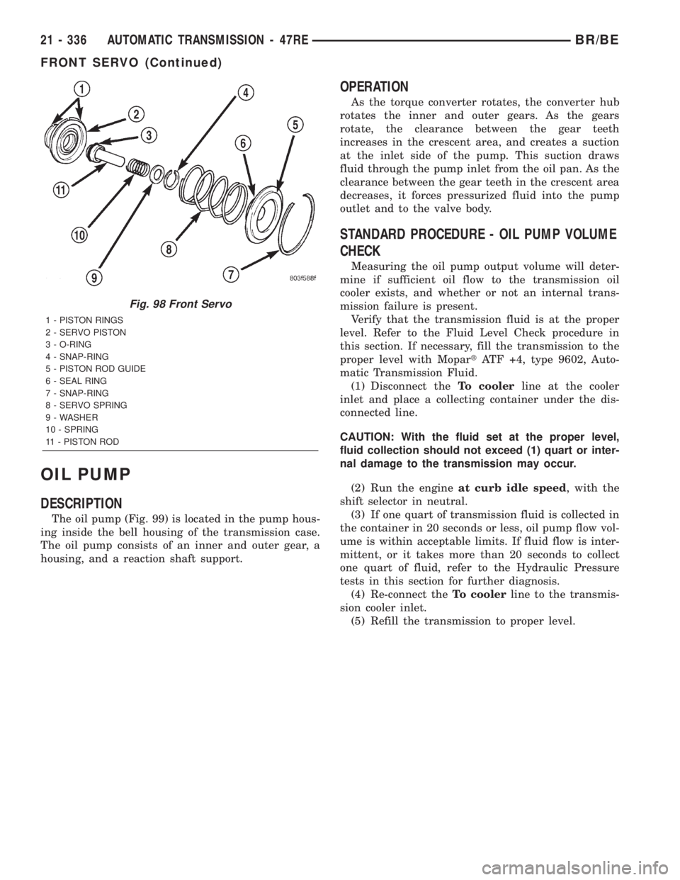
Fig. 98 Front Servo
1 - PISTON RINGS
2 - SERVO PISTON
3 - O-RING
4 - SNAP-RING
5 - PISTON ROD GUIDE
6 - SEAL RING
7 - SNAP-RING
8 - SERVO SPRING
9 - WASHER
10 - SPRING
11 - PISTON ROD
21 - 336 AUTOMATIC TRANSMISSION - 47REBR/BE
FRONT SERVO (Continued)
Page 1794 of 2255
REACTION SHAFT SUPPORT BUSHING
(1) Place reaction shaft support upright on a clean,
smooth surface.
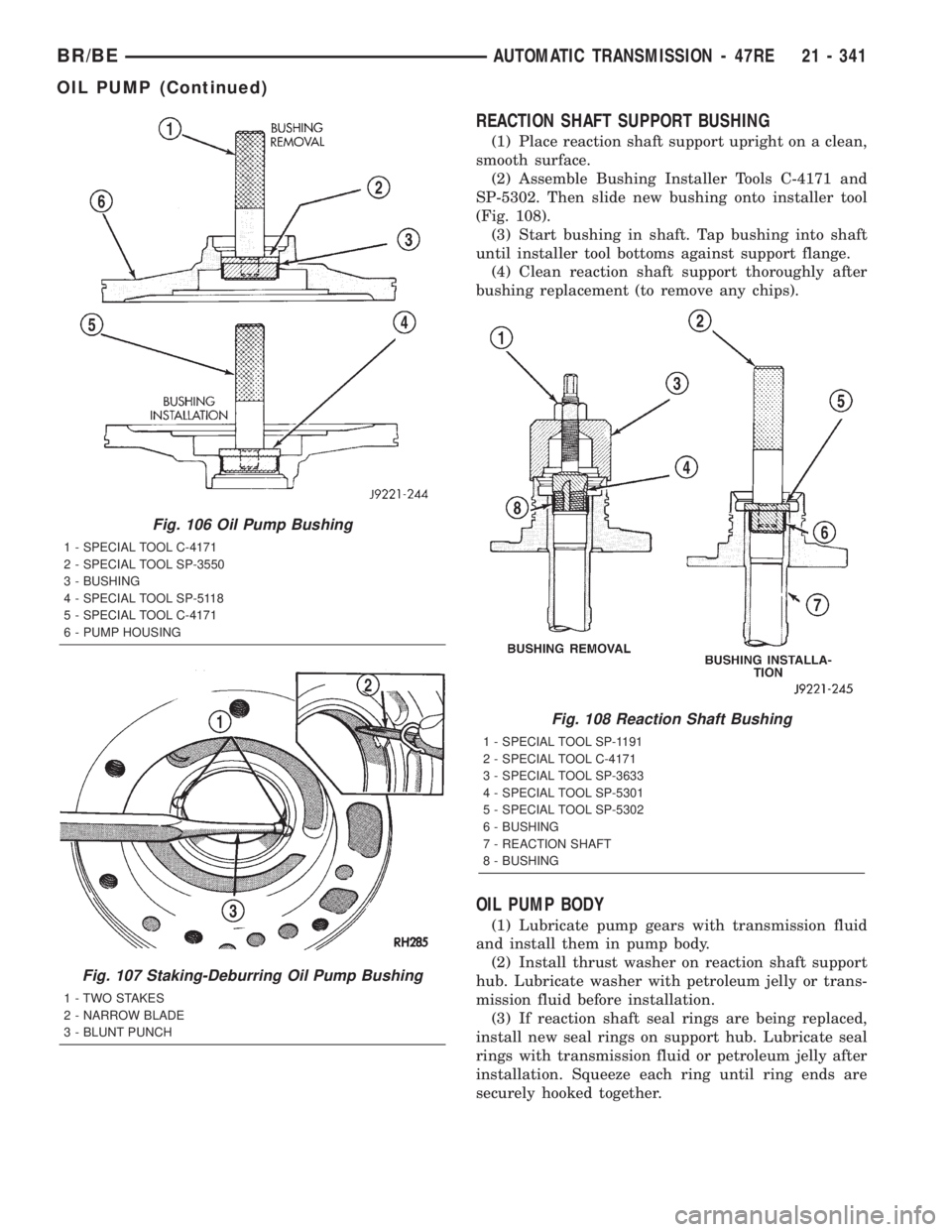
(2) Assemble Bushing Installer Tools C-4171 and
SP-5302. Then slide new bushing onto installer tool
(Fig. 108).
(3) Start bushing in shaft. Tap bushing into shaft
until installer tool bottoms against support flange.
(4) Clean reaction shaft support thoroughly after
bushing replacement (to remove any chips).
OIL PUMP BODY
(1) Lubricate pump gears with transmission fluid
and install them in pump body.
(2) Install thrust washer on reaction shaft support
hub. Lubricate washer with petroleum jelly or trans-
mission fluid before installation.
(3) If reaction shaft seal rings are being replaced,
install new seal rings on support hub. Lubricate seal
rings with transmission fluid or petroleum jelly after
installation. Squeeze each ring until ring ends are
securely hooked together.
Fig. 106 Oil Pump Bushing
1 - SPECIAL TOOL C-4171
2 - SPECIAL TOOL SP-3550
3 - BUSHING
4 - SPECIAL TOOL SP-5118
5 - SPECIAL TOOL C-4171
6 - PUMP HOUSING
Fig. 107 Staking-Deburring Oil Pump Bushing
1 - TWO STAKES
2 - NARROW BLADE
3 - BLUNT PUNCH
Fig. 108 Reaction Shaft Bushing
1 - SPECIAL TOOL SP-1191
2 - SPECIAL TOOL C-4171
3 - SPECIAL TOOL SP-3633
4 - SPECIAL TOOL SP-5301
5 - SPECIAL TOOL SP-5302
6 - BUSHING
7 - REACTION SHAFT
8 - BUSHING
BR/BEAUTOMATIC TRANSMISSION - 47RE 21 - 341
OIL PUMP (Continued)
Page 1796 of 2255
OUTPUT SHAFT REAR
BEARING
REMOVAL
(1) Remove overdrive unit from the vehicle. (Refer
to 21 - TRANSMISSION/TRANSAXLE/AUTOMATIC/
OVERDRIVE - REMOVAL)
(2) Remove overdrive geartrain from housing.
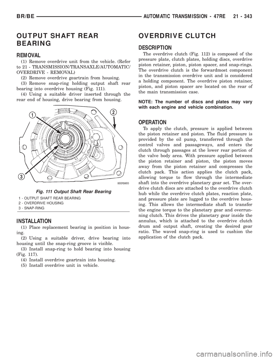
(3) Remove snap-ring holding output shaft rear
bearing into overdrive housing (Fig. 111).
(4) Using a suitable driver inserted through the
rear end of housing, drive bearing from housing.
INSTALLATION
(1) Place replacement bearing in position in hous-
ing.
(2) Using a suitable driver, drive bearing into
housing until the snap-ring groove is visible.
(3) Install snap-ring to hold bearing into housing
(Fig. 117).
(4) Install overdrive geartrain into housing.
(5) Install overdrive unit in vehicle.
OVERDRIVE CLUTCH
DESCRIPTION
The overdrive clutch (Fig. 112) is composed of the
pressure plate, clutch plates, holding discs, overdrive
piston retainer, piston, piston spacer, and snap-rings.
The overdrive clutch is the forwardmost component
in the transmission overdrive unit and is considered
a holding component. The overdrive piston retainer,
piston, and piston spacer are located on the rear of
the main transmission case.
NOTE: The number of discs and plates may vary
with each engine and vehicle combination.
OPERATION
To apply the clutch, pressure is applied between
the piston retainer and piston. The fluid pressure is
provided by the oil pump, transferred through the
control valves and passageways, and enters the
clutch through passages at the lower rear portion of
the valve body area. With pressure applied between
the piston retainer and piston, the piston moves
away from the piston retainer and compresses the
clutch pack. This action applies the clutch pack,
allowing torque to flow through the intermediate
shaft into the overdrive planetary gear set. The over-
drive clutch discs are attached to the overdrive clutch
hub while the overdrive clutch plates, reaction plate,
and pressure plate are lugged to the overdrive hous-
ing. This allows the intermediate shaft to transfer
the engine torque to the planetary gear and overrun-
ning clutch. This drives the planetary gear inside the
annulus, which is attached to the overdrive clutch
drum and output shaft, creating the desired gear
ratio. The waved snap-ring is used to cushion the
application of the clutch pack.
Fig. 111 Output Shaft Rear Bearing
1 - OUTPUT SHAFT REAR BEARING
2 - OVERDRIVE HOUSING
3 - SNAP-RING
BR/BEAUTOMATIC TRANSMISSION - 47RE 21 - 343
Page 1798 of 2255
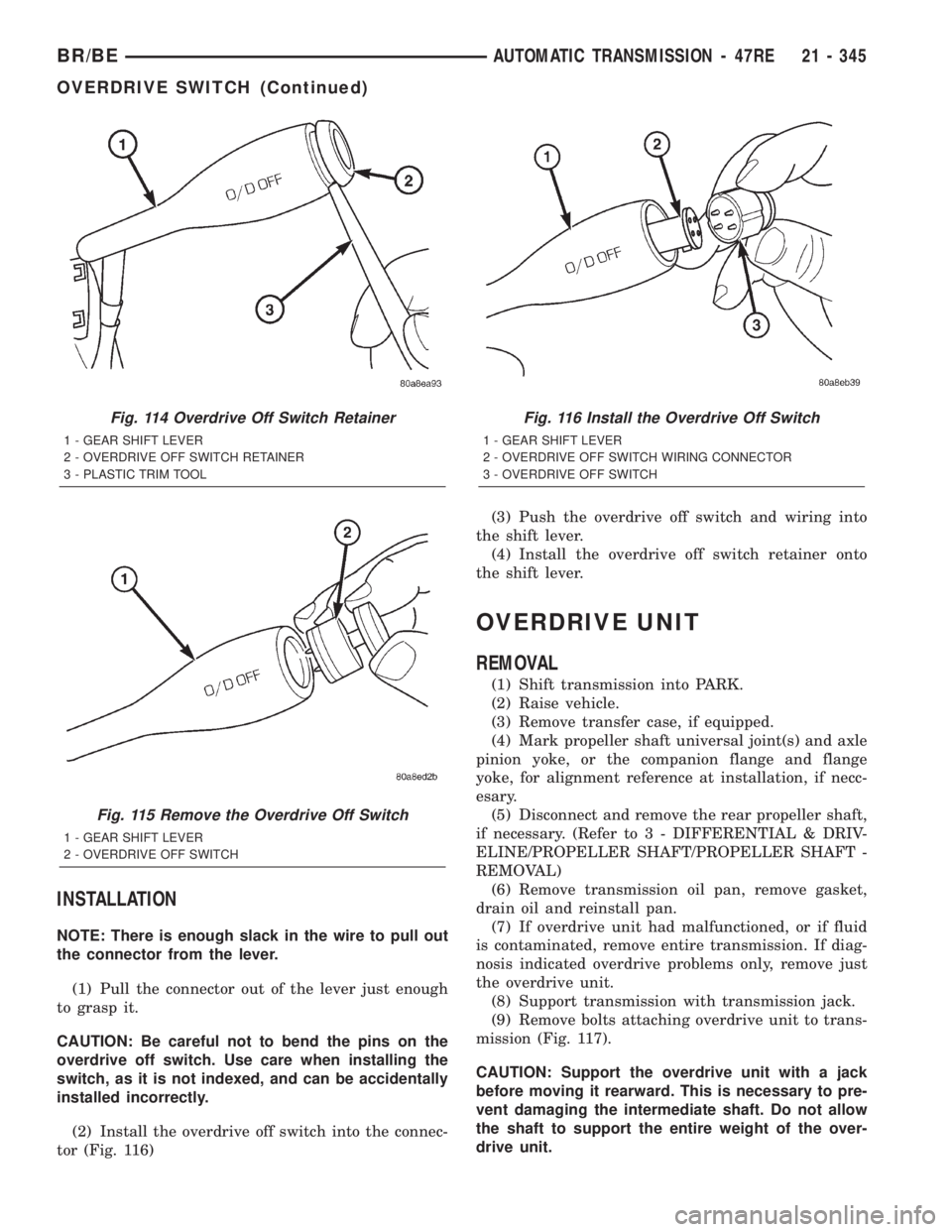
INSTALLATION
NOTE: There is enough slack in the wire to pull out
the connector from the lever.
(1) Pull the connector out of the lever just enough
to grasp it.
CAUTION: Be careful not to bend the pins on the
overdrive off switch. Use care when installing the
switch, as it is not indexed, and can be accidentally
installed incorrectly.
(2) Install the overdrive off switch into the connec-
tor (Fig. 116)(3) Push the overdrive off switch and wiring into
the shift lever.
(4) Install the overdrive off switch retainer onto
the shift lever.
OVERDRIVE UNIT
REMOVAL
(1) Shift transmission into PARK.
(2) Raise vehicle.
(3) Remove transfer case, if equipped.
(4) Mark propeller shaft universal joint(s) and axle
pinion yoke, or the companion flange and flange
yoke, for alignment reference at installation, if necc-
esary.
(5) Disconnect and remove the rear propeller shaft,
if necessary. (Refer to 3 - DIFFERENTIAL & DRIV-
ELINE/PROPELLER SHAFT/PROPELLER SHAFT -
REMOVAL)
(6) Remove transmission oil pan, remove gasket,
drain oil and reinstall pan.
(7) If overdrive unit had malfunctioned, or if fluid
is contaminated, remove entire transmission. If diag-
nosis indicated overdrive problems only, remove just
the overdrive unit.
(8) Support transmission with transmission jack.
(9) Remove bolts attaching overdrive unit to trans-
mission (Fig. 117).
CAUTION: Support the overdrive unit with a jack
before moving it rearward. This is necessary to pre-
vent damaging the intermediate shaft. Do not allow
the shaft to support the entire weight of the over-
drive unit.
Fig. 114 Overdrive Off Switch Retainer
1 - GEAR SHIFT LEVER
2 - OVERDRIVE OFF SWITCH RETAINER
3 - PLASTIC TRIM TOOL
Fig. 115 Remove the Overdrive Off Switch
1 - GEAR SHIFT LEVER
2 - OVERDRIVE OFF SWITCH
Fig. 116 Install the Overdrive Off Switch
1 - GEAR SHIFT LEVER
2 - OVERDRIVE OFF SWITCH WIRING CONNECTOR
3 - OVERDRIVE OFF SWITCH
BR/BEAUTOMATIC TRANSMISSION - 47RE 21 - 345
OVERDRIVE SWITCH (Continued)
Page 1799 of 2255

(10) Carefully work overdrive unit off intermediate
shaft. Do not tilt unit during removal. Keep it as
level as possible.
(11) If overdrive unit does not require service,
immediately insert Alignment Tool 6227-2 in splines
of planetary gear and overrunning clutch to prevent
splines from rotating out of alignment. If misalign-
ment occurs, overdrive unit will have to be disassem-
bled in order to realign splines.
(12) Remove and retain overdrive piston thrust
bearing. Bearing may remain on piston or in clutch
hub during removal.
(13) Position drain pan on workbench.
(14) Place overdrive unit over drain pan. Tilt unit
to drain residual fluid from case.
(15) Examine fluid for clutch material or metal
fragments. If fluid contains these items, overhaul will
be necessary.
(16) If overdrive unit does not require any service,
leave alignment tool in position. Tool will prevent
accidental misalignment of planetary gear and over-
running clutch splines.
DISASSEMBLY
(1) Remove transmission speed sensor and o-ring
seal from overdrive case (Fig. 118).
(2) Remove overdrive piston thrust bearing (Fig.
119).
Fig. 117 Overdrive Unit Bolts
1 - OVERDRIVE UNIT
2 - ATTACHING BOLTS (7)
Fig. 118 Transmission Speed Sensor
1 - SOCKET AND WRENCH
2 - SPEED SENSOR
3 - O-RING
Fig. 119 Overdrive Piston Thrust Bearing Removal/
Installation
1 - THRUST BEARING
2 - OVERDRIVE PISTON
3 - THRUST PLATE
21 - 346 AUTOMATIC TRANSMISSION - 47REBR/BE
OVERDRIVE UNIT (Continued)
Page 1806 of 2255
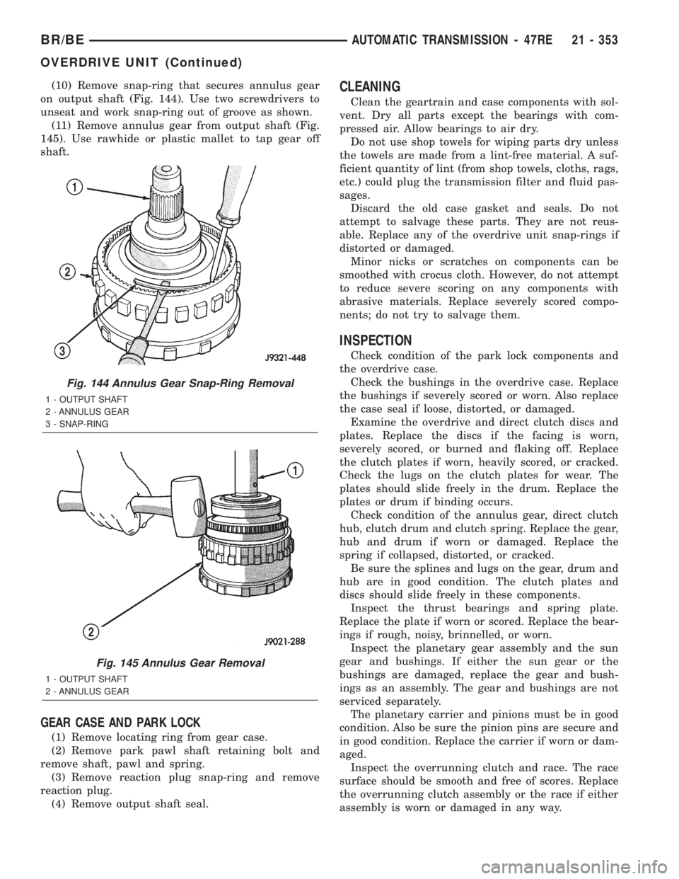
(10) Remove snap-ring that secures annulus gear
on output shaft (Fig. 144). Use two screwdrivers to
unseat and work snap-ring out of groove as shown.
(11) Remove annulus gear from output shaft (Fig.
145). Use rawhide or plastic mallet to tap gear off
shaft.
GEAR CASE AND PARK LOCK
(1) Remove locating ring from gear case.
(2) Remove park pawl shaft retaining bolt and
remove shaft, pawl and spring.
(3) Remove reaction plug snap-ring and remove
reaction plug.
(4) Remove output shaft seal.
CLEANING
Clean the geartrain and case components with sol-
vent. Dry all parts except the bearings with com-
pressed air. Allow bearings to air dry.
Do not use shop towels for wiping parts dry unless
the towels are made from a lint-free material. A suf-
ficient quantity of lint (from shop towels, cloths, rags,
etc.) could plug the transmission filter and fluid pas-
sages.
Discard the old case gasket and seals. Do not
attempt to salvage these parts. They are not reus-
able. Replace any of the overdrive unit snap-rings if
distorted or damaged.
Minor nicks or scratches on components can be
smoothed with crocus cloth. However, do not attempt
to reduce severe scoring on any components with
abrasive materials. Replace severely scored compo-
nents; do not try to salvage them.
INSPECTION
Check condition of the park lock components and
the overdrive case.
Check the bushings in the overdrive case. Replace
the bushings if severely scored or worn. Also replace
the case seal if loose, distorted, or damaged.
Examine the overdrive and direct clutch discs and
plates. Replace the discs if the facing is worn,
severely scored, or burned and flaking off. Replace
the clutch plates if worn, heavily scored, or cracked.
Check the lugs on the clutch plates for wear. The
plates should slide freely in the drum. Replace the
plates or drum if binding occurs.
Check condition of the annulus gear, direct clutch
hub, clutch drum and clutch spring. Replace the gear,
hub and drum if worn or damaged. Replace the
spring if collapsed, distorted, or cracked.
Be sure the splines and lugs on the gear, drum and
hub are in good condition. The clutch plates and
discs should slide freely in these components.
Inspect the thrust bearings and spring plate.
Replace the plate if worn or scored. Replace the bear-
ings if rough, noisy, brinnelled, or worn.
Inspect the planetary gear assembly and the sun
gear and bushings. If either the sun gear or the
bushings are damaged, replace the gear and bush-
ings as an assembly. The gear and bushings are not
serviced separately.
The planetary carrier and pinions must be in good
condition. Also be sure the pinion pins are secure and
in good condition. Replace the carrier if worn or dam-
aged.
Inspect the overrunning clutch and race. The race
surface should be smooth and free of scores. Replace
the overrunning clutch assembly or the race if either
assembly is worn or damaged in any way.
Fig. 144 Annulus Gear Snap-Ring Removal
1 - OUTPUT SHAFT
2 - ANNULUS GEAR
3 - SNAP-RING
Fig. 145 Annulus Gear Removal
1 - OUTPUT SHAFT
2 - ANNULUS GEAR
BR/BEAUTOMATIC TRANSMISSION - 47RE 21 - 353
OVERDRIVE UNIT (Continued)
Page 1807 of 2255

Replace the shaft pilot bushing and inner bushing
if damaged. Replace either shaft bearing if rough or
noisy. Replace the bearing snap-rings if distorted or
cracked.
Check the machined surfaces on the output shaft.
These surfaces should clean and smooth. Very minor
nicks or scratches can be smoothed with crocus cloth.
Replace the shaft if worn, scored or damaged in any
way.
Inspect the output shaft bushings. The small bush-
ing is the intermediate shaft pilot bushing. The large
bushing is the overrunning clutch hub bushing.
Replace either bushing if scored, pitted, cracked, or
worn.
ASSEMBLY
GEARTRAIN AND DIRECT CLUTCH
(1) Soak direct clutch and overdrive clutch discs in
MopartATF +4, type 9602, transmission fluid. Allow
discs to soak for 10-20 minutes.
(2) Install new pilot bushing and clutch hub bush-
ing in output shaft if necessary (Fig. 146). Lubricate
bushings with petroleum jelly, or transmission fluid.
(3) Install annulus gear on output shaft, if
removed. Then install annulus gear retaining snap-
ring (Fig. 147).(4) Align and install clutch drum on annulus gear
(Fig. 148). Be sure drum is engaged in annulus gear
lugs.
(5) Install clutch drum outer retaining ring (Fig.
148).
Fig. 146 Output Shaft Pilot Bushing
1 - OUTPUT SHAFT HUB
2 - OVERRUNNING CLUTCH HUB BUSHING
3 - INTERMEDIATE SHAFT PILOT BUSHING
Fig. 147 Annulus Gear Installation
1 - SNAP-RING
2 - OUTPUT SHAFT FRONT BEARING
3 - ANNULUS GEAR
Fig. 148 Clutch Drum And Outer Retaining Ring
Installation
1 - ANNULUS GEAR
2 - OUTER SNAP-RING
3 - CLUTCH DRUM
21 - 354 AUTOMATIC TRANSMISSION - 47REBR/BE
OVERDRIVE UNIT (Continued)