DODGE RAM 2002 Service Repair Manual
Manufacturer: DODGE, Model Year: 2002, Model line: RAM, Model: DODGE RAM 2002Pages: 2255, PDF Size: 62.07 MB
Page 1621 of 2255
CLEANING
Clean pump and support components with solvent
and dry them with compressed air.
INSPECTION
Check condition of the seal rings and thrust
washer on the reaction shaft support. The seal rings
do not need to be replaced unless cracked, broken, or
severely worn.
Inspect the pump and support components. Replace
the pump or support if the seal ring grooves or
machined surfaces are worn, scored, pitted, or dam-
aged. Replace the pump gears if pitted, worn
chipped, or damaged.
Inspect the pump bushing. Then check the reaction
shaft support bushing. Replace either bushing only if
heavily worn, scored or damaged. It is not necessary
to replace the bushings unless they are actually dam-
aged.Clearance between outer gear and reaction shaft
housing should be 0.010 to 0.063 mm (0.0004 to
0.0025 in.). Clearance between inner gear and reac-
tion shaft housing should be 0.010 to 0.063 mm
(0.0004 to 0.0025 in.). Both clearances can be mea-
sured at the same time by installing the gears in the
pump body and measure pump component clearances
as follows:
(1) Position an appropriate piece of PlastigageŸ
across both gears.
(2) Align the plastigage to a flat area on the reac-
tion shaft housing.
(3) Install the reaction shaft to the pump housing.
(4) Separate the reaction shaft housing from the
pump housing and measure the PlastigageŸ follow-
ing the instructions supplied with it.
Clearance between inner gear tooth and outer gear
should be 0.08 to 0.19 mm (0.0035 to 0.0075 in.).
Measure clearance with an appropriate feeler gauge
(Fig. 111).
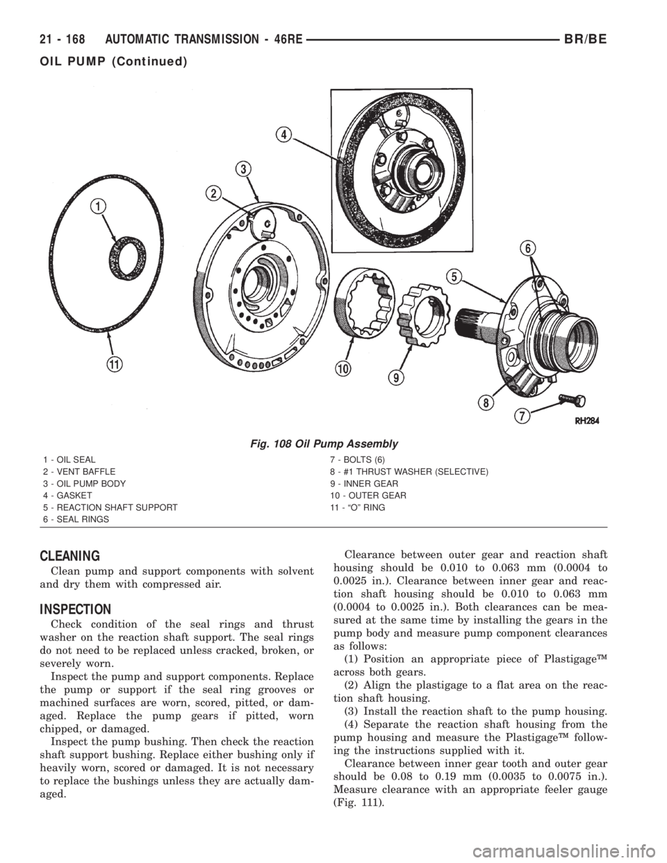
Fig. 108 Oil Pump Assembly
1 - OIL SEAL 7 - BOLTS (6)
2 - VENT BAFFLE 8 - #1 THRUST WASHER (SELECTIVE)
3 - OIL PUMP BODY 9 - INNER GEAR
4 - GASKET 10 - OUTER GEAR
5 - REACTION SHAFT SUPPORT 11 - ªOº RING
6 - SEAL RINGS
21 - 168 AUTOMATIC TRANSMISSION - 46REBR/BE
OIL PUMP (Continued)
Page 1622 of 2255
Clearance between outer gear and pump housing
should be 0.10 to 0.19 mm (0.004 to 0.0075 in.). Mea-
sure clearance with an appropriate feeler gauge.
ASSEMBLY
OIL PUMP BUSHING
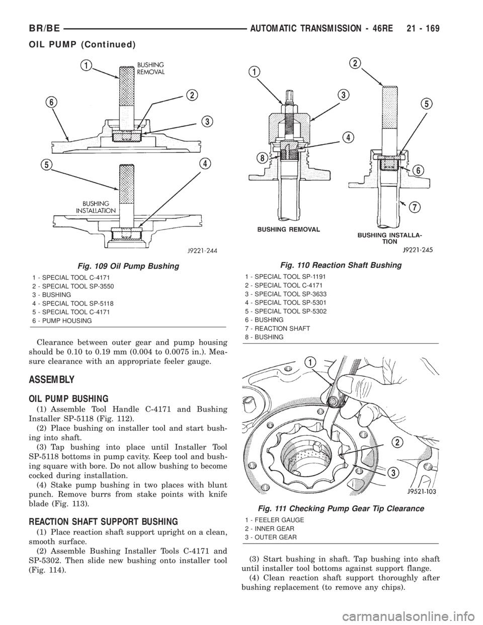
(1) Assemble Tool Handle C-4171 and Bushing
Installer SP-5118 (Fig. 112).
(2) Place bushing on installer tool and start bush-
ing into shaft.
(3) Tap bushing into place until Installer Tool
SP-5118 bottoms in pump cavity. Keep tool and bush-
ing square with bore. Do not allow bushing to become
cocked during installation.
(4) Stake pump bushing in two places with blunt
punch. Remove burrs from stake points with knife
blade (Fig. 113).
REACTION SHAFT SUPPORT BUSHING
(1) Place reaction shaft support upright on a clean,
smooth surface.
(2) Assemble Bushing Installer Tools C-4171 and
SP-5302. Then slide new bushing onto installer tool
(Fig. 114).(3) Start bushing in shaft. Tap bushing into shaft
until installer tool bottoms against support flange.
(4) Clean reaction shaft support thoroughly after
bushing replacement (to remove any chips).
Fig. 109 Oil Pump Bushing
1 - SPECIAL TOOL C-4171
2 - SPECIAL TOOL SP-3550
3 - BUSHING
4 - SPECIAL TOOL SP-5118
5 - SPECIAL TOOL C-4171
6 - PUMP HOUSING
Fig. 110 Reaction Shaft Bushing
1 - SPECIAL TOOL SP-1191
2 - SPECIAL TOOL C-4171
3 - SPECIAL TOOL SP-3633
4 - SPECIAL TOOL SP-5301
5 - SPECIAL TOOL SP-5302
6 - BUSHING
7 - REACTION SHAFT
8 - BUSHING
Fig. 111 Checking Pump Gear Tip Clearance
1 - FEELER GAUGE
2 - INNER GEAR
3 - OUTER GEAR
BR/BEAUTOMATIC TRANSMISSION - 46RE 21 - 169
OIL PUMP (Continued)
Page 1623 of 2255
OIL PUMP BODY
(1) Lubricate pump gears with transmission fluid
and install them in pump body.(2) Install thrust washer on reaction shaft support
hub. Lubricate washer with petroleum jelly or trans-
mission fluid before installation.
(3) If reaction shaft seal rings are being replaced,
install new seal rings on support hub. Lubricate seal
rings with transmission fluid or petroleum jelly after
installation. Squeeze each ring until ring ends are
securely hooked together.
CAUTION: The reaction shaft support seal rings will
break if overspread, or twisted. If new rings are
being installed, spread them only enough for instal-
lation. Also be very sure the ring ends are securely
hooked together after installation. Otherwise, the
rings will either prevent pump installation, or break
during installation.
(4) Align and install reaction shaft support on
pump body.
(5) Install bolts attaching reaction shaft support to
pump. Tighten bolts to 20 N´m (175 in. lbs.) torque.
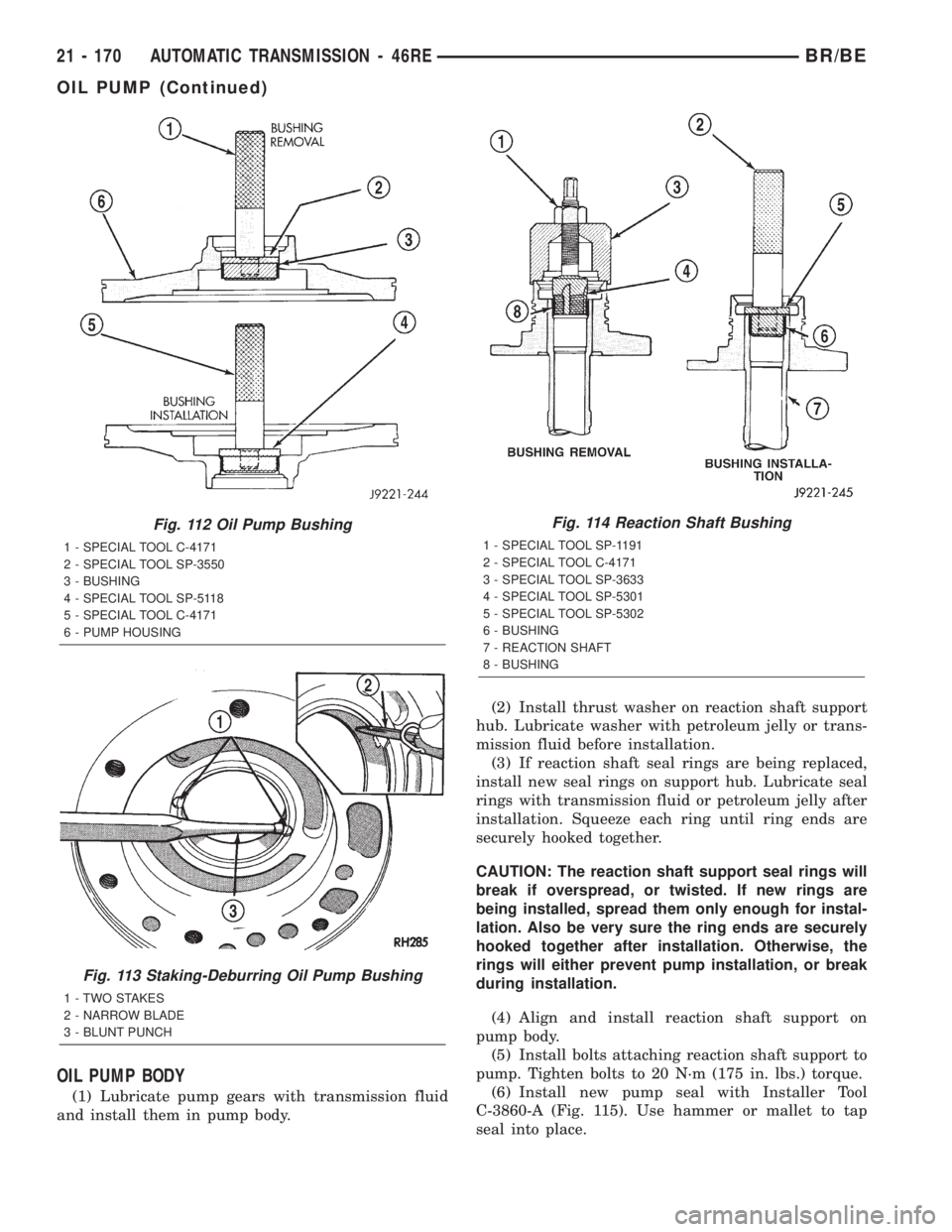
(6) Install new pump seal with Installer Tool
C-3860-A (Fig. 115). Use hammer or mallet to tap
seal into place.
Fig. 112 Oil Pump Bushing
1 - SPECIAL TOOL C-4171
2 - SPECIAL TOOL SP-3550
3 - BUSHING
4 - SPECIAL TOOL SP-5118
5 - SPECIAL TOOL C-4171
6 - PUMP HOUSING
Fig. 113 Staking-Deburring Oil Pump Bushing
1 - TWO STAKES
2 - NARROW BLADE
3 - BLUNT PUNCH
Fig. 114 Reaction Shaft Bushing
1 - SPECIAL TOOL SP-1191
2 - SPECIAL TOOL C-4171
3 - SPECIAL TOOL SP-3633
4 - SPECIAL TOOL SP-5301
5 - SPECIAL TOOL SP-5302
6 - BUSHING
7 - REACTION SHAFT
8 - BUSHING
21 - 170 AUTOMATIC TRANSMISSION - 46REBR/BE
OIL PUMP (Continued)
Page 1624 of 2255
(7) Install new o-ring on pump body. Lubricate oil
seal and o-ring with petroleum jelly.
(8) Cover pump assembly to prevent dust entry
and set aside for assembly installation.
OUTPUT SHAFT FRONT
BEARING
REMOVAL
(1) Remove overdrive unit from the vehicle.
(2) Remove overdrive geartrain from housing.
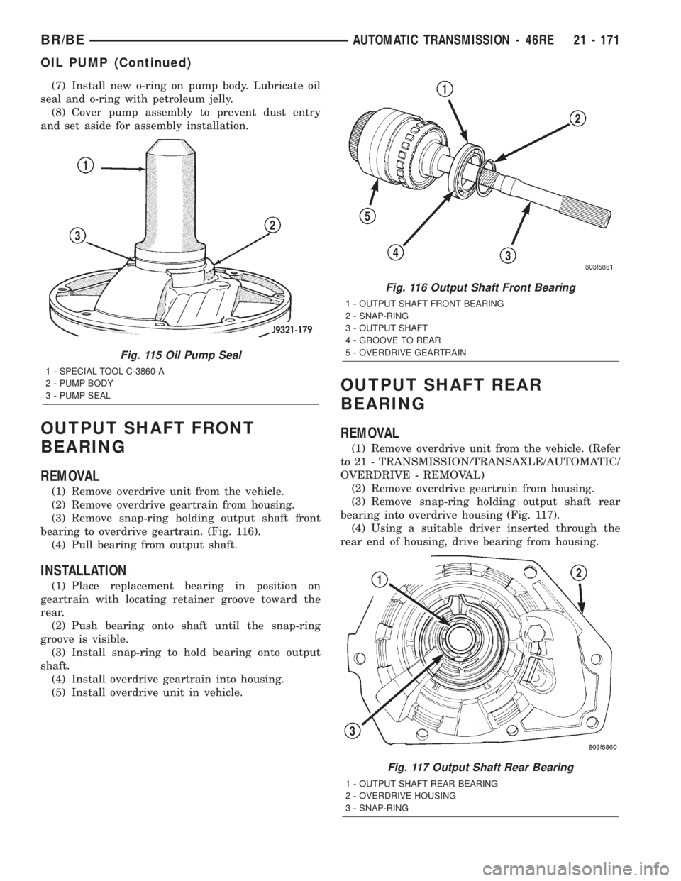
(3) Remove snap-ring holding output shaft front
bearing to overdrive geartrain. (Fig. 116).
(4) Pull bearing from output shaft.
INSTALLATION
(1) Place replacement bearing in position on
geartrain with locating retainer groove toward the
rear.
(2) Push bearing onto shaft until the snap-ring
groove is visible.
(3) Install snap-ring to hold bearing onto output
shaft.
(4) Install overdrive geartrain into housing.
(5) Install overdrive unit in vehicle.
OUTPUT SHAFT REAR
BEARING
REMOVAL
(1) Remove overdrive unit from the vehicle. (Refer
to 21 - TRANSMISSION/TRANSAXLE/AUTOMATIC/
OVERDRIVE - REMOVAL)
(2) Remove overdrive geartrain from housing.
(3) Remove snap-ring holding output shaft rear
bearing into overdrive housing (Fig. 117).
(4) Using a suitable driver inserted through the
rear end of housing, drive bearing from housing.
Fig. 115 Oil Pump Seal
1 - SPECIAL TOOL C-3860-A
2 - PUMP BODY
3 - PUMP SEAL
Fig. 116 Output Shaft Front Bearing
1 - OUTPUT SHAFT FRONT BEARING
2 - SNAP-RING
3 - OUTPUT SHAFT
4 - GROOVE TO REAR
5 - OVERDRIVE GEARTRAIN
Fig. 117 Output Shaft Rear Bearing
1 - OUTPUT SHAFT REAR BEARING
2 - OVERDRIVE HOUSING
3 - SNAP-RING
BR/BEAUTOMATIC TRANSMISSION - 46RE 21 - 171
OIL PUMP (Continued)
Page 1625 of 2255
INSTALLATION
(1) Place replacement bearing in position in hous-
ing.
(2) Using a suitable driver, drive bearing into
housing until the snap-ring groove is visible.
(3) Install snap-ring to hold bearing into housing
(Fig. 117).
(4) Install overdrive geartrain into housing.
(5) Install overdrive unit in vehicle.
OVERDRIVE CLUTCH
DESCRIPTION
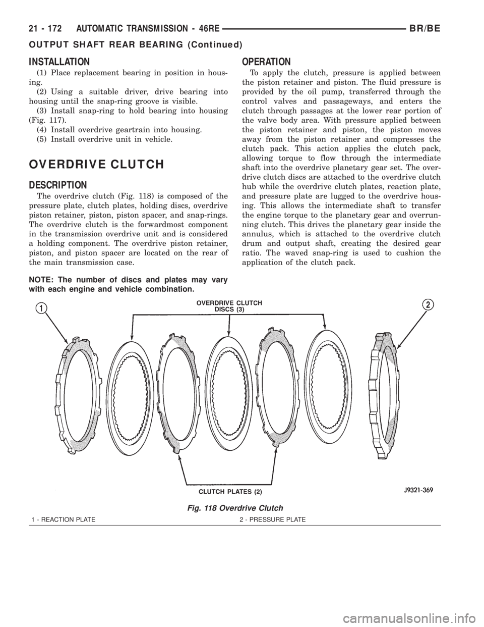
The overdrive clutch (Fig. 118) is composed of the
pressure plate, clutch plates, holding discs, overdrive
piston retainer, piston, piston spacer, and snap-rings.
The overdrive clutch is the forwardmost component
in the transmission overdrive unit and is considered
a holding component. The overdrive piston retainer,
piston, and piston spacer are located on the rear of
the main transmission case.
NOTE: The number of discs and plates may vary
with each engine and vehicle combination.
OPERATION
To apply the clutch, pressure is applied between
the piston retainer and piston. The fluid pressure is
provided by the oil pump, transferred through the
control valves and passageways, and enters the
clutch through passages at the lower rear portion of
the valve body area. With pressure applied between
the piston retainer and piston, the piston moves
away from the piston retainer and compresses the
clutch pack. This action applies the clutch pack,
allowing torque to flow through the intermediate
shaft into the overdrive planetary gear set. The over-
drive clutch discs are attached to the overdrive clutch
hub while the overdrive clutch plates, reaction plate,
and pressure plate are lugged to the overdrive hous-
ing. This allows the intermediate shaft to transfer
the engine torque to the planetary gear and overrun-
ning clutch. This drives the planetary gear inside the
annulus, which is attached to the overdrive clutch
drum and output shaft, creating the desired gear
ratio. The waved snap-ring is used to cushion the
application of the clutch pack.
Fig. 118 Overdrive Clutch
1 - REACTION PLATE 2 - PRESSURE PLATE
21 - 172 AUTOMATIC TRANSMISSION - 46REBR/BE
OUTPUT SHAFT REAR BEARING (Continued)
Page 1626 of 2255
OVERDRIVE UNIT
REMOVAL
(1) Shift transmission into PARK.
(2) Raise vehicle.
(3) Remove transfer case, if equipped.
(4) Mark propeller shaft universal joint(s) and axle
pinion yoke, or the companion flange and flange
yoke, for alignment reference at installation, if necc-
esary.
(5) Disconnect and remove the rear propeller shaft,
if necessary. (Refer to 3 - DIFFERENTIAL & DRIV-
ELINE/PROPELLER SHAFT/PROPELLER SHAFT -
REMOVAL)
(6) Remove transmission oil pan, remove gasket,
drain oil and reinstall pan.
(7) If overdrive unit had malfunctioned, or if fluid
is contaminated, remove entire transmission. If diag-
nosis indicated overdrive problems only, remove just
the overdrive unit.
(8) Support transmission with transmission jack.
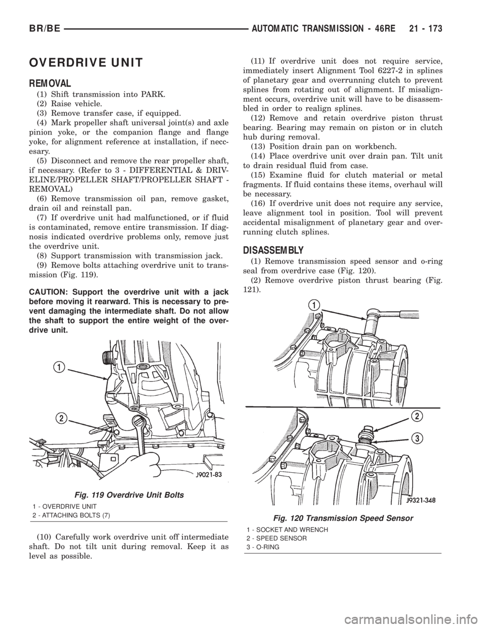
(9) Remove bolts attaching overdrive unit to trans-
mission (Fig. 119).
CAUTION: Support the overdrive unit with a jack
before moving it rearward. This is necessary to pre-
vent damaging the intermediate shaft. Do not allow
the shaft to support the entire weight of the over-
drive unit.
(10) Carefully work overdrive unit off intermediate
shaft. Do not tilt unit during removal. Keep it as
level as possible.(11) If overdrive unit does not require service,
immediately insert Alignment Tool 6227-2 in splines
of planetary gear and overrunning clutch to prevent
splines from rotating out of alignment. If misalign-
ment occurs, overdrive unit will have to be disassem-
bled in order to realign splines.
(12) Remove and retain overdrive piston thrust
bearing. Bearing may remain on piston or in clutch
hub during removal.
(13) Position drain pan on workbench.
(14) Place overdrive unit over drain pan. Tilt unit
to drain residual fluid from case.
(15) Examine fluid for clutch material or metal
fragments. If fluid contains these items, overhaul will
be necessary.
(16) If overdrive unit does not require any service,
leave alignment tool in position. Tool will prevent
accidental misalignment of planetary gear and over-
running clutch splines.
DISASSEMBLY
(1) Remove transmission speed sensor and o-ring
seal from overdrive case (Fig. 120).
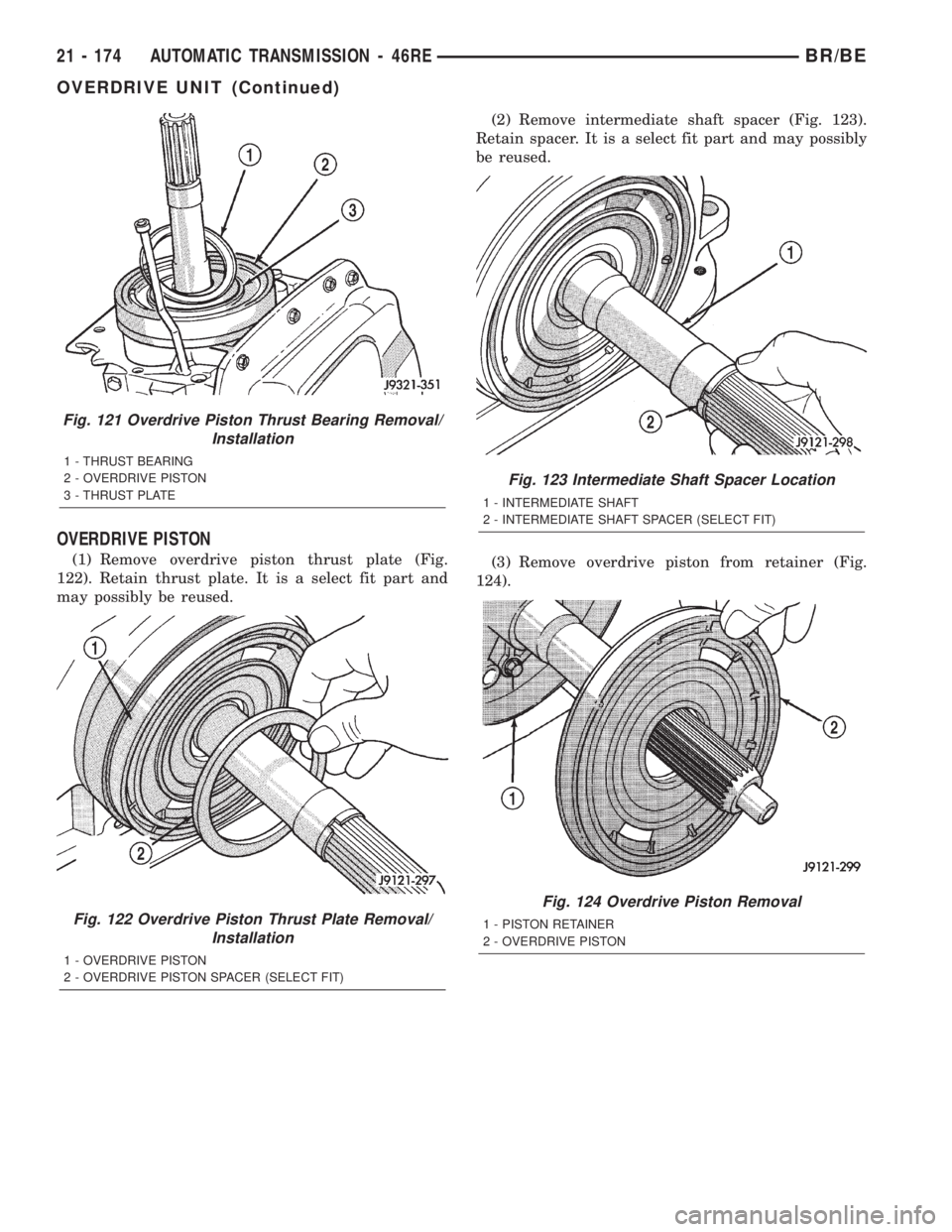
(2) Remove overdrive piston thrust bearing (Fig.
121).
Fig. 119 Overdrive Unit Bolts
1 - OVERDRIVE UNIT
2 - ATTACHING BOLTS (7)
Fig. 120 Transmission Speed Sensor
1 - SOCKET AND WRENCH
2 - SPEED SENSOR
3 - O-RING
BR/BEAUTOMATIC TRANSMISSION - 46RE 21 - 173
Page 1627 of 2255
OVERDRIVE PISTON
(1) Remove overdrive piston thrust plate (Fig.
122). Retain thrust plate. It is a select fit part and
may possibly be reused.(2) Remove intermediate shaft spacer (Fig. 123).
Retain spacer. It is a select fit part and may possibly
be reused.
(3) Remove overdrive piston from retainer (Fig.
124).
Fig. 121 Overdrive Piston Thrust Bearing Removal/
Installation
1 - THRUST BEARING
2 - OVERDRIVE PISTON
3 - THRUST PLATE
Fig. 122 Overdrive Piston Thrust Plate Removal/
Installation
1 - OVERDRIVE PISTON
2 - OVERDRIVE PISTON SPACER (SELECT FIT)
Fig. 123 Intermediate Shaft Spacer Location
1 - INTERMEDIATE SHAFT
2 - INTERMEDIATE SHAFT SPACER (SELECT FIT)
Fig. 124 Overdrive Piston Removal
1 - PISTON RETAINER
2 - OVERDRIVE PISTON
21 - 174 AUTOMATIC TRANSMISSION - 46REBR/BE
OVERDRIVE UNIT (Continued)
Page 1628 of 2255
OVERDRIVE CLUTCH PACK
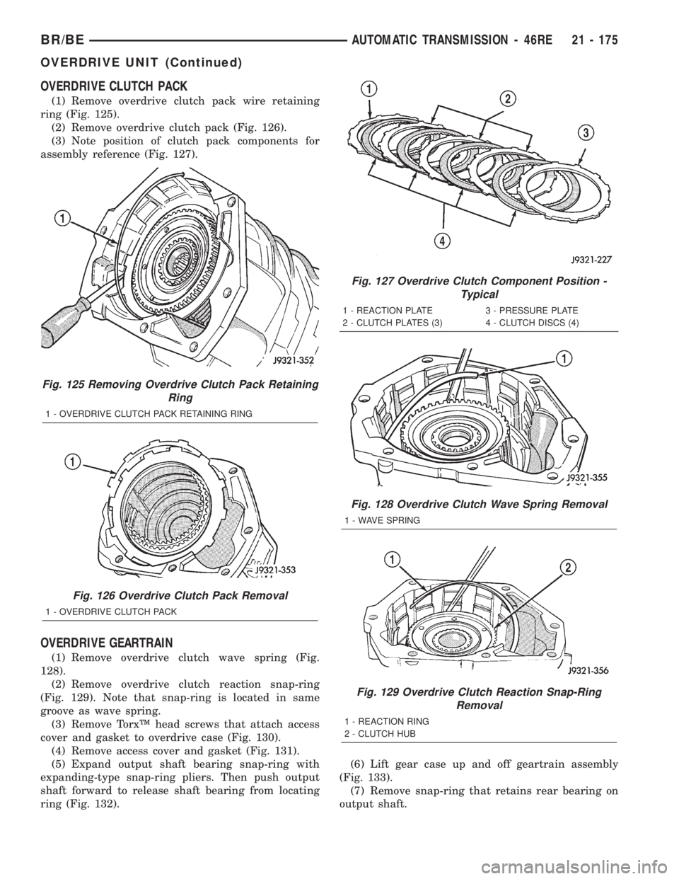
(1) Remove overdrive clutch pack wire retaining
ring (Fig. 125).
(2) Remove overdrive clutch pack (Fig. 126).
(3) Note position of clutch pack components for
assembly reference (Fig. 127).
OVERDRIVE GEARTRAIN
(1) Remove overdrive clutch wave spring (Fig.
128).
(2) Remove overdrive clutch reaction snap-ring
(Fig. 129). Note that snap-ring is located in same
groove as wave spring.
(3) Remove TorxŸ head screws that attach access
cover and gasket to overdrive case (Fig. 130).
(4) Remove access cover and gasket (Fig. 131).
(5) Expand output shaft bearing snap-ring with
expanding-type snap-ring pliers. Then push output
shaft forward to release shaft bearing from locating
ring (Fig. 132).(6) Lift gear case up and off geartrain assembly
(Fig. 133).
(7) Remove snap-ring that retains rear bearing on
output shaft.
Fig. 125 Removing Overdrive Clutch Pack Retaining
Ring
1 - OVERDRIVE CLUTCH PACK RETAINING RING
Fig. 126 Overdrive Clutch Pack Removal
1 - OVERDRIVE CLUTCH PACK
Fig. 127 Overdrive Clutch Component Position -
Typical
1 - REACTION PLATE 3 - PRESSURE PLATE
2 - CLUTCH PLATES (3) 4 - CLUTCH DISCS (4)
Fig. 128 Overdrive Clutch Wave Spring Removal
1 - WAVE SPRING
Fig. 129 Overdrive Clutch Reaction Snap-Ring
Removal
1 - REACTION RING
2 - CLUTCH HUB
BR/BEAUTOMATIC TRANSMISSION - 46RE 21 - 175
OVERDRIVE UNIT (Continued)
Page 1629 of 2255
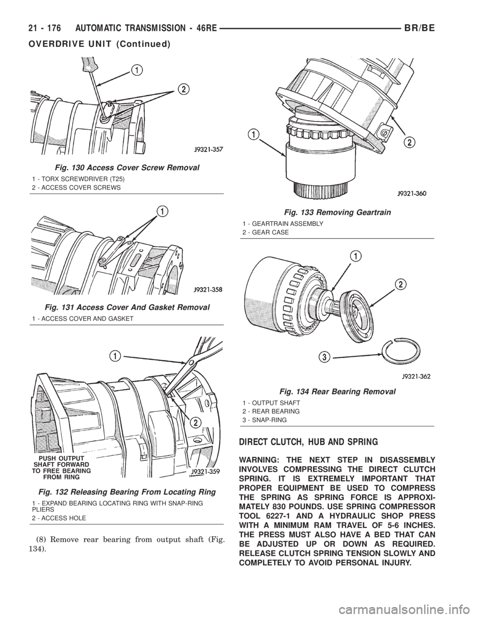
(8) Remove rear bearing from output shaft (Fig.
134).
DIRECT CLUTCH, HUB AND SPRING
WARNING: THE NEXT STEP IN DISASSEMBLY
INVOLVES COMPRESSING THE DIRECT CLUTCH
SPRING. IT IS EXTREMELY IMPORTANT THAT
PROPER EQUIPMENT BE USED TO COMPRESS
THE SPRING AS SPRING FORCE IS APPROXI-
MATELY 830 POUNDS. USE SPRING COMPRESSOR
TOOL 6227-1 AND A HYDRAULIC SHOP PRESS
WITH A MINIMUM RAM TRAVEL OF 5-6 INCHES.
THE PRESS MUST ALSO HAVE A BED THAT CAN
BE ADJUSTED UP OR DOWN AS REQUIRED.
RELEASE CLUTCH SPRING TENSION SLOWLY AND
COMPLETELY TO AVOID PERSONAL INJURY.
Fig. 130 Access Cover Screw Removal
1 - TORX SCREWDRIVER (T25)
2 - ACCESS COVER SCREWS
Fig. 131 Access Cover And Gasket Removal
1 - ACCESS COVER AND GASKET
Fig. 132 Releasing Bearing From Locating Ring
1 - EXPAND BEARING LOCATING RING WITH SNAP-RING
PLIERS
2 - ACCESS HOLE
Fig. 133 Removing Geartrain
1 - GEARTRAIN ASSEMBLY
2 - GEAR CASE
Fig. 134 Rear Bearing Removal
1 - OUTPUT SHAFT
2 - REAR BEARING
3 - SNAP-RING
21 - 176 AUTOMATIC TRANSMISSION - 46REBR/BE
OVERDRIVE UNIT (Continued)
Page 1630 of 2255
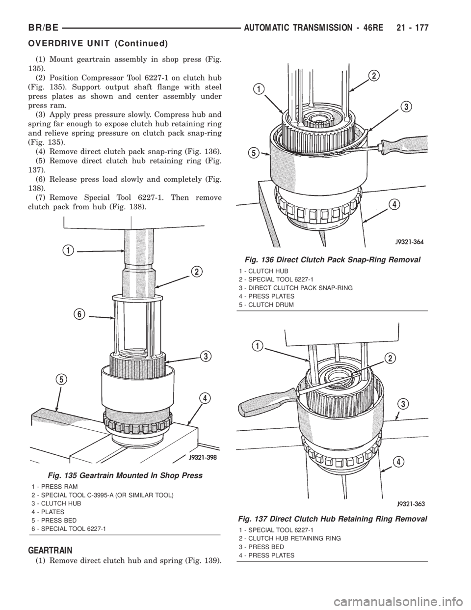
(1) Mount geartrain assembly in shop press (Fig.
135).
(2) Position Compressor Tool 6227-1 on clutch hub
(Fig. 135). Support output shaft flange with steel
press plates as shown and center assembly under
press ram.
(3) Apply press pressure slowly. Compress hub and
spring far enough to expose clutch hub retaining ring
and relieve spring pressure on clutch pack snap-ring
(Fig. 135).
(4) Remove direct clutch pack snap-ring (Fig. 136).
(5) Remove direct clutch hub retaining ring (Fig.
137).
(6) Release press load slowly and completely (Fig.
138).
(7) Remove Special Tool 6227-1. Then remove
clutch pack from hub (Fig. 138).
GEARTRAIN
(1) Remove direct clutch hub and spring (Fig. 139).
Fig. 135 Geartrain Mounted In Shop Press
1 - PRESS RAM
2 - SPECIAL TOOL C-3995-A (OR SIMILAR TOOL)
3 - CLUTCH HUB
4 - PLATES
5 - PRESS BED
6 - SPECIAL TOOL 6227-1
Fig. 136 Direct Clutch Pack Snap-Ring Removal
1 - CLUTCH HUB
2 - SPECIAL TOOL 6227-1
3 - DIRECT CLUTCH PACK SNAP-RING
4 - PRESS PLATES
5 - CLUTCH DRUM
Fig. 137 Direct Clutch Hub Retaining Ring Removal
1 - SPECIAL TOOL 6227-1
2 - CLUTCH HUB RETAINING RING
3 - PRESS BED
4 - PRESS PLATES
BR/BEAUTOMATIC TRANSMISSION - 46RE 21 - 177
OVERDRIVE UNIT (Continued)