DODGE RAM 2002 Service Repair Manual
Manufacturer: DODGE, Model Year: 2002, Model line: RAM, Model: DODGE RAM 2002Pages: 2255, PDF Size: 62.07 MB
Page 1861 of 2255
²Converter clutch/overdrive solenoid assembly
and harness.
²Governor housing gasket.
²Solenoid case connector O-rings.
(1) Shift transmission into NEUTRAL.
(2) Raise vehicle.(3) Remove gearshift and throttle levers from shaft
of valve body manual lever.
(4) Disconnect wires at solenoid case connector
(Fig. 263).
(5) Position drain pan under transmission oil pan.
(6) Remove transmission oil pan and gasket.
(7) Remove fluid filter from valve body.
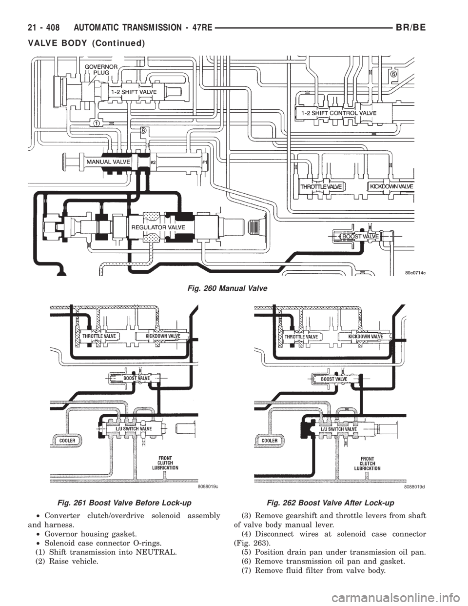
Fig. 260 Manual Valve
Fig. 261 Boost Valve Before Lock-upFig. 262 Boost Valve After Lock-up
21 - 408 AUTOMATIC TRANSMISSION - 47REBR/BE
VALVE BODY (Continued)
Page 1862 of 2255
(8) Remove bolts attaching valve body to transmis-
sion case.
(9) Lower valve body enough to remove accumula-
tor piston and springs.
(10) Work manual lever shaft and electrical con-
nector out of transmission case.
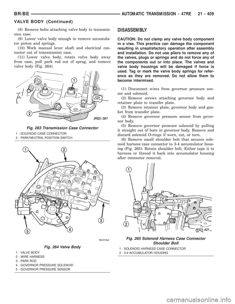
(11) Lower valve body, rotate valve body away
from case, pull park rod out of sprag, and remove
valve body (Fig. 264).DISASSEMBLY
CAUTION: Do not clamp any valve body component
in a vise. This practice can damage the component
resulting in unsatisfactory operation after assembly
and installation. Do not use pliers to remove any of
the valves, plugs or springs and do not force any of
the components out or into place. The valves and
valve body housings will be damaged if force is
used. Tag or mark the valve body springs for refer-
ence as they are removed. Do not allow them to
become intermixed.
(1) Disconnect wires from governor pressure sen-
sor and solenoid.
(2) Remove screws attaching governor body and
retainer plate to transfer plate.
(3) Remove retainer plate, governor body and gas-
ket from transfer plate.
(4) Remove governor pressure sensor from gover-
nor body.
(5) Remove governor pressure solenoid by pulling
it straight out of bore in governor body. Remove and
discard solenoid O-rings if worn, cut, or torn.
(6) Remove small shoulder bolt that secures sole-
noid harness case connector to 3-4 accumulator hous-
ing (Fig. 265). Retain shoulder bolt. Either tape it to
harness or thread it back into accumulator housing
after connector removal.
Fig. 263 Transmission Case Connector
1 - SOLENOID CASE CONNECTOR
2 - PARK/NEUTRAL POSITION SWITCH
Fig. 264 Valve Body
1 - VALVE BODY
2 - WIRE HARNESS
3 - PARK ROD
4 - GOVERNOR PRESSURE SOLENOID
5 - GOVERNOR PRESSURE SENSOR
Fig. 265 Solenoid Harness Case Connector
Shoulder Bolt
1 - SOLENOID HARNESS CASE CONNECTOR
2 - 3-4 ACCUMULATOR HOUSING
BR/BEAUTOMATIC TRANSMISSION - 47RE 21 - 409
VALVE BODY (Continued)
Page 1863 of 2255
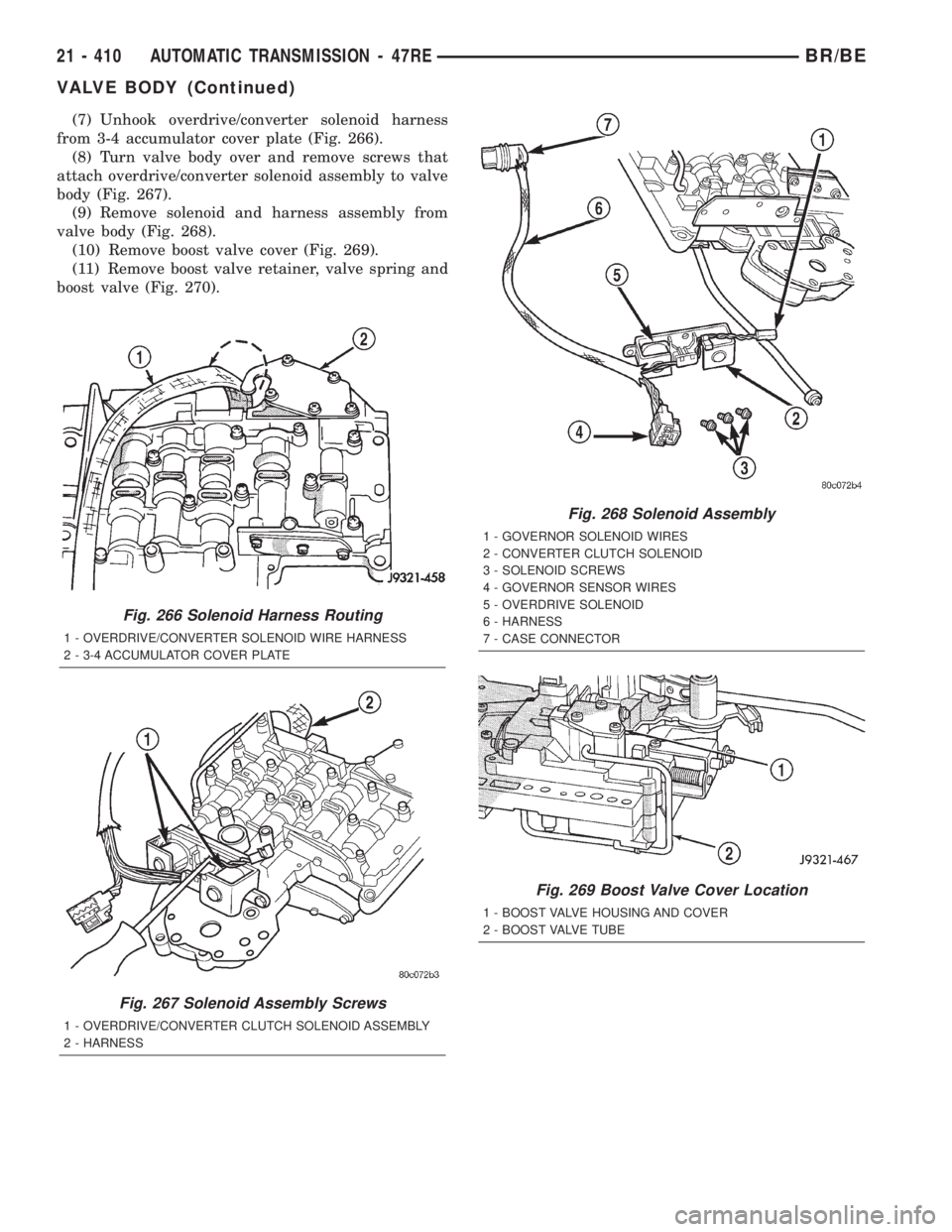
(7) Unhook overdrive/converter solenoid harness
from 3-4 accumulator cover plate (Fig. 266).
(8) Turn valve body over and remove screws that
attach overdrive/converter solenoid assembly to valve
body (Fig. 267).
(9) Remove solenoid and harness assembly from
valve body (Fig. 268).
(10) Remove boost valve cover (Fig. 269).
(11) Remove boost valve retainer, valve spring and
boost valve (Fig. 270).
Fig. 266 Solenoid Harness Routing
1 - OVERDRIVE/CONVERTER SOLENOID WIRE HARNESS
2 - 3-4 ACCUMULATOR COVER PLATE
Fig. 267 Solenoid Assembly Screws
1 - OVERDRIVE/CONVERTER CLUTCH SOLENOID ASSEMBLY
2 - HARNESS
Fig. 268 Solenoid Assembly
1 - GOVERNOR SOLENOID WIRES
2 - CONVERTER CLUTCH SOLENOID
3 - SOLENOID SCREWS
4 - GOVERNOR SENSOR WIRES
5 - OVERDRIVE SOLENOID
6 - HARNESS
7 - CASE CONNECTOR
Fig. 269 Boost Valve Cover Location
1 - BOOST VALVE HOUSING AND COVER
2 - BOOST VALVE TUBE
21 - 410 AUTOMATIC TRANSMISSION - 47REBR/BE
VALVE BODY (Continued)
Page 1864 of 2255
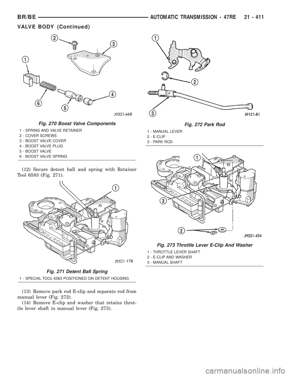
(12) Secure detent ball and spring with Retainer
Tool 6583 (Fig. 271).
(13) Remove park rod E-clip and separate rod from
manual lever (Fig. 272).
(14) Remove E-clip and washer that retains throt-
tle lever shaft in manual lever (Fig. 273).
Fig. 270 Boost Valve Components
1 - SPRING AND VALVE RETAINER
2 - COVER SCREWS
3 - BOOST VALVE COVER
4 - BOOST VALVE PLUG
5 - BOOST VALVE
6 - BOOST VALVE SPRING
Fig. 271 Detent Ball Spring
1 - SPECIAL TOOL 6583 POSITIONED ON DETENT HOUSING
Fig. 272 Park Rod
1 - MANUAL LEVER
2 - E-CLIP
3 - PARK ROD
Fig. 273 Throttle Lever E-Clip And Washer
1 - THROTTLE LEVER SHAFT
2 - E-CLIP AND WASHER
3 - MANUAL SHAFT
BR/BEAUTOMATIC TRANSMISSION - 47RE 21 - 411
VALVE BODY (Continued)
Page 1865 of 2255
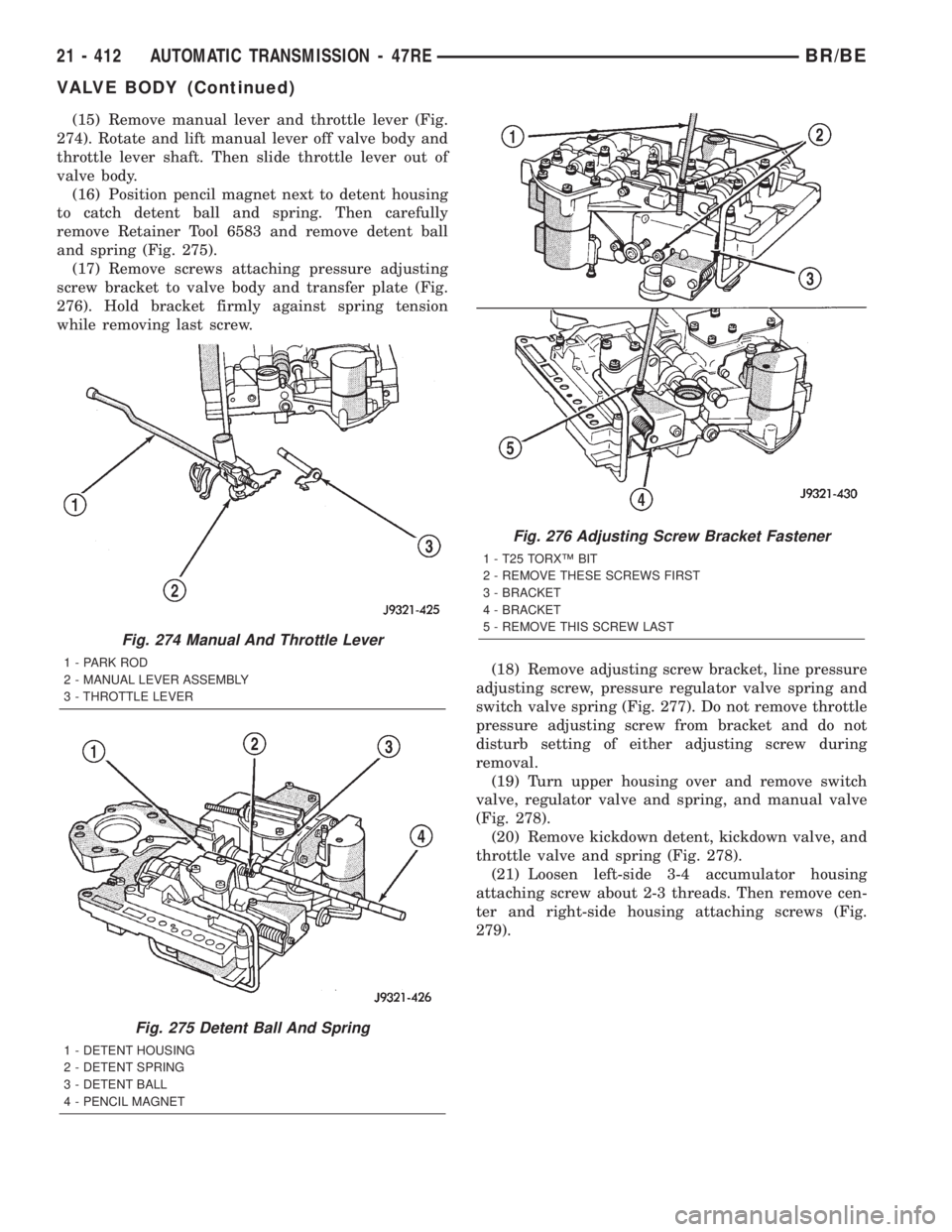
(15) Remove manual lever and throttle lever (Fig.
274). Rotate and lift manual lever off valve body and
throttle lever shaft. Then slide throttle lever out of
valve body.
(16) Position pencil magnet next to detent housing
to catch detent ball and spring. Then carefully
remove Retainer Tool 6583 and remove detent ball
and spring (Fig. 275).
(17) Remove screws attaching pressure adjusting
screw bracket to valve body and transfer plate (Fig.
276). Hold bracket firmly against spring tension
while removing last screw.
(18) Remove adjusting screw bracket, line pressure
adjusting screw, pressure regulator valve spring and
switch valve spring (Fig. 277). Do not remove throttle
pressure adjusting screw from bracket and do not
disturb setting of either adjusting screw during
removal.
(19) Turn upper housing over and remove switch
valve, regulator valve and spring, and manual valve
(Fig. 278).
(20) Remove kickdown detent, kickdown valve, and
throttle valve and spring (Fig. 278).
(21) Loosen left-side 3-4 accumulator housing
attaching screw about 2-3 threads. Then remove cen-
ter and right-side housing attaching screws (Fig.
279).
Fig. 274 Manual And Throttle Lever
1 - PARK ROD
2 - MANUAL LEVER ASSEMBLY
3 - THROTTLE LEVER
Fig. 275 Detent Ball And Spring
1 - DETENT HOUSING
2 - DETENT SPRING
3 - DETENT BALL
4 - PENCIL MAGNET
Fig. 276 Adjusting Screw Bracket Fastener
1 - T25 TORXŸ BIT
2 - REMOVE THESE SCREWS FIRST
3 - BRACKET
4 - BRACKET
5 - REMOVE THIS SCREW LAST
21 - 412 AUTOMATIC TRANSMISSION - 47REBR/BE
VALVE BODY (Continued)
Page 1866 of 2255
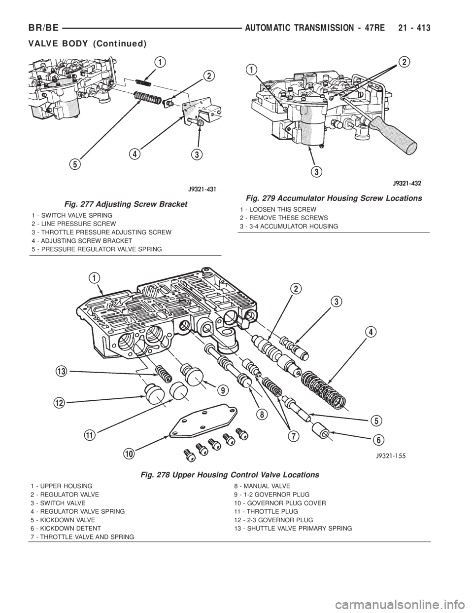
Fig. 277 Adjusting Screw Bracket
1 - SWITCH VALVE SPRING
2 - LINE PRESSURE SCREW
3 - THROTTLE PRESSURE ADJUSTING SCREW
4 - ADJUSTING SCREW BRACKET
5 - PRESSURE REGULATOR VALVE SPRING
Fig. 278 Upper Housing Control Valve Locations
1 - UPPER HOUSING 8 - MANUAL VALVE
2 - REGULATOR VALVE 9 - 1-2 GOVERNOR PLUG
3 - SWITCH VALVE 10 - GOVERNOR PLUG COVER
4 - REGULATOR VALVE SPRING 11 - THROTTLE PLUG
5 - KICKDOWN VALVE 12 - 2-3 GOVERNOR PLUG
6 - KICKDOWN DETENT 13 - SHUTTLE VALVE PRIMARY SPRING
7 - THROTTLE VALVE AND SPRING
Fig. 279 Accumulator Housing Screw Locations
1 - LOOSEN THIS SCREW
2 - REMOVE THESE SCREWS
3 - 3-4 ACCUMULATOR HOUSING
BR/BEAUTOMATIC TRANSMISSION - 47RE 21 - 413
VALVE BODY (Continued)
Page 1867 of 2255
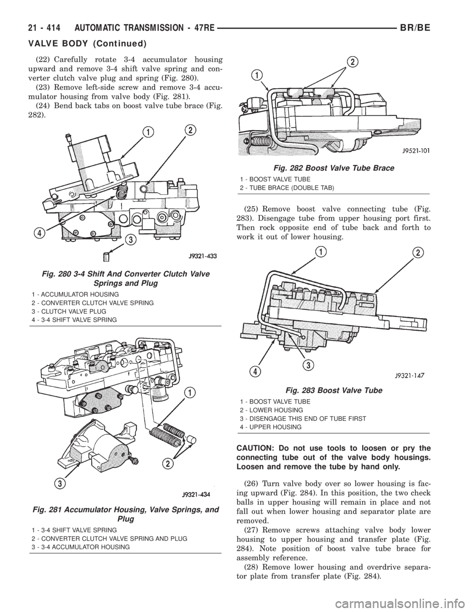
(22) Carefully rotate 3-4 accumulator housing
upward and remove 3-4 shift valve spring and con-
verter clutch valve plug and spring (Fig. 280).
(23) Remove left-side screw and remove 3-4 accu-
mulator housing from valve body (Fig. 281).
(24) Bend back tabs on boost valve tube brace (Fig.
282).
(25) Remove boost valve connecting tube (Fig.
283). Disengage tube from upper housing port first.
Then rock opposite end of tube back and forth to
work it out of lower housing.
CAUTION: Do not use tools to loosen or pry the
connecting tube out of the valve body housings.
Loosen and remove the tube by hand only.
(26) Turn valve body over so lower housing is fac-
ing upward (Fig. 284). In this position, the two check
balls in upper housing will remain in place and not
fall out when lower housing and separator plate are
removed.
(27) Remove screws attaching valve body lower
housing to upper housing and transfer plate (Fig.
284). Note position of boost valve tube brace for
assembly reference.
(28) Remove lower housing and overdrive separa-
tor plate from transfer plate (Fig. 284).
Fig. 280 3-4 Shift And Converter Clutch Valve
Springs and Plug
1 - ACCUMULATOR HOUSING
2 - CONVERTER CLUTCH VALVE SPRING
3 - CLUTCH VALVE PLUG
4 - 3-4 SHIFT VALVE SPRING
Fig. 281 Accumulator Housing, Valve Springs, and
Plug
1 - 3-4 SHIFT VALVE SPRING
2 - CONVERTER CLUTCH VALVE SPRING AND PLUG
3 - 3-4 ACCUMULATOR HOUSING
Fig. 282 Boost Valve Tube Brace
1 - BOOST VALVE TUBE
2 - TUBE BRACE (DOUBLE TAB)
Fig. 283 Boost Valve Tube
1 - BOOST VALVE TUBE
2 - LOWER HOUSING
3 - DISENGAGE THIS END OF TUBE FIRST
4 - UPPER HOUSING
21 - 414 AUTOMATIC TRANSMISSION - 47REBR/BE
VALVE BODY (Continued)
Page 1868 of 2255
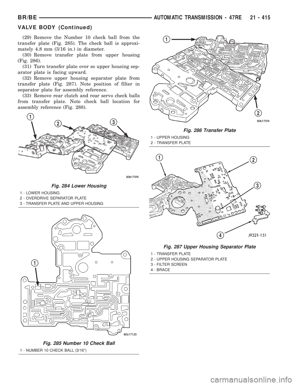
(29) Remove the Number 10 check ball from the
transfer plate (Fig. 285). The check ball is approxi-
mately 4.8 mm (3/16 in.) in diameter.
(30) Remove transfer plate from upper housing
(Fig. 286).
(31) Turn transfer plate over so upper housing sep-
arator plate is facing upward.
(32) Remove upper housing separator plate from
transfer plate (Fig. 287). Note position of filter in
separator plate for assembly reference.
(33) Remove rear clutch and rear servo check balls
from transfer plate. Note check ball location for
assembly reference (Fig. 288).
Fig. 284 Lower Housing
1 - LOWER HOUSING
2 - OVERDRIVE SEPARATOR PLATE
3 - TRANSFER PLATE AND UPPER HOUSING
Fig. 285 Number 10 Check Ball
1 - NUMBER 10 CHECK BALL (3/169)
Fig. 286 Transfer Plate
1 - UPPER HOUSING
2 - TRANSFER PLATE
Fig. 287 Upper Housing Separator Plate
1 - TRANSFER PLATE
2 - UPPER HOUSING SEPARATOR PLATE
3 - FILTER SCREEN
4 - BRACE
BR/BEAUTOMATIC TRANSMISSION - 47RE 21 - 415
VALVE BODY (Continued)
Page 1869 of 2255
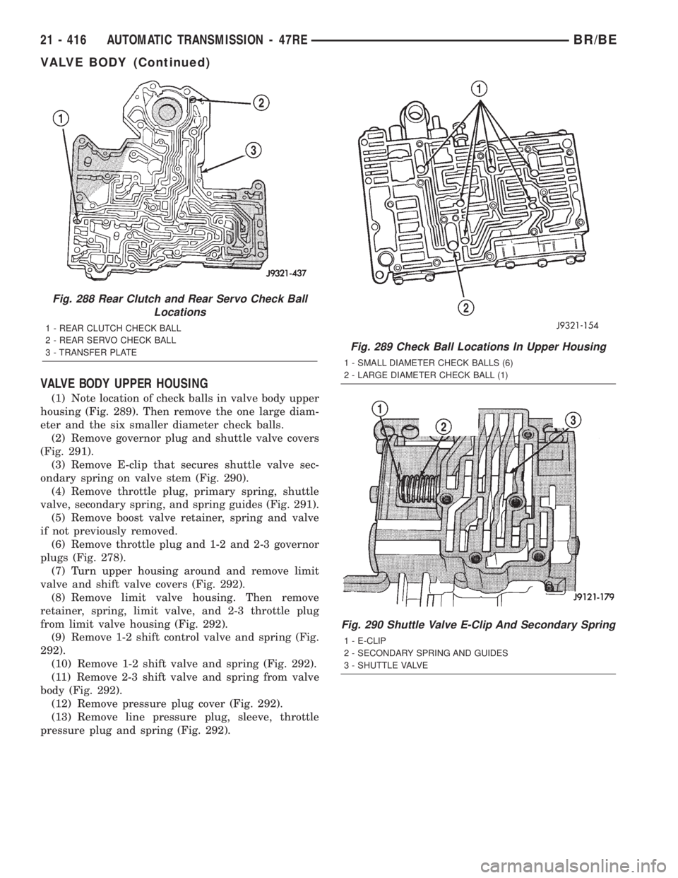
VALVE BODY UPPER HOUSING
(1) Note location of check balls in valve body upper
housing (Fig. 289). Then remove the one large diam-
eter and the six smaller diameter check balls.
(2) Remove governor plug and shuttle valve covers
(Fig. 291).
(3) Remove E-clip that secures shuttle valve sec-
ondary spring on valve stem (Fig. 290).
(4) Remove throttle plug, primary spring, shuttle
valve, secondary spring, and spring guides (Fig. 291).
(5) Remove boost valve retainer, spring and valve
if not previously removed.
(6) Remove throttle plug and 1-2 and 2-3 governor
plugs (Fig. 278).
(7) Turn upper housing around and remove limit
valve and shift valve covers (Fig. 292).
(8) Remove limit valve housing. Then remove
retainer, spring, limit valve, and 2-3 throttle plug
from limit valve housing (Fig. 292).
(9) Remove 1-2 shift control valve and spring (Fig.
292).
(10) Remove 1-2 shift valve and spring (Fig. 292).
(11) Remove 2-3 shift valve and spring from valve
body (Fig. 292).
(12) Remove pressure plug cover (Fig. 292).
(13) Remove line pressure plug, sleeve, throttle
pressure plug and spring (Fig. 292).
Fig. 288 Rear Clutch and Rear Servo Check Ball
Locations
1 - REAR CLUTCH CHECK BALL
2 - REAR SERVO CHECK BALL
3 - TRANSFER PLATE
Fig. 289 Check Ball Locations In Upper Housing
1 - SMALL DIAMETER CHECK BALLS (6)
2 - LARGE DIAMETER CHECK BALL (1)
Fig. 290 Shuttle Valve E-Clip And Secondary Spring
1 - E-CLIP
2 - SECONDARY SPRING AND GUIDES
3 - SHUTTLE VALVE
21 - 416 AUTOMATIC TRANSMISSION - 47REBR/BE
VALVE BODY (Continued)
Page 1870 of 2255
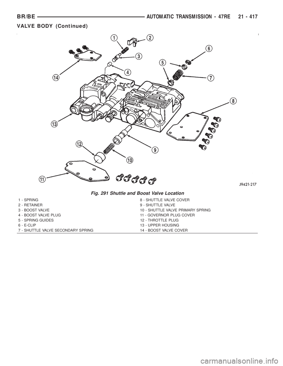
Fig. 291 Shuttle and Boost Valve Location
1 - SPRING 8 - SHUTTLE VALVE COVER
2 - RETAINER 9 - SHUTTLE VALVE
3 - BOOST VALVE 10 - SHUTTLE VALVE PRIMARY SPRING
4 - BOOST VALVE PLUG 11 - GOVERNOR PLUG COVER
5 - SPRING GUIDES 12 - THROTTLE PLUG
6 - E-CLIP 13 - UPPER HOUSING
7 - SHUTTLE VALVE SECONDARY SPRING 14 - BOOST VALVE COVER
BR/BEAUTOMATIC TRANSMISSION - 47RE 21 - 417
VALVE BODY (Continued)