DODGE RAM 2002 Service Repair Manual
Manufacturer: DODGE, Model Year: 2002, Model line: RAM, Model: DODGE RAM 2002Pages: 2255, PDF Size: 62.07 MB
Page 2051 of 2255
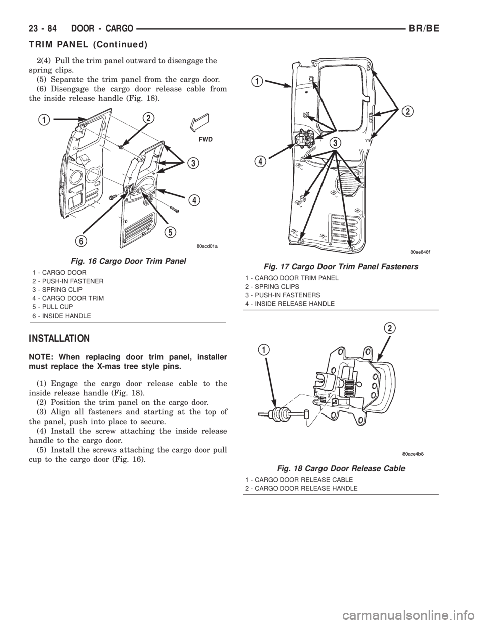
2(4) Pull the trim panel outward to disengage the
spring clips.
(5) Separate the trim panel from the cargo door.
(6) Disengage the cargo door release cable from
the inside release handle (Fig. 18).
INSTALLATION
NOTE: When replacing door trim panel, installer
must replace the X-mas tree style pins.
(1) Engage the cargo door release cable to the
inside release handle (Fig. 18).
(2) Position the trim panel on the cargo door.
(3) Align all fasteners and starting at the top of
the panel, push into place to secure.
(4) Install the screw attaching the inside release
handle to the cargo door.
(5) Install the screws attaching the cargo door pull
cup to the cargo door (Fig. 16).
Fig. 16 Cargo Door Trim Panel
1 - CARGO DOOR
2 - PUSH-IN FASTENER
3 - SPRING CLIP
4 - CARGO DOOR TRIM
5 - PULL CUP
6 - INSIDE HANDLEFig. 17 Cargo Door Trim Panel Fasteners
1 - CARGO DOOR TRIM PANEL
2 - SPRING CLIPS
3 - PUSH-IN FASTENERS
4 - INSIDE RELEASE HANDLE
Fig. 18 Cargo Door Release Cable
1 - CARGO DOOR RELEASE CABLE
2 - CARGO DOOR RELEASE HANDLE
23 - 84 DOOR - CARGOBR/BE
TRIM PANEL (Continued)
Page 2052 of 2255
VENT WINDOW
REMOVAL
(1) Remove cargo door trim panel (Refer to 23 -
BODY/DOOR - CARGO/TRIM PANEL - REMOVAL).
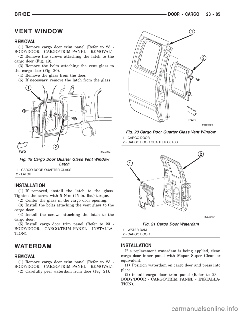
(2) Remove the screws attaching the latch to the
cargo door (Fig. 19).
(3) Remove the bolts attaching the vent glass to
the cargo door (Fig. 20).
(4) Remove the glass from the door.
(5) If necessary, remove the latch from the glass.
INSTALLATION
(1) If removed, install the latch to the glass.
Tighten the screw with 5 N´m (45 in. lbs.) torque.
(2) Center the glass in the cargo door opening.
(3) Install the bolts attaching the vent glass to the
cargo door.
(4) Install the screws attaching the latch to the
cargo door.
(5) Install cargo door trim panel (Refer to 23 -
BODY/DOOR - CARGO/TRIM PANEL - INSTALLA-
TION).
WATERDAM
REMOVAL
(1) Remove cargo door trim panel (Refer to 23 -
BODY/DOOR - CARGO/TRIM PANEL - REMOVAL).
(2) Carefully peel waterdam from door (Fig. 21).
INSTALLATION
If a replacement waterdam is being applied, clean
cargo door inner panel with Mopar Super Clean or
equivalent.
(1) Position waterdam on cargo door and press into
place.
(2) install cargo door trim panel (Refer to 23 -
BODY/DOOR - CARGO/TRIM PANEL - INSTALLA-
TION).
Fig. 19 Cargo Door Quarter Glass Vent Window
Latch
1 - CARGO DOOR QUARTER GLASS
2-LATCH
Fig. 20 Cargo Door Quarter Glass Vent Window
1 - CARGO DOOR
2 - CARGO DOOR QUARTER GLASS
Fig. 21 Cargo Door Waterdam
1 - WATER DAM
2 - CARGO DOOR
BR/BEDOOR - CARGO 23 - 85
Page 2053 of 2255
EXTERIOR
TABLE OF CONTENTS
page page
EXTERIOR
DESCRIPTION.........................86
OPERATION...........................86
BODY SIDE MOLDINGS
REMOVAL.............................86
INSTALLATION.........................87
BODY STRIPES AND DECALS
REMOVAL.............................87
INSTALLATION.........................87
TAPE STRIPE
REMOVAL.............................88
INSTALLATION.........................89
EXTERIOR NAME PLATES
REMOVAL.............................89
INSTALLATION.........................89
COWL GRILLE
REMOVAL.............................90
INSTALLATION.........................90
ROOF JOINT MOLDING
REMOVAL.............................91
INSTALLATION.........................91
GRILLE
REMOVAL.............................91
INSTALLATION.........................91
GRILLE FRAME
REMOVAL.............................91
INSTALLATION.........................92
FRONT END SPLASH SHIELDS
REMOVAL.............................92
INSTALLATION.........................92LEFT FRONT FENDER
REMOVAL.............................93
INSTALLATION.........................93
RIGHT FRONT FENDER
REMOVAL.............................94
INSTALLATION.........................94
FUEL FILL DOOR
REMOVAL.............................95
INSTALLATION.........................95
REAR FENDER
REMOVAL.............................95
INSTALLATION.........................95
REAR SPLASH SHIELD
REMOVAL.............................96
INSTALLATION.........................96
REAR WHEELHOUSE LINER
REMOVAL.............................96
INSTALLATION.........................96
CARGO BOX
REMOVAL.............................97
INSTALLATION.........................97
SIDE VIEW MIRROR
REMOVAL.............................97
INSTALLATION.........................98
SIDE VIEW MIRROR - LOW MOUNTED
REMOVAL.............................98
INSTALLATION.........................98
SIDE VIEW MIRROR GLASS
REMOVAL.............................98
INSTALLATION.........................98
EXTERIOR
DESCRIPTION
Exterior sheet metal components make up the
exterior of the vehicle. Some exterior metal systems
are welded assemblies, such as doors and hoods.
Some exterior trim items are made of composite.
OPERATION
The exterior is finished in various metal stampings
and composite moldings. These assemblies give the
vehicle a finished appearance and protect the occu-
pants from the elements. Some components are part
of the energy absorbing system used to protect the
occupants in collisions. The exterior sheet metal is
repairable and adjustable for fit and finish. Welded
and bonded component systems are adjustable as asystem. Trim components made of composite are
stamped with the type of material used.
DaimlerChrysler uses various fasteners to retain
trim items. At times, it is not possible to remove trim
items without damaging the fastener. If it is not pos-
sible to remove an item without damaging a compo-
nent, cut or break the fasteners and use new ones
when installing the component.BODY SIDE MOLDINGS
REMOVAL
(1) Warm the effected stick-on molding and body
metal to approximately 38ÉC (100ÉF) using a suitable
heat lamp or heat gun.
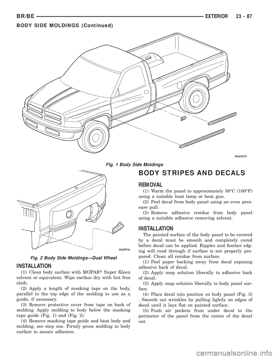
(2) Pull stick-on molding from painted surface
(Fig. 1) and (Fig. 2).
23 - 86 EXTERIORBR/BE
Page 2054 of 2255
INSTALLATION
(1) Clean body surface with MOPARtSuper Kleen
solvent or equivalent. Wipe surface dry with lint free
cloth.
(2) Apply a length of masking tape on the body,
parallel to the top edge of the molding to use as a
guide, if necessary.
(3) Remove protective cover from tape on back of
molding. Apply molding to body below the masking
tape guide (Fig. 1) and (Fig. 2).
(4) Remove masking tape guide and heat body and
molding, see step one. Firmly press molding to body
surface to assure adhesion.
BODY STRIPES AND DECALS
REMOVAL
(1) Warm the panel to approximately 38ÉC (100ÉF)
using a suitable heat lamp or heat gun.
(2) Peel decal from body panel using an even pres-
sure pull.
(3) Remove adhesive residue from body panel
using a suitable adhesive removing solvent.
INSTALLATION
The painted surface of the body panel to be covered
by a decal must be smooth and completely cured
before decal can be applied. Ripples and feather edg-
ing will read through if surface is not properly pre-
pared. Clean all residue from surface.
(1) Peel paper backing away from decal exposing
adhesive back of decal.
(2) Apply soap solution liberally to adhesive back
of decal.
(3) Apply soap solution liberally to body panel sur-
face.
(4) Place decal into position on body panel (Fig. 3)
. Smooth out wrinkles by pulling lightly on edges of
decal until it lays flat on painted surface.
(5) Push air pockets from under decal to the
perimeter of the panel from the center of the decal
out.
Fig. 1 Body Side Moldings
Fig. 2 Body Side MoldingsÐDual Wheel
BR/BEEXTERIOR 23 - 87
BODY SIDE MOLDINGS (Continued)
Page 2055 of 2255
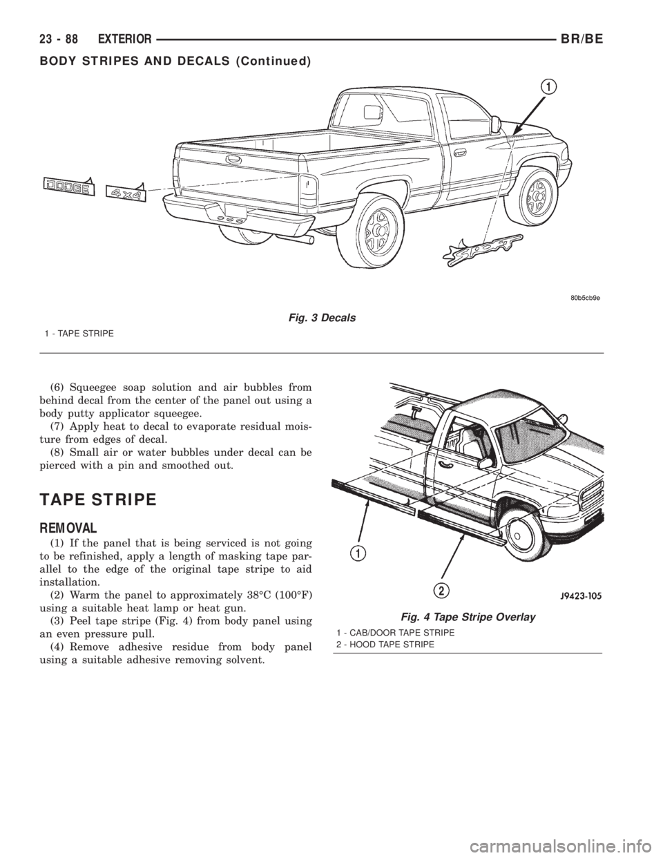
(6) Squeegee soap solution and air bubbles from
behind decal from the center of the panel out using a
body putty applicator squeegee.
(7) Apply heat to decal to evaporate residual mois-
ture from edges of decal.
(8) Small air or water bubbles under decal can be
pierced with a pin and smoothed out.
TAPE STRIPE
REMOVAL
(1) If the panel that is being serviced is not going
to be refinished, apply a length of masking tape par-
allel to the edge of the original tape stripe to aid
installation.
(2) Warm the panel to approximately 38ÉC (100ÉF)
using a suitable heat lamp or heat gun.
(3) Peel tape stripe (Fig. 4) from body panel using
an even pressure pull.
(4) Remove adhesive residue from body panel
using a suitable adhesive removing solvent.
Fig. 3 Decals
1 - TAPE STRIPE
Fig. 4 Tape Stripe Overlay
1 - CAB/DOOR TAPE STRIPE
2 - HOOD TAPE STRIPE
23 - 88 EXTERIORBR/BE
BODY STRIPES AND DECALS (Continued)
Page 2056 of 2255
INSTALLATION
The painted surface of the body panel to be covered
by a tape stripe overlay must be smooth and com-
pletely cured before overlay can be applied. If painted
surface is not smooth, wet sand with 600 grit wet/dry
sand paper until surface is smooth. Ripples and
feather edging will read through overlay if surface is
not properly prepared. Clean all residue from sur-
face.
Installation equipment:
²Pail filled with mild dish soap solution.
²Lint free applicator cloth or sponge.
²Body putty applicator squeegee.
²Heat gun or sun lamp.
²Razor knife.
(1) Spread replacement tape stripe overlay across
a smooth flat work surface, finish side down.
(2) Peel paper backing away from overlay exposing
adhesive back of overlay.
(3) Apply soap solution liberally to adhesive back
of overlay.
(4) Apply soap solution liberally to body panel sur-
face.
(5) Place overlay into position on body panel.
Smooth out wrinkles by pulling lightly on edges of
overlay until it lays flat on painted surface.
(6) Push air pockets from under overlay to the
perimeter of the panel from the center of the overlay
out.
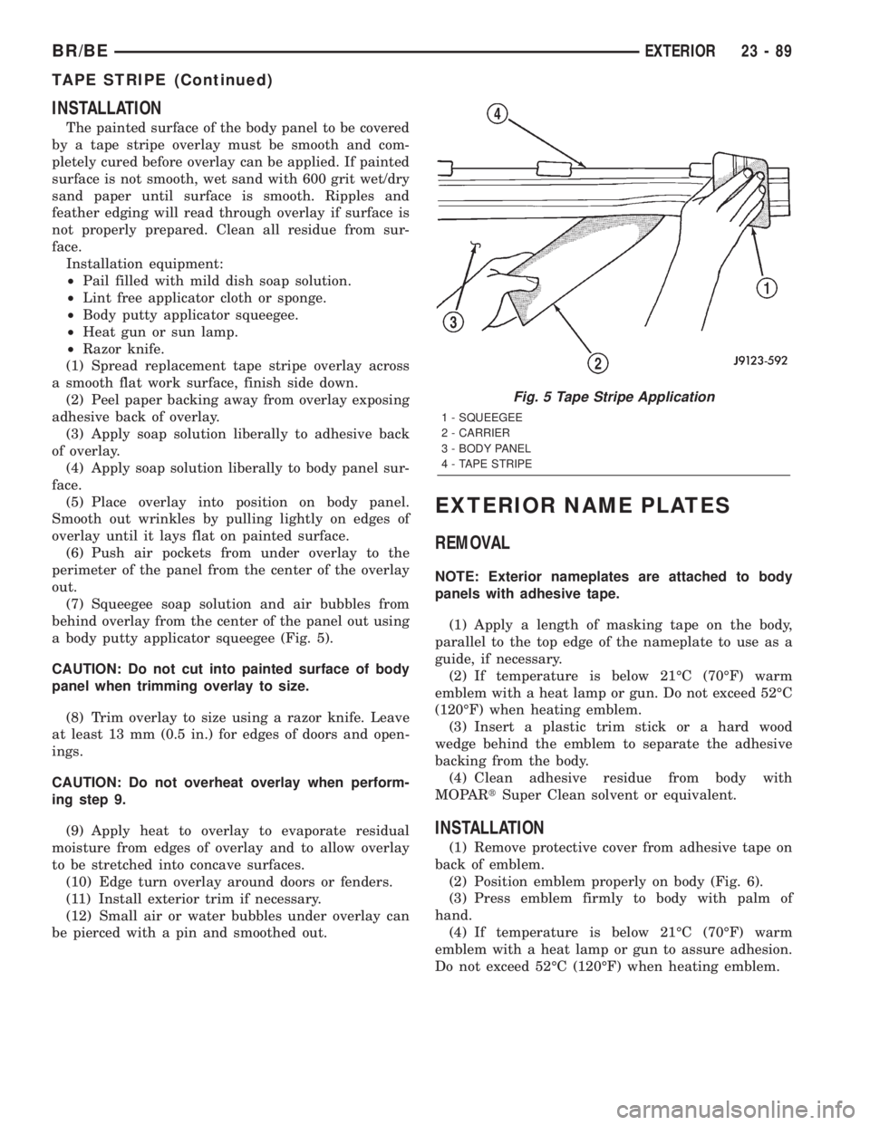
(7) Squeegee soap solution and air bubbles from
behind overlay from the center of the panel out using
a body putty applicator squeegee (Fig. 5).
CAUTION: Do not cut into painted surface of body
panel when trimming overlay to size.
(8) Trim overlay to size using a razor knife. Leave
at least 13 mm (0.5 in.) for edges of doors and open-
ings.
CAUTION: Do not overheat overlay when perform-
ing step 9.
(9) Apply heat to overlay to evaporate residual
moisture from edges of overlay and to allow overlay
to be stretched into concave surfaces.
(10) Edge turn overlay around doors or fenders.
(11) Install exterior trim if necessary.
(12) Small air or water bubbles under overlay can
be pierced with a pin and smoothed out.
EXTERIOR NAME PLATES
REMOVAL
NOTE: Exterior nameplates are attached to body
panels with adhesive tape.
(1) Apply a length of masking tape on the body,
parallel to the top edge of the nameplate to use as a
guide, if necessary.
(2) If temperature is below 21ÉC (70ÉF) warm
emblem with a heat lamp or gun. Do not exceed 52ÉC
(120ÉF) when heating emblem.
(3) Insert a plastic trim stick or a hard wood
wedge behind the emblem to separate the adhesive
backing from the body.
(4) Clean adhesive residue from body with
MOPARtSuper Clean solvent or equivalent.
INSTALLATION
(1) Remove protective cover from adhesive tape on
back of emblem.
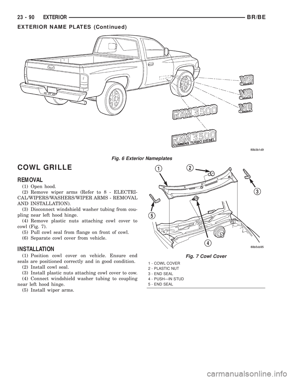
(2) Position emblem properly on body (Fig. 6).
(3) Press emblem firmly to body with palm of
hand.
(4) If temperature is below 21ÉC (70ÉF) warm
emblem with a heat lamp or gun to assure adhesion.
Do not exceed 52ÉC (120ÉF) when heating emblem.
Fig. 5 Tape Stripe Application
1 - SQUEEGEE
2 - CARRIER
3 - BODY PANEL
4 - TAPE STRIPE
BR/BEEXTERIOR 23 - 89
TAPE STRIPE (Continued)
Page 2057 of 2255
COWL GRILLE
REMOVAL
(1) Open hood.
(2) Remove wiper arms (Refer to 8 - ELECTRI-
CAL/WIPERS/WASHERS/WIPER ARMS - REMOVAL
AND INSTALLATION).
(3) Disconnect windshield washer tubing from cou-
pling near left hood hinge.
(4) Remove plastic nuts attaching cowl cover to
cowl (Fig. 7).
(5) Pull cowl seal from flange on front of cowl.
(6) Separate cowl cover from vehicle.
INSTALLATION
(1) Position cowl cover on vehicle. Ensure end
seals are positioned correctly and in good condition.
(2) Install cowl seal.
(3) Install plastic nuts attaching cowl cover to cow.
(4) Connect windshield washer tubing to coupling
near left hood hinge.
(5) Install wiper arms.
Fig. 6 Exterior Nameplates
Fig. 7 Cowl Cover
1 - COWL COVER
2 - PLASTIC NUT
3 - END SEAL
4 - PUSHÐIN STUD
5 - END SEAL
23 - 90 EXTERIORBR/BE
EXTERIOR NAME PLATES (Continued)
Page 2058 of 2255
ROOF JOINT MOLDING
REMOVAL
(1) Warm the roof joint molding and roof panel to
approximately 38ÉC (100ÉF) using a suitable heat
lamp or heat gun.
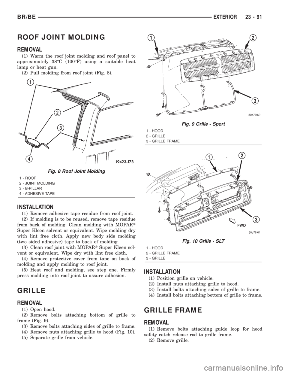
(2) Pull molding from roof joint (Fig. 8).
INSTALLATION
(1) Remove adhesive tape residue from roof joint.
(2) If molding is to be reused, remove tape residue
from back of molding. Clean molding with MOPARt
Super Kleen solvent or equivalent. Wipe molding dry
with lint free cloth. Apply new body side molding
(two sided adhesive) tape to back of molding.
(3) Clean roof joint with MOPARtSuper Kleen sol-
vent or equivalent. Wipe dry with lint free cloth.
(4) Remove protective cover from tape on back of
molding and apply molding to roof joint.
(5) Heat roof and molding, see step one. Firmly
press molding into roof joint to assure adhesion.
GRILLE
REMOVAL
(1) Open hood.
(2) Remove bolts attaching bottom of grille to
frame (Fig. 9).
(3) Remove bolts attaching sides of grille to frame.
(4) Remove nuts attaching grille to hood (Fig. 10).
(5) Separate grille from vehicle.
INSTALLATION
(1) Position grille on vehicle.
(2) Install nuts attaching grille to hood.
(3) Install bolts attaching sides of grille to frame.
(4) Install bolts attaching bottom of grille to frame.
GRILLE FRAME
REMOVAL
(1) Remove bolts attaching guide loop for hood
safety catch release rod to grille frame.
(2) Remove grille.
Fig. 8 Roof Joint Molding
1 - ROOF
2 - JOINT MOLDING
3 - B-PILLAR
4 - ADHESIVE TAPE
Fig. 9 Grille - Sport
1 - HOOD
2 - GRILLE
3 - GRILLE FRAME
Fig. 10 Grille - SLT
1 - HOOD
2 - GRILLE FRAME
3 - GRILLE
BR/BEEXTERIOR 23 - 91
Page 2059 of 2255
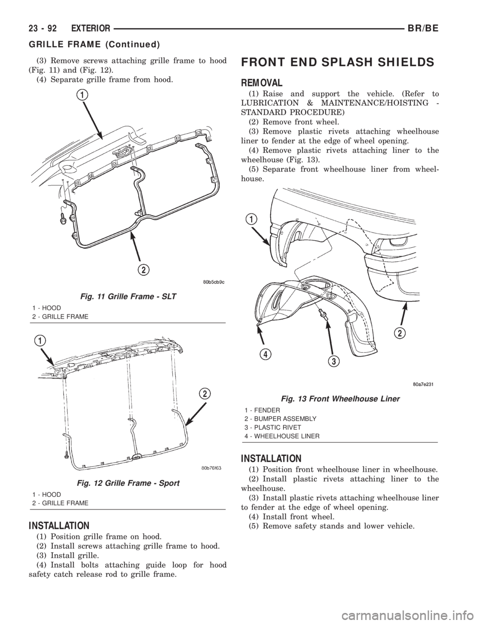
(3) Remove screws attaching grille frame to hood
(Fig. 11) and (Fig. 12).
(4) Separate grille frame from hood.
INSTALLATION
(1) Position grille frame on hood.
(2) Install screws attaching grille frame to hood.
(3) Install grille.
(4) Install bolts attaching guide loop for hood
safety catch release rod to grille frame.
FRONT END SPLASH SHIELDS
REMOVAL
(1) Raise and support the vehicle. (Refer to
LUBRICATION & MAINTENANCE/HOISTING -
STANDARD PROCEDURE)
(2) Remove front wheel.
(3) Remove plastic rivets attaching wheelhouse
liner to fender at the edge of wheel opening.
(4) Remove plastic rivets attaching liner to the
wheelhouse (Fig. 13).
(5) Separate front wheelhouse liner from wheel-
house.
INSTALLATION
(1) Position front wheelhouse liner in wheelhouse.
(2) Install plastic rivets attaching liner to the
wheelhouse.
(3) Install plastic rivets attaching wheelhouse liner
to fender at the edge of wheel opening.
(4) Install front wheel.
(5) Remove safety stands and lower vehicle.
Fig. 11 Grille Frame - SLT
1 - HOOD
2 - GRILLE FRAME
Fig. 12 Grille Frame - Sport
1 - HOOD
2 - GRILLE FRAME
Fig. 13 Front Wheelhouse Liner
1 - FENDER
2 - BUMPER ASSEMBLY
3 - PLASTIC RIVET
4 - WHEELHOUSE LINER
23 - 92 EXTERIORBR/BE
GRILLE FRAME (Continued)
Page 2060 of 2255
LEFT FRONT FENDER
REMOVAL
(1) Remove front bumper (Refer to 13 - FRAMES
& BUMPERS/BUMPERS/FRONT BUMPER -
REMOVAL).
(2) Remove air cleaner from wheelhouse (DIESEL
ONLY).
(3) Remove coolant overflow bottle (V-10 ONLY).
(4) Remove battery tray (Refer to 8 - ELECTRI-
CAL/BATTERY SYSTEM/TRAY - REMOVAL).
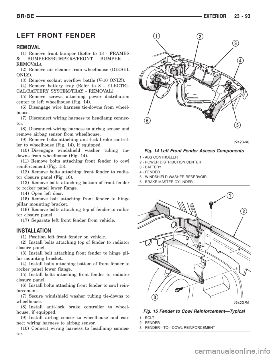
(5) Remove screws attaching power distribution
center to left wheelhouse (Fig. 14).
(6) Disengage wire harness tie-downs from wheel-
house.
(7) Disconnect wiring harness to headlamp connec-
tor.
(8) Disconnect wiring harness to airbag sensor and
remove airbag sensor from wheelhouse.
(9) Remove bolts attaching anti-lock brake control-
ler to wheelhouse (Fig. 14), if equipped.
(10) Disengage windshield washer tubing tie-
downs from wheelhouse (Fig. 14).
(11) Remove bolts attaching front fender to cowl
reinforcement (Fig. 15).
(12) Remove bolts attaching front fender to radia-
tor closure panel (Fig. 16).
(13) Remove bolts attaching bottom of front fender
to rocker panel lower flange.
(14) Open left door.
(15) Remove bolt attaching front fender to hinge
pillar mounting bracket.
(16) Remove bolts attaching top of fender to radia-
tor closure panel.
(17) Separate left front fender from vehicle.
INSTALLATION
(1) Position left front fender on vehicle.
(2) Install bolts attaching top of fender to radiator
closure panel.
(3) Install bolt attaching front fender to hinge pil-
lar mounting bracket.
(4) Install bolts attaching bottom of front fender to
rocker panel lower flange.
(5) Install bolts attaching front fender to radiator
closure panel.
(6) Install bolts attaching front fender to cowl rein-
forcement.
(7) Secure windshield washer tubing tie-downs to
wheelhouse.
(8) Install anti-lock brake controller to wheel-
house, if equipped.
(9) Install airbag sensor to wheelhouse and con-
nect wiring harness to airbag sensor.
(10) Connect wiring harness to headlamp connec-
tor.
Fig. 14 Left Front Fender Access Components
1 - ABS CONTROLLER
2 - POWER DISTRIBUTION CENTER
3 - BATTERY
4 - FENDER
5 - WINDSHIELD WASHER RESERVOIR
6 - BRAKE MASTER CYLINDER
Fig. 15 Fender to Cowl ReinforcementÐTypical
1 - BOLT
2 - FENDER
3 - FENDERÐTOÐCOWL REINFORCEMENT
BR/BEEXTERIOR 23 - 93