DODGE RAM 2002 Service Repair Manual
Manufacturer: DODGE, Model Year: 2002, Model line: RAM, Model: DODGE RAM 2002Pages: 2255, PDF Size: 62.07 MB
Page 2021 of 2255
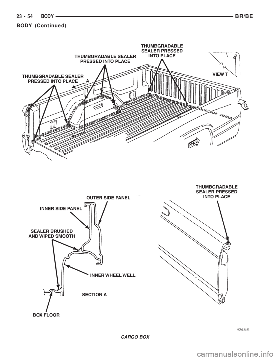
CARGO BOX
23 - 54 BODYBR/BE
BODY (Continued)
Page 2022 of 2255
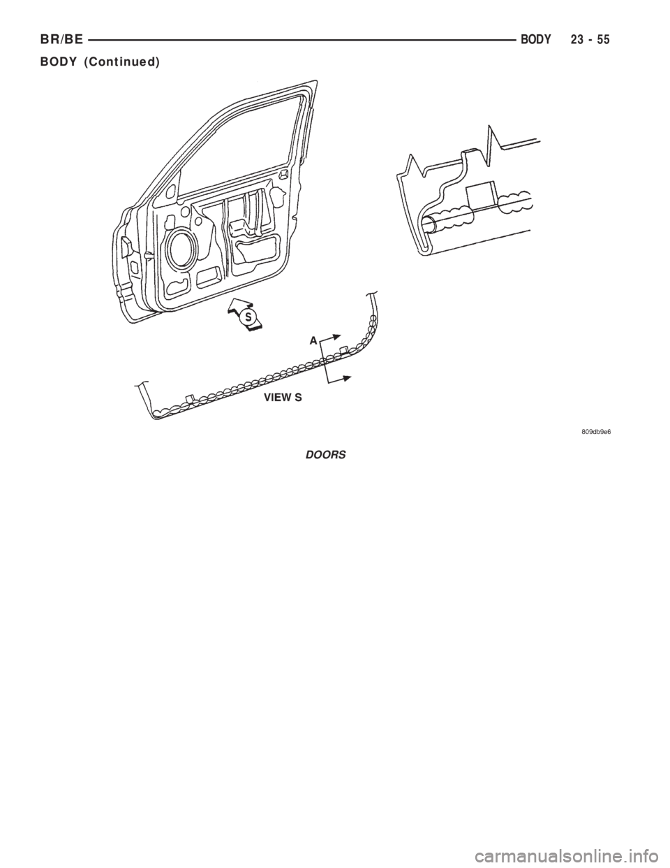
DOORS
BR/BEBODY 23 - 55
BODY (Continued)
Page 2023 of 2255
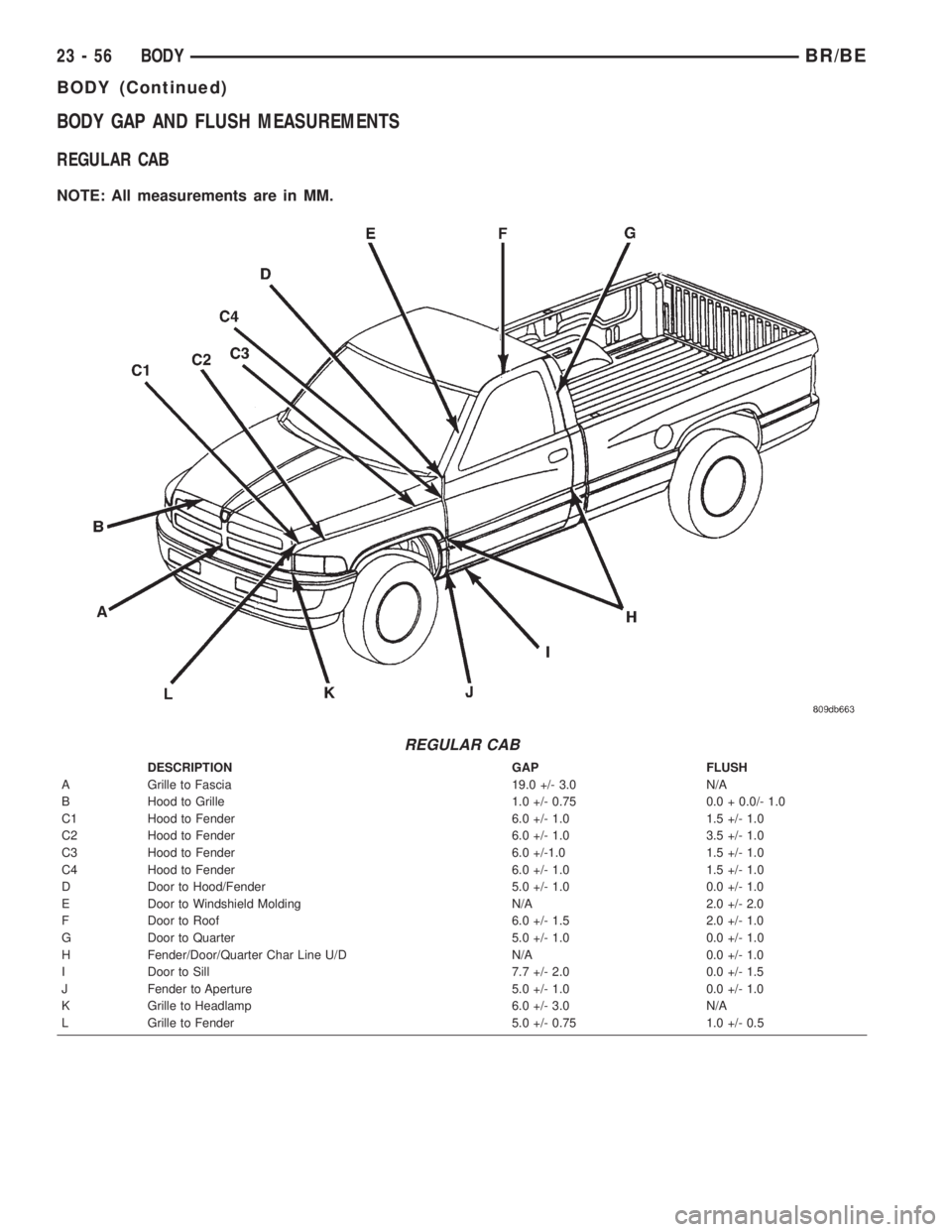
BODY GAP AND FLUSH MEASUREMENTS
REGULAR CAB
NOTE: All measurements are in MM.
REGULAR CAB
DESCRIPTION GAP FLUSH
A Grille to Fascia 19.0 +/- 3.0 N/A
B Hood to Grille 1.0 +/- 0.75 0.0 + 0.0/- 1.0
C1 Hood to Fender 6.0 +/- 1.0 1.5 +/- 1.0
C2 Hood to Fender 6.0 +/- 1.0 3.5 +/- 1.0
C3 Hood to Fender 6.0 +/-1.0 1.5 +/- 1.0
C4 Hood to Fender 6.0 +/- 1.0 1.5 +/- 1.0
D Door to Hood/Fender 5.0 +/- 1.0 0.0 +/- 1.0
E Door to Windshield Molding N/A 2.0 +/- 2.0
F Door to Roof 6.0 +/- 1.5 2.0 +/- 1.0
G Door to Quarter 5.0 +/- 1.0 0.0 +/- 1.0
H Fender/Door/Quarter Char Line U/D N/A 0.0 +/- 1.0
I Door to Sill 7.7 +/- 2.0 0.0 +/- 1.5
J Fender to Aperture 5.0 +/- 1.0 0.0 +/- 1.0
K Grille to Headlamp 6.0 +/- 3.0 N/A
L Grille to Fender 5.0 +/- 0.75 1.0 +/- 0.5
23 - 56 BODYBR/BE
BODY (Continued)
Page 2024 of 2255
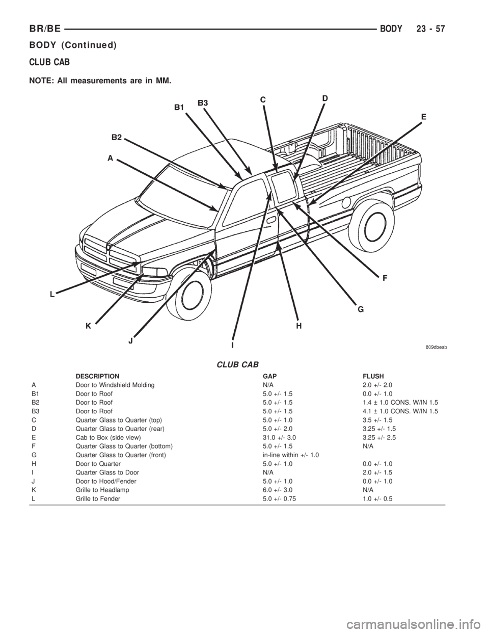
CLUB CAB
NOTE: All measurements are in MM.
CLUB CAB
DESCRIPTION GAP FLUSH
A Door to Windshield Molding N/A 2.0 +/- 2.0
B1 Door to Roof 5.0 +/- 1.5 0.0 +/- 1.0
B2 Door to Roof 5.0 +/- 1.5 1.4 1.0 CONS. W/IN 1.5
B3 Door to Roof 5.0 +/- 1.5 4.1 1.0 CONS. W/IN 1.5
C Quarter Glass to Quarter (top) 5.0 +/- 1.0 3.5 +/- 1.5
D Quarter Glass to Quarter (rear) 5.0 +/- 2.0 3.25 +/- 1.5
E Cab to Box (side view) 31.0 +/- 3.0 3.25 +/- 2.5
F Quarter Glass to Quarter (bottom) 5.0 +/- 1.5 N/A
G Quarter Glass to Quarter (front) in-line within +/- 1.0
H Door to Quarter 5.0 +/- 1.0 0.0 +/- 1.0
I Quarter Glass to Door N/A 2.0 +/- 1.5
J Door to Hood/Fender 5.0 +/- 1.0 0.0 +/- 1.0
K Grille to Headlamp 6.0 +/- 3.0 N/A
L Grille to Fender 5.0 +/- 0.75 1.0 +/- 0.5
BR/BEBODY 23 - 57
BODY (Continued)
Page 2025 of 2255
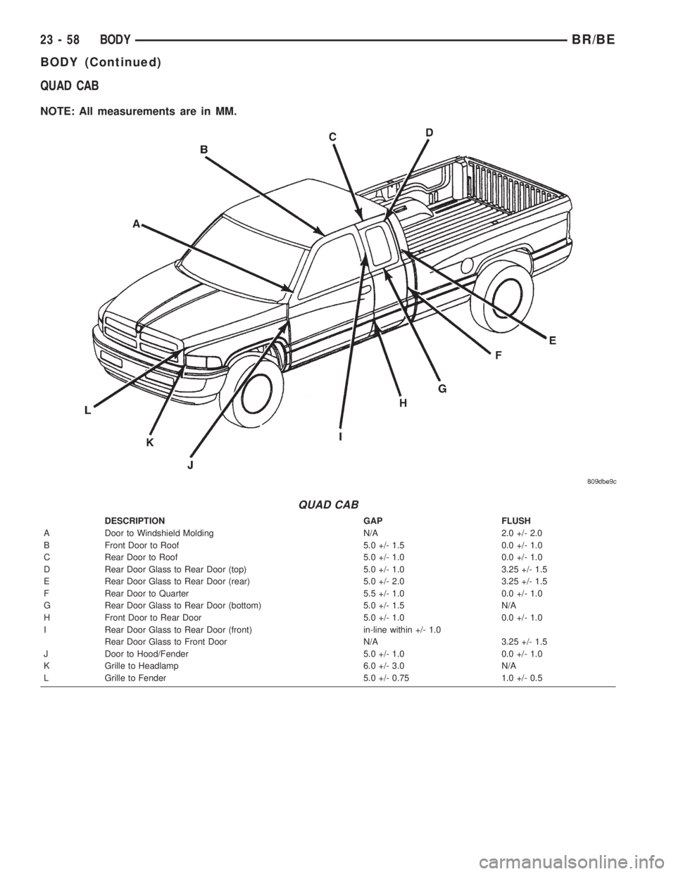
QUAD CAB
NOTE: All measurements are in MM.
QUAD CAB
DESCRIPTION GAP FLUSH
A Door to Windshield Molding N/A 2.0 +/- 2.0
B Front Door to Roof 5.0 +/- 1.5 0.0 +/- 1.0
C Rear Door to Roof 5.0 +/- 1.0 0.0 +/- 1.0
D Rear Door Glass to Rear Door (top) 5.0 +/- 1.0 3.25 +/- 1.5
E Rear Door Glass to Rear Door (rear) 5.0 +/- 2.0 3.25 +/- 1.5
F Rear Door to Quarter 5.5 +/- 1.0 0.0 +/- 1.0
G Rear Door Glass to Rear Door (bottom) 5.0 +/- 1.5 N/A
H Front Door to Rear Door 5.0 +/- 1.0 0.0 +/- 1.0
I Rear Door Glass to Rear Door (front) in-line within +/- 1.0
Rear Door Glass to Front Door N/A 3.25 +/- 1.5
J Door to Hood/Fender 5.0 +/- 1.0 0.0 +/- 1.0
K Grille to Headlamp 6.0 +/- 3.0 N/A
L Grille to Fender 5.0 +/- 0.75 1.0 +/- 0.5
23 - 58 BODYBR/BE
BODY (Continued)
Page 2026 of 2255
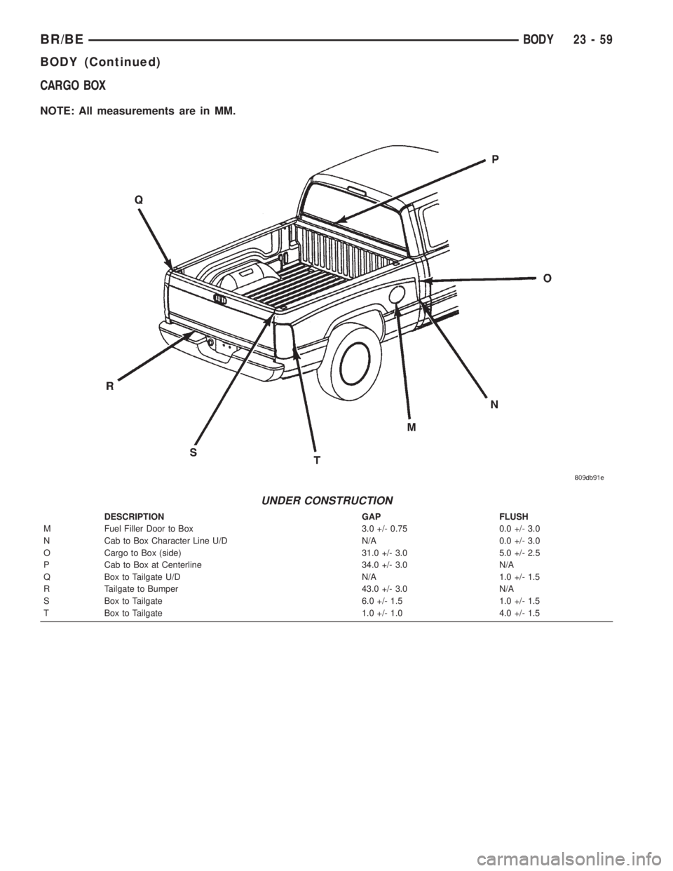
CARGO BOX
NOTE: All measurements are in MM.
UNDER CONSTRUCTION
DESCRIPTION GAP FLUSH
M Fuel Filler Door to Box 3.0 +/- 0.75 0.0 +/- 3.0
N Cab to Box Character Line U/D N/A 0.0 +/- 3.0
O Cargo to Box (side) 31.0 +/- 3.0 5.0 +/- 2.5
P Cab to Box at Centerline 34.0 +/- 3.0 N/A
Q Box to Tailgate U/D N/A 1.0 +/- 1.5
R Tailgate to Bumper 43.0 +/- 3.0 N/A
S Box to Tailgate 6.0 +/- 1.5 1.0 +/- 1.5
T Box to Tailgate 1.0 +/- 1.0 4.0 +/- 1.5
BR/BEBODY 23 - 59
BODY (Continued)
Page 2027 of 2255
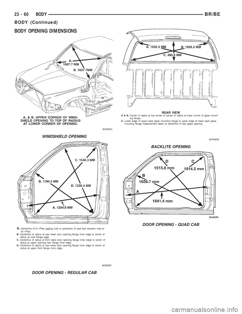
BODY OPENING DIMENSIONS
WINDSHIELD OPENING
DOOR OPENING - REGULAR CAB
BACKLITE OPENING
DOOR OPENING - QUAD CAB
23 - 60 BODYBR/BE
BODY (Continued)
Page 2028 of 2255
TORQUE SPECIFICATIONS
BODY COMPONENTS
Description N´m Ft. lbs. In. lbs.
Ash receiver flame
shield screws2Ð20
Bench seat back latch
bolts25 18 Ð
Bench seat back to
cushion pivot bolt25 18 Ð
Bench seat front anchor
bolt54 40 Ð
Bench seat rear inboard
anchor nut40 30 Ð
Bench seat rear
outboard anchor nut54 40 Ð
Bench seat riser front
bolts54 40 Ð
Bench seat riser rear
inboard nuts40 30 Ð
Bench seat riser rear
outboard nuts54 40 Ð
Bench seat slider bolts 10 Ð 89
Bench seat/front seat
track to frame bolt25 18 Ð
Bench seat/inboard belt
buckle anchor bolt40 30 Ð
Bench seat/rear seat
track to frame bolt25 18 Ð
Cab mounting bolts 81 60 Ð
Cargo box frame bolts 54 40 Ð
Cargo door hinge bolts 28 21 Ð
Cargo door lower latch
nuts28 21 Ð
Cargo door lower striker
screws28 21 Ð
Cargo door upper larch
bolts23 17 Ð
Cargo door upper striker
bolts23 17 Ð
Cargo door vent window
latch to glass screws5Ð44
Center seat armrest
latch cover fastener4Ð35
Center seat armrest/
console bolts20 15 Ð
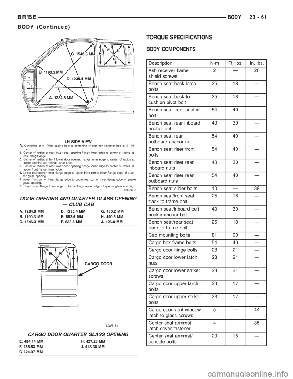
DOOR OPENING AND QUARTER GLASS OPENING
Ð CLUB CAB
A. 1284.8 MM D. 1235.4 MM G. 436.2 MM
B. 1190.3 MM E. 582.6 MM H. 440.5 MM
C. 1546.3 MM F. 538.8 MM J. 426.8 MM
CARGO DOOR QUARTER GLASS OPENING
E. 484.14 MM H. 427.28 MM
F. 456.83 MM J. 418.38 MM
G 424.97 MM
BR/BEBODY 23 - 61
BODY (Continued)
Page 2029 of 2255
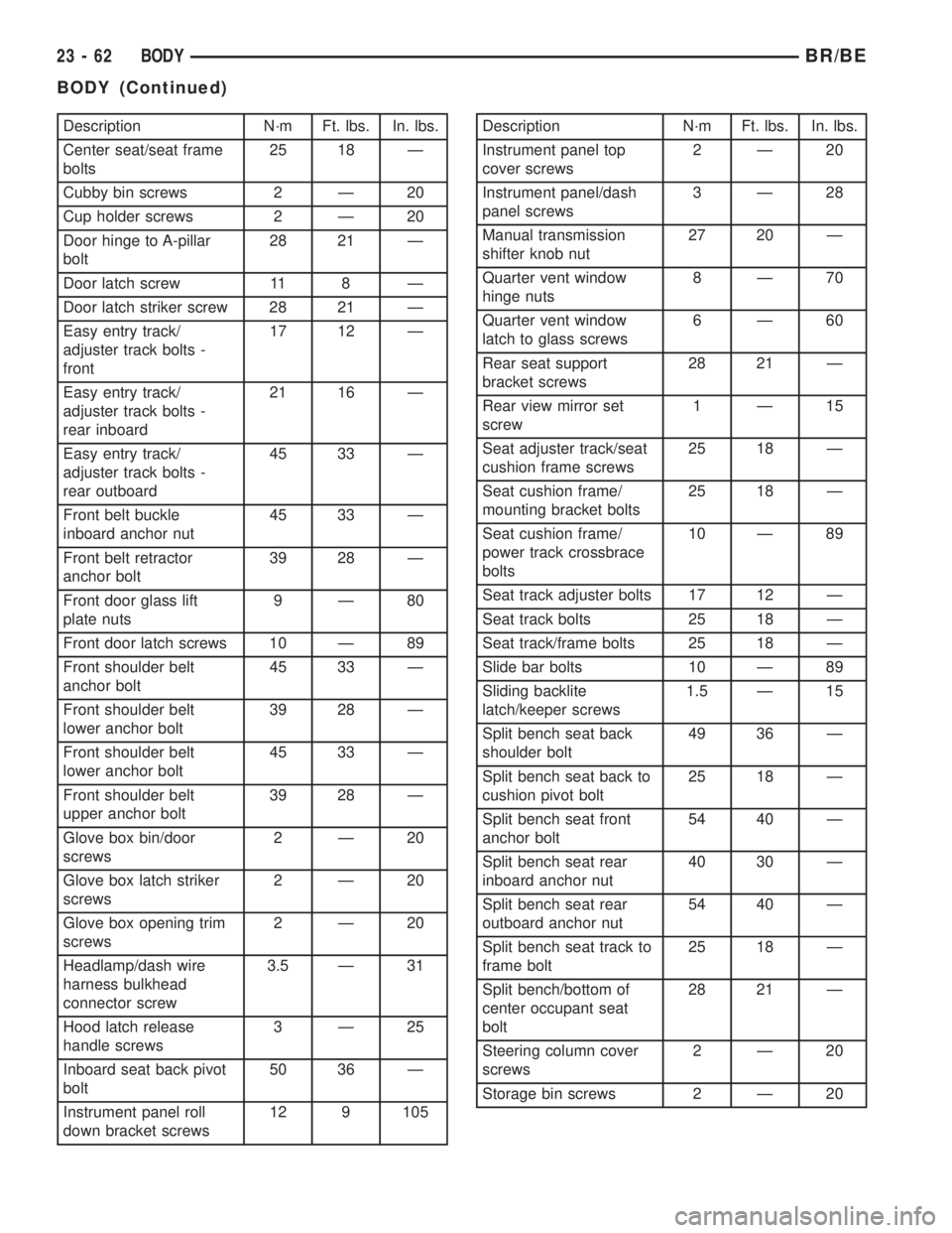
Description N´m Ft. lbs. In. lbs.
Center seat/seat frame
bolts25 18 Ð
Cubby bin screws 2 Ð 20
Cup holder screws 2 Ð 20
Door hinge to A-pillar
bolt28 21 Ð
Door latch screw 11 8 Ð
Door latch striker screw 28 21 Ð
Easy entry track/
adjuster track bolts -
front17 12 Ð
Easy entry track/
adjuster track bolts -
rear inboard21 16 Ð
Easy entry track/
adjuster track bolts -
rear outboard45 33 Ð
Front belt buckle
inboard anchor nut45 33 Ð
Front belt retractor
anchor bolt39 28 Ð
Front door glass lift
plate nuts9Ð80
Front door latch screws 10 Ð 89
Front shoulder belt
anchor bolt45 33 Ð
Front shoulder belt
lower anchor bolt39 28 Ð
Front shoulder belt
lower anchor bolt45 33 Ð
Front shoulder belt
upper anchor bolt39 28 Ð
Glove box bin/door
screws2Ð20
Glove box latch striker
screws2Ð20
Glove box opening trim
screws2Ð20
Headlamp/dash wire
harness bulkhead
connector screw3.5 Ð 31
Hood latch release
handle screws3Ð25
Inboard seat back pivot
bolt50 36 Ð
Instrument panel roll
down bracket screws12 9 105Description N´m Ft. lbs. In. lbs.
Instrument panel top
cover screws2Ð20
Instrument panel/dash
panel screws3Ð28
Manual transmission
shifter knob nut27 20 Ð
Quarter vent window
hinge nuts8Ð70
Quarter vent window
latch to glass screws6Ð60
Rear seat support
bracket screws28 21 Ð
Rear view mirror set
screw1Ð15
Seat adjuster track/seat
cushion frame screws25 18 Ð
Seat cushion frame/
mounting bracket bolts25 18 Ð
Seat cushion frame/
power track crossbrace
bolts10 Ð 89
Seat track adjuster bolts 17 12 Ð
Seat track bolts 25 18 Ð
Seat track/frame bolts 25 18 Ð
Slide bar bolts 10 Ð 89
Sliding backlite
latch/keeper screws1.5 Ð 15
Split bench seat back
shoulder bolt49 36 Ð
Split bench seat back to
cushion pivot bolt25 18 Ð
Split bench seat front
anchor bolt54 40 Ð
Split bench seat rear
inboard anchor nut40 30 Ð
Split bench seat rear
outboard anchor nut54 40 Ð
Split bench seat track to
frame bolt25 18 Ð
Split bench/bottom of
center occupant seat
bolt28 21 Ð
Steering column cover
screws2Ð20
Storage bin screws 2 Ð 20
23 - 62 BODYBR/BE
BODY (Continued)
Page 2030 of 2255
DECKLID/HATCH/LIFTGATE/TAILGATE
TABLE OF CONTENTS
page page
APPLIQUE
REMOVAL.............................63
INSTALLATION.........................63
DECALS
REMOVAL.............................64
INSTALLATION.........................64
HANDLE ESCUTCHEON
REMOVAL.............................64
INSTALLATION.........................64
LATCH
REMOVAL.............................65
INSTALLATION.........................65
LATCH HANDLE
REMOVAL.............................66INSTALLATION.........................66
LATCH STRIKER
REMOVAL.............................66
INSTALLATION.........................66
SLAM BUMPER
REMOVAL.............................67
INSTALLATION.........................67
CHECK CABLE
REMOVAL.............................67
INSTALLATION.........................67
TAILGATE
REMOVAL.............................67
INSTALLATION.........................67
APPLIQUE
REMOVAL
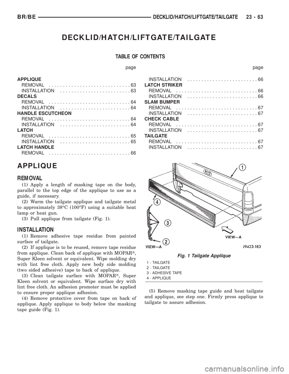
(1) Apply a length of masking tape on the body,
parallel to the top edge of the applique to use as a
guide, if necessary.
(2) Warm the tailgate applique and tailgate metal
to approximately 38ÉC (100ÉF) using a suitable heat
lamp or heat gun.
(3) Pull applique from tailgate (Fig. 1).
INSTALLATION
(1) Remove adhesive tape residue from painted
surface of tailgate.
(2) If applique is to be reused, remove tape residue
from applique. Clean back of applique with MOPARt,
Super Kleen solvent or equivalent. Wipe molding dry
with lint free cloth. Apply new body side molding
(two sided adhesive) tape to back of applique.
(3) Clean tailgate surface with MOPARt, Super
Kleen solvent or equivalent. Wipe surface dry with
lint free cloth. An adhesion promoter must be applied
to ensure proper applique adhesion.
(4) Remove protective cover from tape on back of
applique. Apply applique to body below the masking
tape guide (Fig. 1).(5) Remove masking tape guide and heat tailgate
and applique, see step one. Firmly press applique to
tailgate to assure adhesion.
Fig. 1 Tailgate Applique
1 - TAILGATE
2 - TAILGATE
3 - ADHESIVE TAPE
4 - APPLIQUE
BR/BEDECKLID/HATCH/LIFTGATE/TAILGATE 23 - 63