brake sensor DODGE RAM 2002 Service Owner's Manual
[x] Cancel search | Manufacturer: DODGE, Model Year: 2002, Model line: RAM, Model: DODGE RAM 2002Pages: 2255, PDF Size: 62.07 MB
Page 376 of 2255
DIAGNOSIS AND TESTING - CCD DATA BUS
CCD BUS FAILURE
The CCD data bus can be monitored using the
DRBIIItscan tool. However, it is possible for the
data bus to pass all tests since the voltage parame-
ters will be in ªrangeª and false signals are being
sent. There are essentially 12 ªhard failuresª that
can occur with the CCD data bus:
²Bus Shorted to Battery
²Bus Shorted to 5 Volts
²Bus Shorted to Ground
²Bus (+) Shorted to Bus (±)
²Bus (±) and Bus (+) Open
²Bus (+) Open
²Bus (±) Open
²No Bus Bias
²Bus Bias Level Too High
²Bus Bias Level Too Low
²No Bus Termination
²Not Receiving Bus Messages Correctly
Refer to the appropriate diagnostic information for
details on how to diagnose these faults using a
DRBIIItscan tool.
BUS FAILURE VISUAL SYMPTOM DIAGNOSIS
The following visible symptoms or customer com-
plaints, alone or in combination, may indicate a CCD
data bus failure:
²Airbag Indicator and Malfunction Indicator
Lamp (MIL) Illuminated
²Instrument Cluster Gauges (All) Inoperative
²No Compass Mini-Trip Computer (CMTC) Oper-
ation (if equipped)
CONTROLLER ANTILOCK
BRAKE
DESCRIPTION
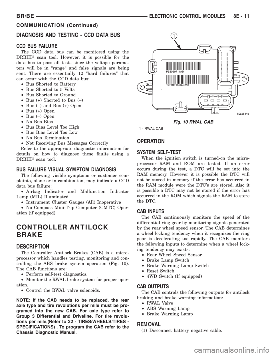
The Controller Antilock Brakes (CAB) is a micro-
processor which handles testing, monitoring and con-
trolling the ABS brake system operation (Fig. 10).
The CAB functions are:
²Perform self-test diagnostics.
²Monitor the RWAL brake system for proper oper-
ation.
²Control the RWAL valve solenoids.
NOTE: If the CAB needs to be replaced, the rear
axle type and tire revolutions per mile must be pro-
gramed into the new CAB. For axle type refer to
Group 3 Differential and Driveline. For tire revolu-
tions per mile,(Refer to 22 - TIRES/WHEELS/TIRES -
SPECIFICATIONS) . To program the CAB refer to the
Chassis Diagnostic Manual.
OPERATION
SYSTEM SELF-TEST
When the ignition switch is turned-on the micro-
processor RAM and ROM are tested. If an error
occurs during the test, a DTC will be set into the
RAM memory. However it is possible the DTC will
not be stored in memory if the error has occurred in
the RAM module were the DTC's are stored. Also it
is possible a DTC may not be stored if the error has
occurred in the ROM which signals the RAM to store
the DTC.
CAB INPUTS
The CAB continuously monitors the speed of the
differential ring gear by monitoring signals generated
by the rear wheel speed sensor. The CAB determines
a wheel locking tendency when it recognizes the ring
gear is decelerating too rapidly. The CAB monitors
the following inputs to determine when a wheel lock-
ing tendency may exists:
²Rear Wheel Speed Sensor
²Brake Lamp Switch
²Brake Warning Lamp Switch
²Reset Switch
²4WD Switch (If equipped)
CAB OUTPUTS
The CAB controls the following outputs for antilock
braking and brake warning information:
²RWAL Valve
²ABS Warning Lamp
²Brake Warning Lamp
REMOVAL
(1) Disconnect battery negative cable.
Fig. 10 RWAL CAB
1-RWALCAB
BR/BEELECTRONIC CONTROL MODULES 8E - 11
COMMUNICATION (Continued)
Page 383 of 2255
OPERATION
OPERATION - PCM - GAS ENGINES
The PCM operates the fuel system. The PCM is a
pre-programmed, triple microprocessor digital com-
puter. It regulates ignition timing, air-fuel ratio,
emission control devices, charging system, certain
transmission features, speed control, air conditioning
compressor clutch engagement and idle speed. The
PCM can adapt its programming to meet changing
operating conditions.
The PCM receives input signals from various
switches and sensors. Based on these inputs, the
PCM regulates various engine and vehicle operations
through different system components. These compo-
nents are referred to as Powertrain Control Module
(PCM) Outputs. The sensors and switches that pro-
vide inputs to the PCM are considered Powertrain
Control Module (PCM) Inputs.
The PCM adjusts ignition timing based upon
inputs it receives from sensors that react to: engine
rpm, manifold absolute pressure, engine coolant tem-
perature, throttle position, transmission gear selec-
tion (automatic transmission), vehicle speed and the
brake switch.
The PCM adjusts idle speed based on inputs it
receives from sensors that react to: throttle position,
vehicle speed, transmission gear selection, engine
coolant temperature and from inputs it receives from
the air conditioning clutch switch and brake switch.
Based on inputs that it receives, the PCM adjusts
ignition coil dwell. The PCM also adjusts the gener-
ator charge rate through control of the generator
field and provides speed control operation.
NOTE: PCM Inputs:
²A/C request (if equipped with factory A/C)
²A/C select (if equipped with factory A/C)
²Auto shutdown (ASD) sense
²Battery temperature
²Battery voltage
²Brake switch
²CCD bus (+) circuits
²CCD bus (-) circuits
²Camshaft position sensor signal
²Crankshaft position sensor
²Data link connection for DRB scan tool
²Engine coolant temperature sensor
²Fuel level
²Generator (battery voltage) output
²Ignition circuit sense (ignition switch in on/off/
crank/run position)
²Intake manifold air temperature sensor
²Leak detection pump (switch) sense (if equipped)
²Manifold absolute pressure (MAP) sensor²Oil pressure
²Output shaft speed sensor
²Overdrive/override switch
²Oxygen sensors
²Park/neutral switch (auto. trans. only)
²Power ground
²Sensor return
²Signal ground
²Speed control multiplexed single wire input
²Throttle position sensor
²Transmission governor pressure sensor
²Transmission temperature sensor
²Vehicle speed inputs from ABS or RWAL system
NOTE: PCM Outputs:
²A/C clutch relay
²Auto shutdown (ASD) relay
²CCD bus (+/-) circuits for: speedometer, voltme-
ter, fuel gauge, oil pressure gauge/lamp, engine temp.
gauge and speed control warn. lamp
²Data link connection for DRB scan tool
²EGR valve control solenoid (if equipped)
²EVAP canister purge solenoid
²Five volt sensor supply (primary)
²Five volt sensor supply (secondary)
²Fuel injectors
²Fuel pump relay
²Generator field driver (-)
²Generator field driver (+)
²Generator lamp (if equipped)
²Idle air control (IAC) motor
²Ignition coil
²Leak detection pump (if equipped)
²Malfunction indicator lamp (Check engine lamp).
Driven through CCD circuits.
²Overdrive indicator lamp (if equipped)
²Service Reminder Indicator (SRI) Lamp (MAINT
REQ'D lamp). Driven through CCD circuits.
²Speed control vacuum solenoid
²Speed control vent solenoid
²Tachometer (if equipped). Driven through CCD
circuits.
²Transmission convertor clutch circuit
²Transmission 3±4 shift solenoid
²Transmission relay
²Transmission temperature lamp (if equipped)
²Transmission variable force solenoid
OPERATION - DIESEL
Two different control modules are used: The Pow-
ertrain Control Module (PCM), and the Engine Con-
trol Module (ECM). The ECMcontrolsthe fuel
system. The PCMdoes not controlthe fuel system.
The PCM's main function is to control: the vehicle
charging system, speed control system, transmission,
air conditioning system and certain bussed messages.
8E - 18 ELECTRONIC CONTROL MODULESBR/BE
POWERTRAIN CONTROL MODULE (Continued)
Page 384 of 2255
The PCM can adapt its programming to meet
changing operating conditions.
The PCM receives input signals from various
switches and sensors. Based on these inputs, the
PCM regulates various engine and vehicle operations
through different system components. These compo-
nents are referred to asPCM Outputs.The sensors
and switches that provide inputs to the PCM are con-
sideredPCM Inputs.
NOTE: PCM Inputs:
²A/C request (if equipped with factory A/C)
²A/C select (if equipped with factory A/C)
²Accelerator Pedal Position Sensor (APPS) output
from ECM
²Auto shutdown (ASD) relay sense
²Battery temperature sensor
²Battery voltage
²Brake switch
²CCD bus (+) circuits
²CCD bus (-) circuits
²Crankshaft Position Sensor (CKP) output from
ECM
²Data link connection for DRB scan tool
²Fuel level sensor
²Generator (battery voltage) output
²Ignition sense
²Output shaft speed sensor
²Overdrive/override switch
²Park/neutral switch (auto. trans. only)
²Power ground
²Sensor return
²Signal ground
²Speed control resume switch
²Speed control set switch
²Speed control on/off switch
²Transmission governor pressure sensor
²Transmission temperature sensor
²Vehicle speed inputs from ABS or RWAL system
NOTE: PCM Outputs:
After inputs are received by the PCM, certain sen-
sors, switches and components are controlled or reg-
ulated by the PCM. These are consideredPCM
Outputs.These outputs are for:
²A/C clutch relay and A/C clutch
²Auto shutdown (ASD) relay
²CCD bus (+/-) circuits for: speedometer, voltme-
ter, fuel gauge, oil pressure gauge/lamp, engine temp.
gauge and speed control warn. lamp
²Data link connection for DRB scan tool
²Five volt sensor supply
²Generator field driver (-)
²Generator field driver (+)
²Generator lamp (if equipped)²Malfunction indicator lamp (Check engine lamp)
²Overdrive warning lamp (if equipped)
²Speed control vacuum solenoid
²Speed control vent solenoid
²Tachometer (if equipped)
²Transmission convertor clutch circuit
²Transmission 3±4 shift solenoid
²Transmission relay
²Transmission temperature lamp (if equipped)
²Transmission variable force solenoid (governor
sol.)
OPERATION - 5 VOLT SUPPLIES
Primary 5±volt supply:
²supplies the required 5 volt power source to the
Crankshaft Position (CKP) sensor.
²supplies the required 5 volt power source to the
Camshaft Position (CMP) sensor.
²supplies a reference voltage for the Manifold
Absolute Pressure (MAP) sensor.
²supplies a reference voltage for the Throttle
Position Sensor (TPS) sensor.
Secondary 5±volt supply:
²supplies the required 5 volt power source to the
oil pressure sensor.
²supplies the required 5 volt power source for the
Vehicle Speed Sensor (VSS) (if equipped).
²supplies the 5 volt power source to the transmis-
sion pressure sensor (if equipped with an RE auto-
matic transmission).
OPERATION - IGNITION CIRCUIT SENSE
The ignition circuit sense input tells the PCM the
ignition switch has energized the ignition circuit.
Battery voltage is also supplied to the PCM
through the ignition switch when the ignition is in
the RUN or START position. This is referred to as
the9ignition sense9circuit and is used to9wake up9
the PCM. Voltage on the ignition input can be as low
as 6 volts and the PCM will still function. Voltage is
supplied to this circuit to power the PCM's 8-volt reg-
ulator and to allow the PCM to perform fuel, ignition
and emissions control functions.
REMOVAL
USE THE DRB SCAN TOOL TO REPROGRAM
THE NEW POWERTRAIN CONTROL MODULE
(PCM) WITH THE VEHICLES ORIGINAL IDEN-
TIFICATION NUMBER (VIN) AND THE VEHI-
CLES ORIGINAL MILEAGE. IF THIS STEP IS
NOT DONE, A DIAGNOSTIC TROUBLE CODE
(DTC) MAY BE SET.
The PCM is located in the engine compartment
(Fig. 18).
BR/BEELECTRONIC CONTROL MODULES 8E - 19
POWERTRAIN CONTROL MODULE (Continued)
Page 409 of 2255
VOLTAGE DROP TEST
WARNING: MODELS EQUIPPED WITH THE DIESEL
ENGINE OPTION ALSO HAVE AN AUTOMATIC
SHUTDOWN (ASD) RELAY LOCATED IN THE
POWER DISTRIBUTION CENTER (PDC), IN THE
ENGINE COMPARTMENT. HOWEVER, REMOVAL OF
THE ASD RELAY MAY NOT PREVENT THE DIESEL
ENGINE FROM STARTING. BE CERTAIN TO ALSO
DISCONNECT THE FUEL SHUTDOWN SOLENOID
WIRE HARNESS CONNECTOR ON MODELS WITH A
DIESEL ENGINE. FAILURE TO DO SO MAY RESULT
IN PERSONAL INJURY.
The following operation will require a voltmeter
accurate to 1/10 (0.10) volt. Before performing this
test, be certain that the following procedures are
accomplished:
²The battery is fully-charged and load tested
(Refer to 8 - ELECTRICAL/BATTERY SYSTEM/BAT-
TERY - STANDARD PROCEDURE).
²Fully engage the parking brake.
²If the vehicle is equipped with an automatic
transmission, place the gearshift selector lever in the
Park position. If the vehicle is equipped with a man-
ual transmission, place the gearshift selector lever in
the Neutral position and block the clutch pedal in the
fully depressed position.
²Verify that all lamps and accessories are turned
off.
²To prevent a gasoline engine from starting,
remove the Automatic ShutDown (ASD) relay. The
ASD relay is located in the Power Distribution Cen-
ter (PDC), in the engine compartment. See the fuse
and relay layout label affixed to the underside of the
PDC cover for ASD relay identification and location.
To prevent a diesel engine from starting, disconnect
the fuel shutdown solenoid wire harness connector
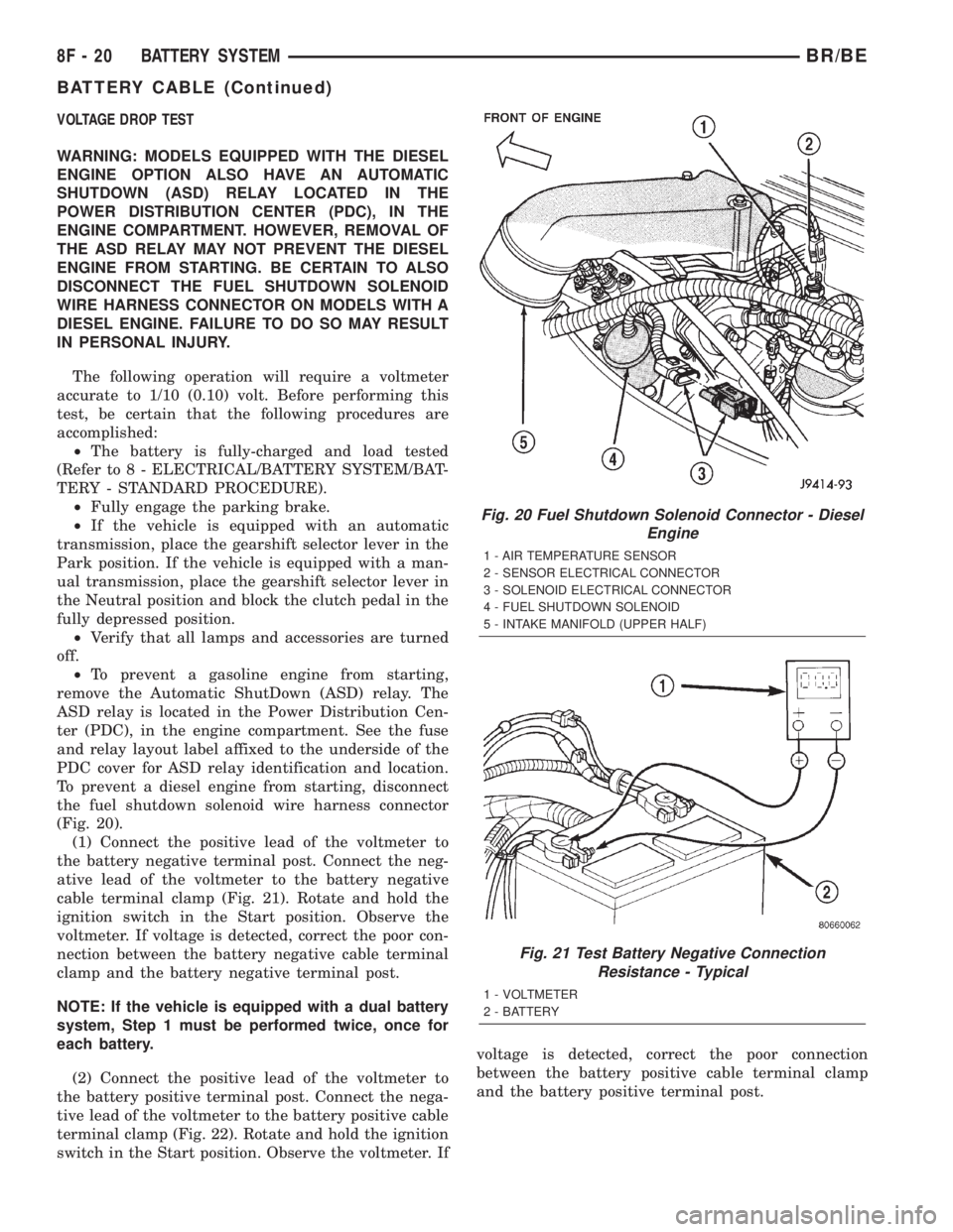
(Fig. 20).
(1) Connect the positive lead of the voltmeter to
the battery negative terminal post. Connect the neg-
ative lead of the voltmeter to the battery negative
cable terminal clamp (Fig. 21). Rotate and hold the
ignition switch in the Start position. Observe the
voltmeter. If voltage is detected, correct the poor con-
nection between the battery negative cable terminal
clamp and the battery negative terminal post.
NOTE: If the vehicle is equipped with a dual battery
system, Step 1 must be performed twice, once for
each battery.
(2) Connect the positive lead of the voltmeter to
the battery positive terminal post. Connect the nega-
tive lead of the voltmeter to the battery positive cable
terminal clamp (Fig. 22). Rotate and hold the ignition
switch in the Start position. Observe the voltmeter. Ifvoltage is detected, correct the poor connection
between the battery positive cable terminal clamp
and the battery positive terminal post.
Fig. 20 Fuel Shutdown Solenoid Connector - Diesel
Engine
1 - AIR TEMPERATURE SENSOR
2 - SENSOR ELECTRICAL CONNECTOR
3 - SOLENOID ELECTRICAL CONNECTOR
4 - FUEL SHUTDOWN SOLENOID
5 - INTAKE MANIFOLD (UPPER HALF)
Fig. 21 Test Battery Negative Connection
Resistance - Typical
1 - VOLTMETER
2 - BATTERY
8F - 20 BATTERY SYSTEMBR/BE
BATTERY CABLE (Continued)
Page 493 of 2255
(Refer to 19 - STEERING/COLUMN - INSTALLA-
TION).
(8) Reconnect the battery negative cable.
NOTE: Some of the indicators in this instrument
cluster are either programmable (upshift indicator)
or automatically configured (cruise, overdrive-off,
and transmission overtemp indicators) when the
cluster is connected to the vehicle electrical sys-
tem. This feature allows those indicator lamps to be
enabled or disabled for compatibility with certain
optional equipment. If a new instrument cluster is
being installed, use a DRBIIITscan tool to program
the instrument cluster with the proper vehicle
equipment option setting to enable and/or disable
the upshift indicator lamp. Refer to the appropriate
diagnostic information.
ABS INDICATOR
DESCRIPTION
An Antilock Brake System (ABS) indicator is stan-
dard equipment on all instrument clusters. This indi-
cator serves both the standard equipment Rear
Wheel Anti-Lock (RWAL) and optional equipment
4-Wheel Anti-Lock (4WAL) brake systems. The ABS
indicator is located near the lower edge of the instru-
ment cluster overlay, to the left of center. The ABS
indicator consists of a stencilled cutout of the Inter-
national Control and Display Symbol icon for ªFail-
ure of Anti-lock Braking Systemº in the opaque layer
of the instrument cluster overlay. The dark outer
layer of the overlay prevents the indicator from being
clearly visible when it is not illuminated. An amber
lens behind the cutout in the opaque layer of the
overlay causes the icon to appear in amber through
the translucent outer layer of the overlay when it is
illuminated from behind by a Light Emitting Diode
(LED) soldered onto the instrument cluster electronic
circuit board. The ABS indicator is serviced as a unit
with the instrument cluster.
OPERATION
The ABS indicator gives an indication to the vehi-
cle operator when the ABS system is faulty or inop-
erative. This indicator is controlled by a transistor on
the instrument cluster circuit board based upon clus-
ter programming and electronic messages received by
the cluster from the Controller Antilock Brake (CAB)
over the Chrysler Collision Detection (CCD) data bus.
The ABS indicator Light Emitting Diode (LED)
receives battery current on the instrument cluster
electronic circuit board through the fused ignition
switch output (st-run) circuit whenever the ignition
switch is in the On or Start positions; therefore, theLED will always be off when the ignition switch is in
any position except On or Start. The LED only illu-
minates when it is provided a path to ground by the
instrument cluster transistor. The instrument cluster
will turn on the ABS indicator for the following rea-
sons:
²Bulb Test- Each time the ignition switch is
turned to the On position the ABS indicator is illu-
minated by the cluster for about two seconds as a
bulb test.
²ABS Lamp-On Message- Each time the clus-
ter receives a lamp-on message from the CAB, the
ABS indicator will be illuminated. The indicator
remains illuminated until the cluster receives a
lamp-off message from the CAB, or until the ignition
switch is turned to the Off position, whichever occurs
first.
²Communication Error- If the cluster receives
no lamp-on or lamp-off messages from the CAB for
six consecutive seconds, the ABS indicator is illumi-
nated. The indicator remains illuminated until the
cluster receives a valid message from the CAB, or
until the ignition switch is turned to the Off position,
whichever occurs first.
²Actuator Test- Each time the instrument clus-
ter is put through the actuator test, the ABS indica-
tor will be turned on during the bulb check portion of
the test to confirm the functionality of the LED and
the cluster control circuitry.
²ABS Diagnostic Test- The ABS indicator is
blinked on and off by lamp-on and lamp-off messages
from the CAB during the performance of the ABS
diagnostic tests.
The CAB continually monitors the ABS circuits
and sensors to decide whether the system is in good
operating condition. The CAB then sends the proper
lamp-on or lamp-off messages to the instrument clus-
ter. If the CAB sends a lamp-on message after the
bulb test, it indicates that the CAB has detected a
system malfunction and/or that the ABS system has
become inoperative. The CAB will store a Diagnostic
Trouble Code (DTC) for any malfunction it detects.
Each time the ABS indicator fails to light due to an
open or short in the cluster ABS indicator circuit, the
cluster sends a message notifying the CAB of the
condition, and the CAB will store a DTC. For proper
diagnosis of the antilock brake system, the CAB, the
CCD data bus, or the message inputs to the instru-
ment cluster that control the ABS indicator, a
DRBIIItscan tool is required. Refer to the appropri-
ate diagnostic information.
8J - 14 INSTRUMENT CLUSTERBR/BE
INSTRUMENT CLUSTER (Continued)
Page 494 of 2255
AIRBAG INDICATOR
DESCRIPTION
An airbag indicator is standard equipment on all
instrument clusters. However, on vehicles not
equipped with airbags, this indicator is electronically
disabled. The airbag indicator is located near the
lower edge of the instrument cluster overlay, to the
right of center. The airbag indicator consists of a
stenciled cutout of the word ªAIRBAGº in the opaque
layer of the instrument cluster overlay. The dark
outer layer of the overlay prevents the indicator from
being clearly visible when it is not illuminated. A red
lens behind the cutout in the opaque layer of the
overlay causes the ªAIRBAGº text to appear in red
through the translucent outer layer of the overlay
when it is illuminated from behind by a Light Emit-
ting Diode (LED) soldered onto the instrument clus-
ter electronic circuit board. The airbag indicator is
serviced as a unit with the instrument cluster.
OPERATION
The airbag indicator gives an indication to the
vehicle operator when the airbag system is faulty or
inoperative. The airbag indicator is controlled by a
transistor on the instrument cluster circuit board
based upon cluster programming and electronic mes-
sages received by the cluster from the Airbag Control
Module (ACM) over the Chrysler Collision Detection
(CCD) data bus. The airbag indicator Light Emitting
Diode (LED) receives battery current on the instru-
ment cluster electronic circuit board through the
fused ignition switch output (st-run) circuit whenever
the ignition switch is in the On or Start positions;
therefore, the indicator will always be off when the
ignition switch is in any position except On or Start.
The LED only illuminates when it is provided a path
to ground by the instrument cluster transistor. The
instrument cluster will turn on the airbag indicator
for the following reasons:
²Bulb Test- Each time the ignition switch is
turned to the On position the airbag indicator is illu-
minated for about seven seconds. The first two sec-
onds is the cluster bulb test function, and the
remainder is the ACM bulb test function.
²ACM Lamp-On Message- Each time the clus-
ter receives a lamp-on message from the ACM, the
airbag indicator will be illuminated. The indicator
remains illuminated for about twelve seconds or until
the cluster receives a lamp-off message from the
ACM, whichever is longer.
²Communication Error- If the cluster receives
no airbag messages for three consecutive seconds, the
airbag indicator is illuminated. The indicator
remains illuminated for about twelve seconds or untilthe cluster receives a single lamp-off message from
the ACM, whichever is longer.
²Actuator Test- Each time the cluster is put
through the actuator test, the airbag indicator will be
turned on during the bulb check portion of the test to
confirm the functionality of the LED and the cluster
control circuitry.
The ACM continually monitors the airbag system
circuits and sensors to decide whether the system is
in good operating condition. The ACM then sends the
proper lamp-on or lamp-off messages to the instru-
ment cluster. If the ACM sends a lamp-on message
after the bulb test, it indicates that the ACM has
detected a system malfunction and/or that the air-
bags may not deploy when required, or may deploy
when not required. The ACM will store a Diagnostic
Trouble Code (DTC) for any malfunction it detects.
Each time the airbag indicator fails to illuminate due
to an open or short in the cluster airbag indicator cir-
cuit, the cluster sends a message notifying the ACM
of the condition, the ACM will store a DTC, and the
cluster begins blinking the seat belt indicator. (Refer
to 8 - ELECTRICAL/INSTRUMENT CLUSTER/
SEATBELT INDICATOR - OPERATION). For proper
diagnosis of the airbag system, the ACM, the CCD
data bus, or the message inputs to the instrument
cluster that control the airbag indicator, a DRBIIIt
scan tool is required. Refer to the appropriate diag-
nostic information.
BRAKE/PARK BRAKE
INDICATOR
DESCRIPTION
A brake indicator is standard equipment on all
instrument clusters. The brake indicator is located
near the lower edge of the instrument cluster overlay,
to the right of center. The brake indicator consists of
a stenciled cutout of the word ªBRAKEº in the
opaque layer of the instrument cluster overlay. The
dark outer layer of the overlay prevents the indicator
from being clearly visible when it is not illuminated.
A red lens behind the cutout in the opaque layer of
the overlay causes the ªBRAKEº text to appear in
red through the translucent outer layer of the over-
lay when it is illuminated from behind by a Light
Emitting Diode (LED) soldered onto the instrument
cluster electronic circuit board. The brake indicator is
serviced as a unit with the instrument cluster.
OPERATION
The brake indicator gives an indication to the vehi-
cle operator when the parking brake is applied, or
when there are certain brake hydraulic system mal-
functions. This indicator is controlled by a transistor
BR/BEINSTRUMENT CLUSTER 8J - 15
Page 519 of 2255
(9) Disconnect the instrument panel wire harness
connector for the multi-function switch from the
switch connector receptacle. Check for continuity
between the hazard flasher signal circuit cavities in
the JB receptacle for the combination flasher and the
instrument panel wire harness connector for the
multi-function switch. There should be continuity. If
OK, go to Step 10. If not OK, repair the open hazard
flasher signal circuit between the JB and the multi-
function switch as required.
(10) Check for continuity between the flasher out-
put circuit cavities of the JB receptacle for the com-
bination flasher and in the instrument panel wire
harness connector for the multi-function switch.
There should be continuity. If OK, test the multi-
function switch. (Refer to 8 - ELECTRICAL/LAMPS/
LIGHTING - EXTERIOR/MULTI-FUNCTION
SWITCH - DIAGNOSIS AND TESTING). If not OK,
repair the open flasher output circuit between the JB
and the multi-function switch as required.
SPECIFICATIONS
EXTERIOR LAMPS
LAMP BULB
Back-up 3157
Cargo 921
Center High Mounted
Stop921
Clearance Roof Mounted 168
Fog Lamps 896
Headlamp - SLT 9004LL
Headlamp - Sport Low
Beam9007
Headlamp - Sport High
Beam9004LL
License Plate w/o
Bumper1155
License Plate -Step
Bumper168
Park/Turn Signal 3157NA
Snow Plow Control 161
Tail/Brake/Turn Signal 3157
Tail/Brake/Cab - Chassis 1157
Underhood 105
SPECIAL TOOLS
HEADLAMP ALIGNMENT
BRAKE LAMP SWITCH
DESCRIPTION
The plunger type brake lamp switch is mounted on
a bracket attached to the brake pedal support under
the instrument panel.
CAUTION: The switch can only be adjusted during
initial installation. If the switch is not adjusted prop-
erly a new switch must be installed.
OPERATION
The brake lamp switch is used for the brake lamp,
speed control brake sensor circuits and electronic
brake distribution (EBD). The brake lamp circuit is
open until the plunger is depressed. The speed con-
trol and brake sensor circuits are closed until the
plunger is depressed.
When the brake light switch is activated, the Pow-
ertrain Control Module (PCM) receives an input indi-
cating that the brakes are being applied. After
receiving this input, the PCM maintains idle speed to
a scheduled rpm through control of the Idle Air Con-
trol (IAC) motor. The brake switch input is also used
to disable vent and vacuum solenoid output signals
to the speed control servo.
Vehicles equipped with the speed control option use
a dual function brake lamp switch. The PCM moni-
tors the state of the dual function brake lamp switch.
Refer to the Brake section for more information on
brake lamp switch service and adjustment proce-
dures.
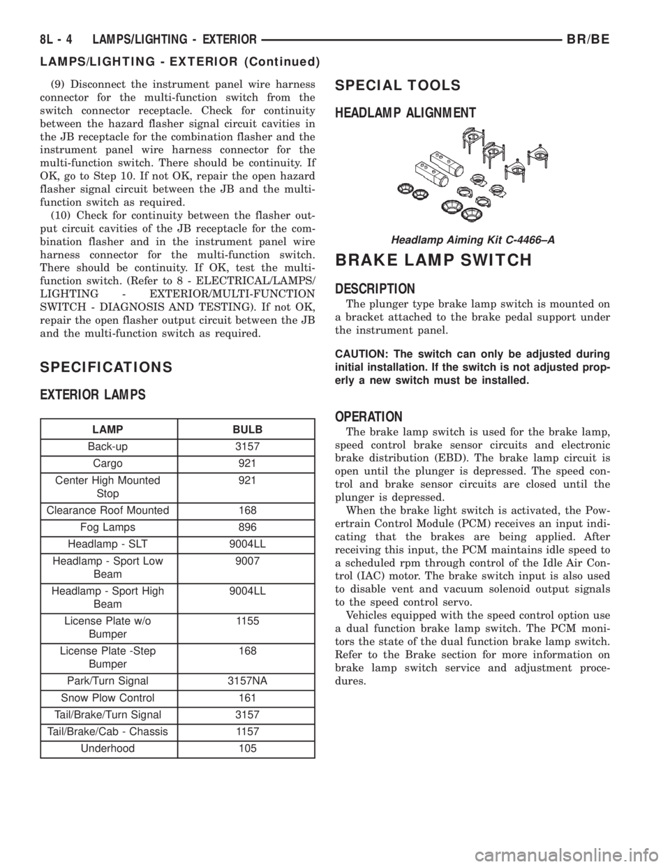
Headlamp Aiming Kit C-4466±A
8L - 4 LAMPS/LIGHTING - EXTERIORBR/BE
LAMPS/LIGHTING - EXTERIOR (Continued)
Page 579 of 2255
OPERATION
The ambient photocell sensor is located on the for-
ward-facing (windshield side) of the rear view mirror
housing, and detects the ambient light levels outside
of the vehicle. The headlamp photocell sensor is
located inside the rear view mirror housing behind
the mirror glass and faces rearward, to detect the
level of the light being received at the rear window
side of the mirror. When the circuitry of the auto-
matic day/night mirror detects that the difference
between the two light levels is too great (the light
level received at the rear of the mirror is much
higher than that at the front of the mirror), it begins
to darken the mirror.
The automatic day/night mirror circuitry also mon-
itors the transmission using an input from the
backup lamp circuit. The mirror circuitry is pro-
grammed to automatically disable its self-dimming
feature whenever it senses that the transmission
backup lamp circuit is energized.
The automatic day/night mirror is a completely
self-contained unit and cannot be repaired. If faulty
or damaged, the entire mirror assembly must be
replaced.
DIAGNOSIS AND TESTING - AUTOMATIC
DAY/NIGHT MIRROR
For circuit descriptions and diagrams, refer to the
appropriate wiring information. The wiring informa-
tion includes wiring diagrams, proper wire and con-
nector repair procedures, details of wire harness
routing and retention, connector pin-out information
and location views for the various wire harness con-
nectors, splices and grounds.
(1) Check the fuse in the junction block. If OK, go
to Step 2. If not OK, repair the shorted circuit or
component as required replace the faulty fuse.
(2) Turn the ignition switch to the On position.
Check for battery voltage at the fuse in the junction
block. If OK, go to Step 3. If not OK, repair the open
circuit to the ignition switch as required.
(3) Turn the ignition switch to the Off position.
Disconnect and isolate the battery negative cable.
Unplug the wire harness connector from the auto-
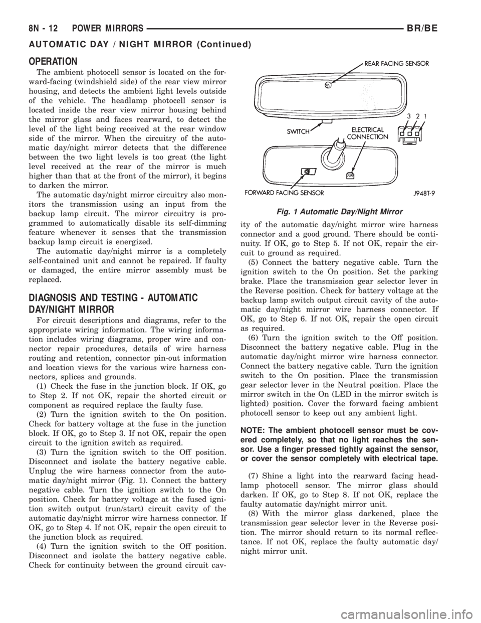
matic day/night mirror (Fig. 1). Connect the battery
negative cable. Turn the ignition switch to the On
position. Check for battery voltage at the fused igni-
tion switch output (run/start) circuit cavity of the
automatic day/night mirror wire harness connector. If
OK, go to Step 4. If not OK, repair the open circuit to
the junction block as required.
(4) Turn the ignition switch to the Off position.
Disconnect and isolate the battery negative cable.
Check for continuity between the ground circuit cav-ity of the automatic day/night mirror wire harness
connector and a good ground. There should be conti-
nuity. If OK, go to Step 5. If not OK, repair the cir-
cuit to ground as required.
(5) Connect the battery negative cable. Turn the
ignition switch to the On position. Set the parking
brake. Place the transmission gear selector lever in
the Reverse position. Check for battery voltage at the
backup lamp switch output circuit cavity of the auto-
matic day/night mirror wire harness connector. If
OK, go to Step 6. If not OK, repair the open circuit
as required.
(6) Turn the ignition switch to the Off position.
Disconnect the battery negative cable. Plug in the
automatic day/night mirror wire harness connector.
Connect the battery negative cable. Turn the ignition
switch to the On position. Place the transmission
gear selector lever in the Neutral position. Place the
mirror switch in the On (LED in the mirror switch is
lighted) position. Cover the forward facing ambient
photocell sensor to keep out any ambient light.
NOTE: The ambient photocell sensor must be cov-
ered completely, so that no light reaches the sen-
sor. Use a finger pressed tightly against the sensor,
or cover the sensor completely with electrical tape.
(7) Shine a light into the rearward facing head-
lamp photocell sensor. The mirror glass should
darken. If OK, go to Step 8. If not OK, replace the
faulty automatic day/night mirror unit.
(8) With the mirror glass darkened, place the
transmission gear selector lever in the Reverse posi-
tion. The mirror should return to its normal reflec-
tance. If not OK, replace the faulty automatic day/
night mirror unit.
Fig. 1 Automatic Day/Night Mirror
8N - 12 POWER MIRRORSBR/BE
AUTOMATIC DAY / NIGHT MIRROR (Continued)
Page 625 of 2255
DESCRIPTION - VEHICLE SPEED INPUT
Gas Engines and/or Diesel With Automatic Trans.
The Vehicle Speed Sensor (VSS) is no longer used
for any Dodge Truck.
Vehicle speed and distance covered are measured
by the Rear Wheel Speed Sensor. The sensor is
mounted to the rear axle. A signal is sent from this
sensor to the Controller Antilock Brake (CAB) com-
puter. A signal is then sent from the CAB to the Pow-
ertrain Control Module (PCM) to determine vehicle
speed and distance covered. The PCM will then
determine strategies for speed control system opera-
tion.
Diesel With Manual Trans.
The Vehicle Speed Sensor (VSS) is no longer used
for any Dodge Truck.
Vehicle speed and distance covered are measured
by the Rear Wheel Speed Sensor. The sensor is
mounted to the rear axle. A signal is sent from this
sensor to the Controller Antilock Brake (CAB) com-
puter. A signal is then sent from the CAB to the
Engine Control Module (ECM) to determine vehicle
speed and distance covered. The ECM will then
determine strategies for speed control system opera-
tion.
OPERATION - SPEED CONTROL SYSTEM
Gas Engines and/or Diesel With Automatic Trans.
When speed control is selected by depressing the
ON switch, the PCM allows a set speed to be stored
in PCM RAM for speed control. To store a set speed,
depress the SET switch while the vehicle is moving
at a speed between 35 and 85 mph. In order for the
speed control to engage, the brakes cannot be
applied, nor can the gear selector be indicating the
transmission is in Park or Neutral.
The speed control can be disengaged manually by:
²Stepping on the brake pedal.
²Depressing the OFF switch.
²Depressing the CANCEL switch.
²Depressing the clutch pedal (if equipped).
NOTE: Depressing the OFF switch or turning off the
ignition switch will erase the set speed stored in
the PCM.
For added safety, the speed control system is pro-
grammed to disengage for any of the following condi-
tions:
²An indication of Park or Neutral.
²A rapid increase of rpm (indication that the
clutch has been disengaged).²Excessive engine rpm (indicates that the trans-
mission may be in a low gear).
²The speed signal increases at a rate of 10 mph
per second (indicates that the coefficient of friction
between the road surface and tires is extremely low).
²The speed signal decreases at a rate of 10 mph
per second (indicates that the vehicle may have
decelerated at an extremely high rate).
Once the speed control has been disengaged,
depressing the RES/ACCEL switch (when speed is
greater than 30 mph) restores the vehicle to the tar-
get speed that was stored in the PCM.
While the speed control is engaged, the driver can
increase the vehicle speed by depressing the RES/AC-
CEL switch. The new target speed is stored in the
PCM when the RES/ACCEL is released. The PCM
also has a9tap-up9feature in which vehicle speed
increases at a rate of approximately 2 mph for each
momentary switch activation of the RES/ACCEL
switch.
A ªtap downº feature is used to decelerate without
disengaging the speed control system. To decelerate
from an existing recorded target speed, momentarily
depress the COAST switch. For each switch activa-
tion, speed will be lowered approximately 1 mph.
Diesel With Manual Trans.
When speed control is selected by depressing the
ON switch, the Engine Control Module (ECM) allows
a set speed to be stored in ECM RAM for speed con-
trol. To store a set speed, depress the SET switch
while the vehicle is moving at a speed between 35
and 85 mph. In order for the speed control to engage,
the brakes cannot be applied.The speed control can
be disengaged manually by:
²Stepping on the brake pedal.
²Depressing the OFF switch.
²Depressing the CANCEL switch.
²Depressing the clutch pedal.
NOTE: Depressing the OFF switch or turning off the
ignition switch will erase the set speed stored in
the ECM.
For added safety, the speed control system is pro-
grammed to disengage for any of the following condi-
tions:
²A rapid increase of rpm (indication that the
clutch has been disengaged).
²Excessive engine rpm (indicates that the trans-
mission may be in a low gear).
²The speed signal increases at a rate of 10 mph
per second (indicates that the coefficient of friction
between the road surface and tires is extremely low).
²The speed signal decreases at a rate of 10 mph
per second (indicates that the vehicle may have
decelerated at an extremely high rate).
8P - 2 SPEED CONTROLBR/BE
SPEED CONTROL (Continued)
Page 678 of 2255
8W-02 COMPONENT INDEX
Component Page
4WD Switch.......................... 8W-31
A/C Compressor Clutch Relay............ 8W-42
A/C Compressor Clutch................. 8W-42
A/C- Heater Control.................... 8W-42
A/C Heater Temperature Select........... 8W-42
A/C High Pressure Switch............... 8W-42
A/C Low Pressure Switch................ 8W-42
Accelerator Pedal Position Sensor......... 8W-30
Aftermarket Center High Mounted Stop
Lamp............................. 8W-51
Aftermarket Trailer Tow Connector........ 8W-54
Airbag Control Module.................. 8W-43
Ambient Temperature Sensor............ 8W-49
Ash Receiver Lamp.................... 8W-44
Automatic Day/Night Mirror............. 8W-49
Automatic Shut Down Relay............. 8W-30
Auxiliary Battery...................... 8W-20
Back-Up Lamp Switch.................. 8W-51
Back-Up Lamp........................ 8W-51
Battery Temperature Sensor............. 8W-30
Battery............................. 8W-20
Blend Door Actuator................... 8W-42
Blower Motor Relay.................... 8W-42
Blower Motor Resistor Block............. 8W-42
Blower Motor......................... 8W-42
Brake Lamp Switch.................... 8W-51
Brake Pressure Switch............... 8W-34, 35
Bypass Jumper....................... 8W-21
Camshaft Position Sensor............... 8W-30
Capacitor......................... 8W-10, 30
Cargo Lamps........................ 8W-44
Center High Mounted Stop Lamps........ 8W-51
Center Identification Lamp.............. 8W-50
Central Timer Module.................. 8W-45
Cigar Lighter......................... 8W-41
Circuit Breakers...................... 8W-12
Clockspring.................. 8W-33, 41, 43, 47
Clutch Pedal Position Switch............. 8W-21
Combination Flasher................... 8W-52
Controller Antilock Brake............ 8W-34, 35
Crankshaft Position Sensor.............. 8W-30
Cummins Bus........................ 8W-18
Cup Holder Lamp..................... 8W-44
Data Link Connector................... 8W-18
Daytime Running Lamp Module.......... 8W-50
Dome Lamp.......................... 8W-44
Driver Airbag......................... 8W-43
Driver Cylinder Lock Switch............. 8W-39
Driver Door Ajar Switch................ 8W-45
Driver Door Lock Motor................. 8W-61
Driver Door Window/Lock Switch...... 8W-60, 61
Driver Heated Seat Cushion............. 8W-63Component Page
Driver Heated Seat Switch.............. 8W-63
Driver Lumbar Motor.................. 8W-63
Driver Power Seat Front Vertical Motor.... 8W-63
Driver Power Seat Horizontal Motor....... 8W-63
Driver Power Seat Rear Vertical Motor..... 8W-63
Driver Power Seat Switch............... 8W-63
Driver Power Window Motor............. 8W-60
Electric Brake Provision................ 8W-54
Engine Control Module................. 8W-30
Engine Coolant Temperature Sensor....... 8W-30
Engine Oil Pressure Sensor.............. 8W-30
Engine Starter Motor Relay.............. 8W-21
Engine Starter Motor................... 8W-21
EVAP/Purge Solenoid................... 8W-30
Fender Lamp......................... 8W-51
Fog Lamp Relay....................... 8W-50
Fog Lamp............................ 8W-50
Fuel Heater Relay..................... 8W-30
Fuel Heater........................ 8W-30-36
Fuel Injection Pump................... 8W-30
Fuel Injectors......................... 8W-30
Fuel Pump Module.................... 8W-30
Fuel Pump Relay...................... 8W-30
Fuel Tank Module..................... 8W-30
Fuel Transfer Pump.................... 8W-30
Fuses (JB)........................... 8W-12
Fuses (PDC).......................... 8W-10
Fusible Link....................... 8W-20, 30
Grounds............................. 8W-15
Generator............................ 8W-20
Glove Box Lamp And Switch............. 8W-44
Headlamp Beam Select Switch........... 8W-50
Headlamp Switch...................... 8W-50
Headlamp........................... 8W-50
Heated Mirror Relay................... 8W-62
Heated Mirror Switch.................. 8W-62
Heated Seat Relay..................... 8W-12
High Note Horn....................... 8W-41
Horn Relay.......................... 8W-41
Horn Switch.......................... 8W-41
Idle Air Control Motor.................. 8W-30
Ignition Coils......................... 8W-30
Ignition Switch....................... 8W-10
Instrument Cluster.................... 8W-40
Intake Air Heater Relays................ 8W-30
Intake Air Heater..................... 8W-30
Intake Air Temperature Sensor........... 8W-30
Intermittent Wiper Switch............... 8W-53
Joint Connectors....... 8W-10, 12, 15, 30, 34, 35,
40, 44, 45, 51, 53, 54, 70
Junction Block........................ 8W-12
Leak Detection Pump.................. 8W-30
BR/BE8W-02 COMPONENT INDEX 8W - 02 - 1