group 19 DODGE RAM 2002 Service Service Manual
[x] Cancel search | Manufacturer: DODGE, Model Year: 2002, Model line: RAM, Model: DODGE RAM 2002Pages: 2255, PDF Size: 62.07 MB
Page 632 of 2255
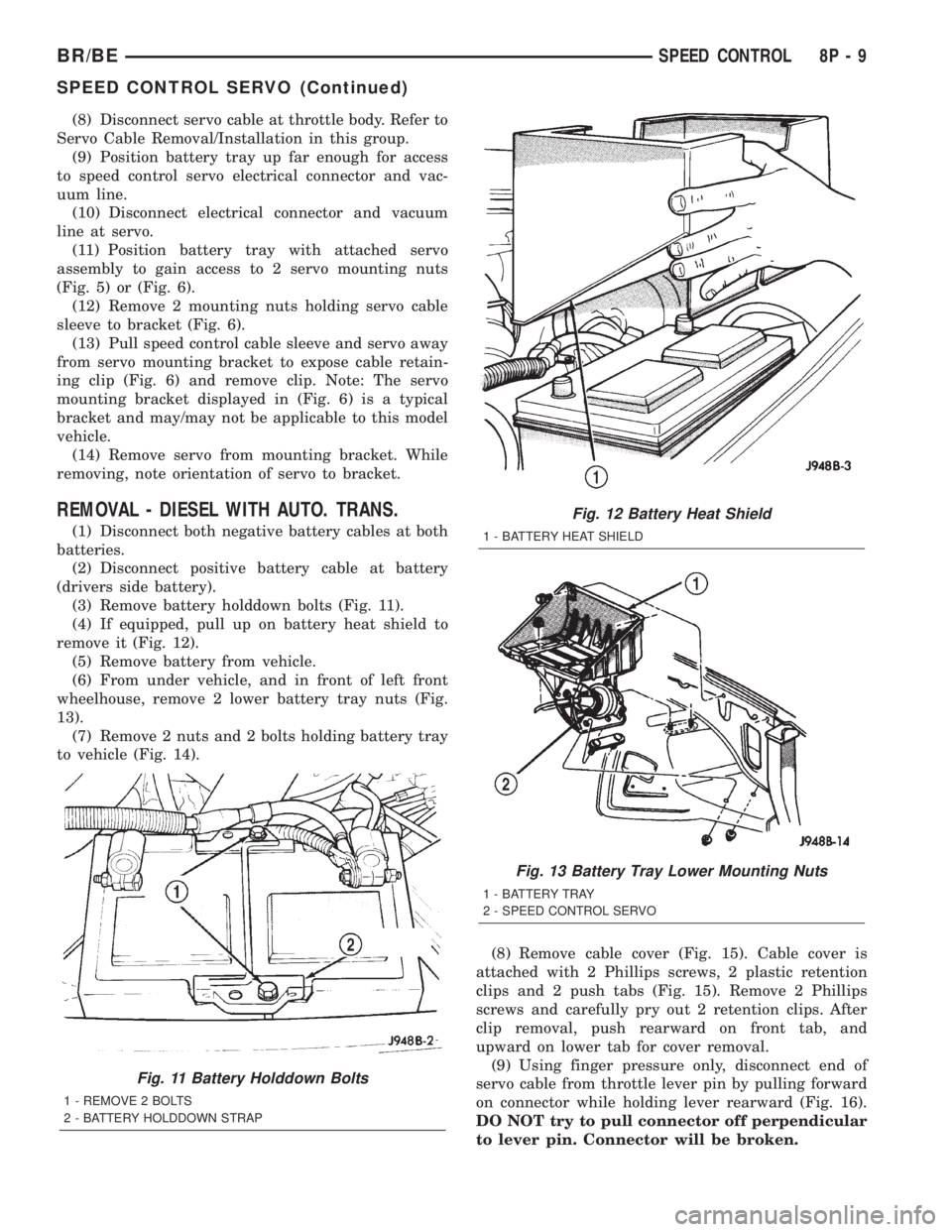
(8) Disconnect servo cable at throttle body. Refer to
Servo Cable Removal/Installation in this group.
(9) Position battery tray up far enough for access
to speed control servo electrical connector and vac-
uum line.
(10) Disconnect electrical connector and vacuum
line at servo.
(11) Position battery tray with attached servo
assembly to gain access to 2 servo mounting nuts
(Fig. 5) or (Fig. 6).
(12) Remove 2 mounting nuts holding servo cable
sleeve to bracket (Fig. 6).
(13) Pull speed control cable sleeve and servo away
from servo mounting bracket to expose cable retain-
ing clip (Fig. 6) and remove clip. Note: The servo
mounting bracket displayed in (Fig. 6) is a typical
bracket and may/may not be applicable to this model
vehicle.
(14) Remove servo from mounting bracket. While
removing, note orientation of servo to bracket.
REMOVAL - DIESEL WITH AUTO. TRANS.
(1) Disconnect both negative battery cables at both
batteries.
(2) Disconnect positive battery cable at battery
(drivers side battery).
(3) Remove battery holddown bolts (Fig. 11).
(4) If equipped, pull up on battery heat shield to
remove it (Fig. 12).
(5) Remove battery from vehicle.
(6) From under vehicle, and in front of left front
wheelhouse, remove 2 lower battery tray nuts (Fig.
13).
(7) Remove 2 nuts and 2 bolts holding battery tray
to vehicle (Fig. 14).
(8) Remove cable cover (Fig. 15). Cable cover is
attached with 2 Phillips screws, 2 plastic retention
clips and 2 push tabs (Fig. 15). Remove 2 Phillips
screws and carefully pry out 2 retention clips. After
clip removal, push rearward on front tab, and
upward on lower tab for cover removal.
(9) Using finger pressure only, disconnect end of
servo cable from throttle lever pin by pulling forward
on connector while holding lever rearward (Fig. 16).
DO NOT try to pull connector off perpendicular
to lever pin. Connector will be broken.
Fig. 11 Battery Holddown Bolts
1 - REMOVE 2 BOLTS
2 - BATTERY HOLDDOWN STRAP
Fig. 12 Battery Heat Shield
1 - BATTERY HEAT SHIELD
Fig. 13 Battery Tray Lower Mounting Nuts
1 - BATTERY TRAY
2 - SPEED CONTROL SERVO
BR/BESPEED CONTROL 8P - 9
SPEED CONTROL SERVO (Continued)
Page 634 of 2255
INSTALLATION
INSTALLATION
V-8 ENGINE
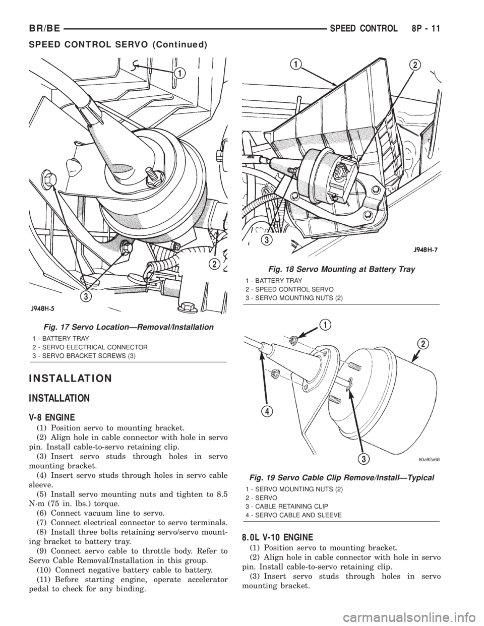
(1) Position servo to mounting bracket.
(2) Align hole in cable connector with hole in servo
pin. Install cable-to-servo retaining clip.
(3) Insert servo studs through holes in servo
mounting bracket.
(4) Insert servo studs through holes in servo cable
sleeve.
(5) Install servo mounting nuts and tighten to 8.5
N´m (75 in. lbs.) torque.
(6) Connect vacuum line to servo.
(7) Connect electrical connector to servo terminals.
(8) Install three bolts retaining servo/servo mount-
ing bracket to battery tray.
(9) Connect servo cable to throttle body. Refer to
Servo Cable Removal/Installation in this group.
(10) Connect negative battery cable to battery.
(11) Before starting engine, operate accelerator
pedal to check for any binding.
8.0L V-10 ENGINE
(1) Position servo to mounting bracket.
(2) Align hole in cable connector with hole in servo
pin. Install cable-to-servo retaining clip.
(3) Insert servo studs through holes in servo
mounting bracket.
Fig. 17 Servo LocationÐRemoval/Installation
1 - BATTERY TRAY
2 - SERVO ELECTRICAL CONNECTOR
3 - SERVO BRACKET SCREWS (3)
Fig. 18 Servo Mounting at Battery Tray
1 - BATTERY TRAY
2 - SPEED CONTROL SERVO
3 - SERVO MOUNTING NUTS (2)
Fig. 19 Servo Cable Clip Remove/InstallÐTypical
1 - SERVO MOUNTING NUTS (2)
2 - SERVO
3 - CABLE RETAINING CLIP
4 - SERVO CABLE AND SLEEVE
BR/BESPEED CONTROL 8P - 11
SPEED CONTROL SERVO (Continued)
Page 635 of 2255
(4) Insert servo studs through holes in servo cable
sleeve.
(5) Install servo mounting nuts and tighten to 8.5
N´m (75 in. lbs.) torque.
(6) Connect vacuum line to servo.
(7) Connect electrical connector to servo terminals.
(8) Connect servo cable to throttle body. Refer to
Servo Cable Removal/Installation in this group.
(9) Install battery tray. Tighten all battery tray
mounting hardware to 16 N´m (140 in. lbs.) torque.
(10) Position battery into battery tray.
(11) If equipped, install battery heat shield.
(12) Install battery holddown clamp. Tighten bolt
to 4 N´m (35 in. lbs.) torque.
(13) Connect positive battery cable to battery.
(14) Connect negative battery cable to battery.
(15) Before starting engine, operate accelerator
pedal to check for any binding.
INSTALLATION - DIESEL WITH AUTO. TRANS.
(1) Position servo to mounting bracket.
(2) Align hole in cable connector with hole in servo
pin. Install cable-to-servo retaining clip.
(3) Insert servo studs through holes in servo
mounting bracket.
(4) Insert servo studs through holes in servo cable
sleeve.
(5) Install servo mounting nuts and tighten to 8.5
N´m (75 in. lbs.) torque.
(6) Connect vacuum line to servo.
(7) Connect electrical connector to servo terminals.
(8) Connect servo cable to throttle lever by push-
ing cable connector rearward onto lever pin while
holding lever forward.
(9) Install battery tray. Tighten all battery tray
mounting hardware to 16 N´m (140 in. lbs.) torque.
(10) Position battery into battery tray.
(11) If equipped, install battery heat shield.
(12) Install battery holddown clamp. Tighten bolt
to 4 N´m (35 in. lbs.) torque.
(13) Connect positive battery cable to battery.
(14) Connect negative battery cables to both bat-
teries.
(15) Before starting engine, operate accelerator
pedal to check for any binding.
(16) Install cable/lever cover.
SWITCH
DESCRIPTION
Gas Engines and Diesel With Auto. Trans.
There are two separate switch pods that operate
the speed control system. The steering-wheel-
mounted switches use multiplexed circuits to provideinputs to the Powertrain Control Module (PCM) for
ON, OFF, RESUME, ACCELERATE, SET, DECEL
and CANCEL modes. Refer to the owner's manual for
more information on speed control switch functions
and setting procedures.
The individual switches cannot be repaired. If one
switch fails, the entire switch module must be
replaced.
Diesel With Manual Trans.
There are two separate switch pods that operate
the speed control system. The steering-wheel-
mounted switches use multiplexed circuits to provide
inputs to the Engine Control Module (ECM) for ON,
OFF, RESUME, ACCELERATE, SET, DECEL and
CANCEL modes. Refer to the owner's manual for
more information on speed control switch functions
and setting procedures.
The individual switches cannot be repaired. If one
switch fails, the entire switch module must be
replaced.
OPERATION
Gas Engines and Diesel With Auto. Trans.
When speed control is selected by depressing the
ON, OFF switch, the Powertrain Control Module
(PCM) allows a set speed to be stored in its RAM for
speed control. To store a set speed, depress the SET
switch while the vehicle is moving at a speed
between approximately 35 and 85 mph. In order for
the speed control to engage, the brakes cannot be
applied, nor can the gear selector be indicating the
transmission is in Park or Neutral.
The speed control can be disengaged manually by:
²Stepping on the brake pedal.
²Depressing the OFF switch.
²Depressing the CANCEL switch.
The speed control can be disengaged also by any of
the following conditions:
²An indication of Park or Neutral.
²The vehicle speed signal increases at a rate of
10 mph per second (indicates that the co-efficient of
friction between the road surface and tires is
extremely low).
²Depressing the clutch pedal.
²Excessive engine rpm (indicates that the trans-
mission may be in a low gear).
²The vehicle speed signal decreases at a rate of
10 mph per second (indicates that the vehicle may
have decelerated at an extremely high rate).
²If the actual speed is not within 20 mph of the
set speed.
The previous disengagement conditions are pro-
grammed for added safety.
8P - 12 SPEED CONTROLBR/BE
SPEED CONTROL SERVO (Continued)
Page 669 of 2255
DESCRIPTION - SECTION IDENTIFICATION AND
INFORMATION
The wiring diagrams are grouped into individual
sections. If a component is most likely found in a par-
ticular group, it will be shown complete (all wires,
connectors, and pins) within that group. For exam-
ple, the Auto Shutdown Relay is most likely to be
found in Group 30, so it is shown there complete. It
can, however, be shown partially in another group if
it contains some associated wiring.
Splice diagrams in Section 8W-70 show the entire
splice and provide references to other sections the
splices serves. Section 8W-70 only contains splice dia-
grams that are not shown in their entirety some-
where else in the wiring diagrams.
Section 8W-80 shows each connector and the cir-
cuits involved with that connector. The connectors
are identified using the name/number on the dia-
gram pages.
WIRING SECTION CHART
GROUP TOPIC
8W-01 thru
8W-09General information and Diagram
Overview
8W-10 thru
8W-19Main Sources of Power and
Vehicle Grounding
8W-20 thru
8W-29Starting and Charging
8W-30 thru
8W-39Powertrain/Drivetrain Systems
GROUP TOPIC
8W-40 thru
8W-49Body Electrical items and A/C
8W-50 thru
8W-59Exterior Lighting, Wipers and
Trailer Tow
8W-60 thru
8W-69Power Accessories
8W-70 Splice Information
8W-80 Connector Pin Outs
8W-91 Connector, Ground and Splice
Locations
DESCRIPTION - CONNECTOR, GROUND AND
SPLICE INFORMATION
CAUTION: Not all connectors are serviced. Some
connectors are serviced only with a harness. A typ-
ical example might be the Supplemental Restraint
System connectors. Always check parts availability
before attempting a repair.
IDENTIFICATION
In-line connectors are identified by a number, as
follows:
²In-line connectors located in the engine compart-
ment are C100 series numbers
²In-line connectors located in the Instrument
Panel area are C200 series numbers.
²In-line connectors located in the body are C300
series numbers.
²Jumper harness connectors are C400 series
numbers.
²Grounds and ground connectors are identified
with a ªGº and follow the same series numbering as
the in-line connectors.
²Splices are identified with an ªSº and follow the
same series numbering as the in-line connectors.
²Component connectors are identified by the com-
ponent name instead of a number. Multiple connec-
tors on a component use a C1, C2, etc. identifier.
LOCATIONS
Section 8W-91 contains connector/ground/splice
location illustrations. The illustrations contain the
connector name (or number)/ground number/splice
number and component identification. Connector/
ground/splice location charts in section 8W-91 refer-
ence the figure numbers of the illustrations.
The abbreviation T/O is used in the component
location section to indicate a point in which the wir-
ing harness branches out to a component. The abbre-
viation N/S means Not Shown in the illustrations
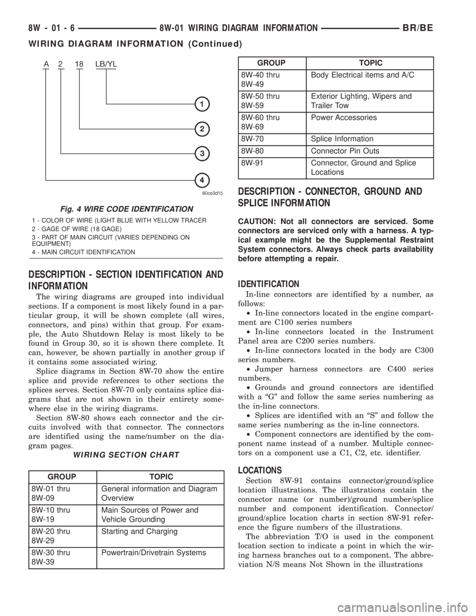
Fig. 4 WIRE CODE IDENTIFICATION
1 - COLOR OF WIRE (LIGHT BLUE WITH YELLOW TRACER
2 - GAGE OF WIRE (18 GAGE)
3 - PART OF MAIN CIRCUIT (VARIES DEPENDING ON
EQUIPMENT)
4 - MAIN CIRCUIT IDENTIFICATION
8W - 01 - 6 8W-01 WIRING DIAGRAM INFORMATIONBR/BE
WIRING DIAGRAM INFORMATION (Continued)
Page 1060 of 2255
8W-97 POWER DISTRIBUTION
TABLE OF CONTENTS
page page
POWER DISTRIBUTION
DESCRIPTION..........................1
OPERATION............................1
SPECIAL TOOLS
POWER DISTRIBUTION SYSTEMS.........2
CIGAR LIGHTER OUTLET
DESCRIPTION..........................2
OPERATION............................2
DIAGNOSIS AND TESTING - CIGAR LIGHTER
OUTLET.............................2
REMOVAL.............................3
INSTALLATION..........................4
CIRCUIT BREAKER
DESCRIPTION..........................4
DIAGNOSIS AND TESTING - CIRCUIT
BREAKER............................4
GENERATOR CARTRIDGE FUSE
DESCRIPTION..........................4
OPERATION............................4
REMOVAL.............................4
INSTALLATION..........................4
IOD FUSE
DESCRIPTION..........................5
OPERATION............................5
REMOVAL.............................6
INSTALLATION..........................6
JUNCTION BLOCK
DESCRIPTION..........................6
OPERATION............................7
DIAGNOSIS AND TESTING - JUNCTION
BLOCK..............................7
REMOVAL.............................7
INSTALLATION..........................8POWER DISTRIBUTION CENTER
DESCRIPTION..........................8
OPERATION............................8
REMOVAL.............................8
INSTALLATION.........................10
POWER OUTLET
DESCRIPTION.........................10
OPERATION...........................10
DIAGNOSIS AND TESTING - POWER OUTLET . 10
REMOVAL.............................11
INSTALLATION.........................11
HORN RELAY
DESCRIPTION.........................12
DIAGNOSIS AND TESTING - HORN RELAY . . . 12
REMOVAL.............................12
INSTALLATION.........................12
HEADLAMP RELAY
DESCRIPTION.........................13
REMOVAL.............................13
INSTALLATION.........................13
MICRO-RELAY
DESCRIPTION.........................13
OPERATION...........................14
DIAGNOSIS AND TESTING - MICRO-RELAY . . 14
REMOVAL.............................14
INSTALLATION.........................14
RELAY
DESCRIPTION.........................14
OPERATION...........................14
DIAGNOSIS AND TESTING - RELAY.........15
REMOVAL.............................15
INSTALLATION.........................15
POWER DISTRIBUTION
DESCRIPTION
This group covers the various standard and
optional power distribution components used on this
model. The power distribution system for this vehicle
consists of the following components:
²Power Distribution Center (PDC)
²Junction Block (JB).
The power distribution system also incorporates
various types of circuit control and protection fea-
tures, including:
²Automatic resetting circuit breakers
²Blade-type fuses²Cartridge fuses
²Circuit splice blocks
²Flashers
²Relays.
Following are general descriptions of the major
components in the power distribution system. See the
owner's manual in the vehicle glove box for more
information on the features and use of all of the
power distribution system components. Refer toWir-
ing Diagramsfor complete circuit diagrams for the
various power distribution system components.
OPERATION
The power distribution system for this vehicle is
designed to provide safe, reliable, and centralized dis-
BR/BE8W-97 POWER DISTRIBUTION 8W - 97 - 1
Page 1071 of 2255
(4) Press firmly on the cigar lighter or power out-
let receptacle base until the retaining bosses of the
mount are fully engaged in their receptacles.
(5) Install the cigar lighter knob and element into
the cigar lighter receptacle base, or the protective cap
into the power outlet receptacle base.
(6) Reconnect the battery negative cable.
HORN RELAY
DESCRIPTION
The horn relay is a International Standards Orga-
nization (ISO) micro-relay. The terminal designations
and functions are the same as a conventional ISO
relay. However, the micro-relay terminal orientation
(or footprint) is different, current capacity is lower,
and the relay case dimensions are smaller than those
of the conventional ISO relay.
The horn relay is a electromechanical device that
switches battery current to the horn when the horn
switch or when the high-line or premium Central
Timer Module (CTM) grounds the relay coil. See
Horn Relay in the Diagnosis and Testing section of
this group for more information.
The horn relay is located in the Power Distribution
Center (PDC), in the engine compartment. Refer to
the PDC label for relay identification and location.
If a problem is encountered with a continuously
sounding horn, it can usually be quickly resolved by
removing the horn relay from the PDC until further
diagnosis is completed.
The horn relay cannot be repaired and, if faulty or
damaged, it must be replaced.
DIAGNOSIS AND TESTING - HORN RELAY
The headlamp (or security) relay and the horn
relay are located in the Power Distribution Center
(PDC) in the engine compartment. Each of these
relays can be tested as described in the following pro-
cedure, however the circuits they are used in do vary.
To test the relay circuits, refer to the circuit descrip-
tions and diagrams in Wiring Diagrams.
WARNING: ON VEHICLES EQUIPPED WITH AIR-
BAGS, REFER TO THE RESTRAINTS SECTION OF
THE SERVICE MANUAL BEFORE ATTEMPTING ANY
STEERING WHEEL, STEERING COLUMN, OR
INSTRUMENT PANEL COMPONENT DIAGNOSIS OR
SERVICE. FAILURE TO TAKE THE PROPER PRE-
CAUTIONS COULD RESULT IN ACCIDENTAL AIR-
BAG DEPLOYMENT AND POSSIBLE PERSONAL
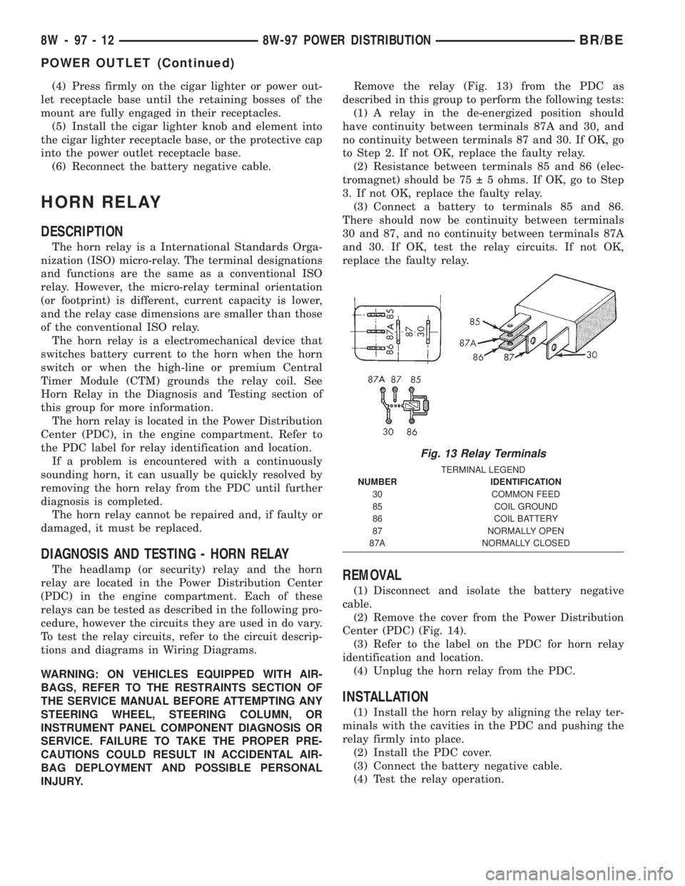
INJURY.Remove the relay (Fig. 13) from the PDC as
described in this group to perform the following tests:
(1) A relay in the de-energized position should
have continuity between terminals 87A and 30, and
no continuity between terminals 87 and 30. If OK, go
to Step 2. If not OK, replace the faulty relay.
(2) Resistance between terminals 85 and 86 (elec-
tromagnet) should be 75 5 ohms. If OK, go to Step
3. If not OK, replace the faulty relay.
(3) Connect a battery to terminals 85 and 86.
There should now be continuity between terminals
30 and 87, and no continuity between terminals 87A
and 30. If OK, test the relay circuits. If not OK,
replace the faulty relay.REMOVAL
(1) Disconnect and isolate the battery negative
cable.
(2) Remove the cover from the Power Distribution
Center (PDC) (Fig. 14).
(3) Refer to the label on the PDC for horn relay
identification and location.
(4) Unplug the horn relay from the PDC.
INSTALLATION
(1) Install the horn relay by aligning the relay ter-
minals with the cavities in the PDC and pushing the
relay firmly into place.
(2) Install the PDC cover.
(3) Connect the battery negative cable.
(4) Test the relay operation.
Fig. 13 Relay Terminals
TERMINAL LEGEND
NUMBER IDENTIFICATION
30 COMMON FEED
85 COIL GROUND
86 COIL BATTERY
87 NORMALLY OPEN
87A NORMALLY CLOSED
8W - 97 - 12 8W-97 POWER DISTRIBUTIONBR/BE
POWER OUTLET (Continued)
Page 1072 of 2255
HEADLAMP RELAY
DESCRIPTION
The headlamp (or security) relay is a International
Standards Organization (ISO) micro-relay. The termi-
nal designations and functions are the same as a con-
ventional ISO relay. However, the micro-relay
terminal orientation (or footprint) is different, cur-
rent capacity is lower, and the relay case dimensions
are smaller than those of the conventional ISO relay.
The headlamp relay is a electromechanical device
that switches battery current to the headlamps when
the high-line or premium Central Timer Module
(CTM) grounds the relay coil. See Headlamp Relay in
the Diagnosis and Testing section of this group for
more information.
The headlamp (or security) relay is located in the
Power Distribution Center (PDC), in the engine com-
partment. Refer to the PDC label for relay identifica-
tion and location.
The headlamp relay cannot be repaired and, if
faulty or damaged, it must be replaced.
REMOVAL
(1) Disconnect and isolate the battery negative
cable.
(2) Remove the cover from the Power Distribution
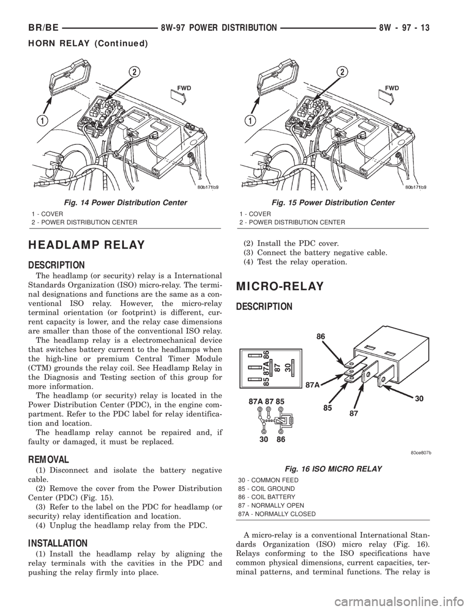
Center (PDC) (Fig. 15).
(3) Refer to the label on the PDC for headlamp (or
security) relay identification and location.
(4) Unplug the headlamp relay from the PDC.
INSTALLATION
(1) Install the headlamp relay by aligning the
relay terminals with the cavities in the PDC and
pushing the relay firmly into place.(2) Install the PDC cover.
(3) Connect the battery negative cable.
(4) Test the relay operation.
MICRO-RELAY
DESCRIPTION
A micro-relay is a conventional International Stan-
dards Organization (ISO) micro relay (Fig. 16).
Relays conforming to the ISO specifications have
common physical dimensions, current capacities, ter-
minal patterns, and terminal functions. The relay is
Fig. 14 Power Distribution Center
1 - COVER
2 - POWER DISTRIBUTION CENTER
Fig. 15 Power Distribution Center
1 - COVER
2 - POWER DISTRIBUTION CENTER
Fig. 16 ISO MICRO RELAY
30 - COMMON FEED
85 - COIL GROUND
86 - COIL BATTERY
87 - NORMALLY OPEN
87A - NORMALLY CLOSED
BR/BE8W-97 POWER DISTRIBUTION 8W - 97 - 13
HORN RELAY (Continued)
Page 1150 of 2255
AIR CLEANER ELEMENT
REMOVAL - 8.0L
For air cleaner element required maintenance
schedules (listed in time or mileage intervals), refer
to 0, Lubrication and Maintenance.
A small amount of engine oil wetting the inside of
the air cleaner housing is normal. When servicing,
wipe out oil from air cleaner housing.
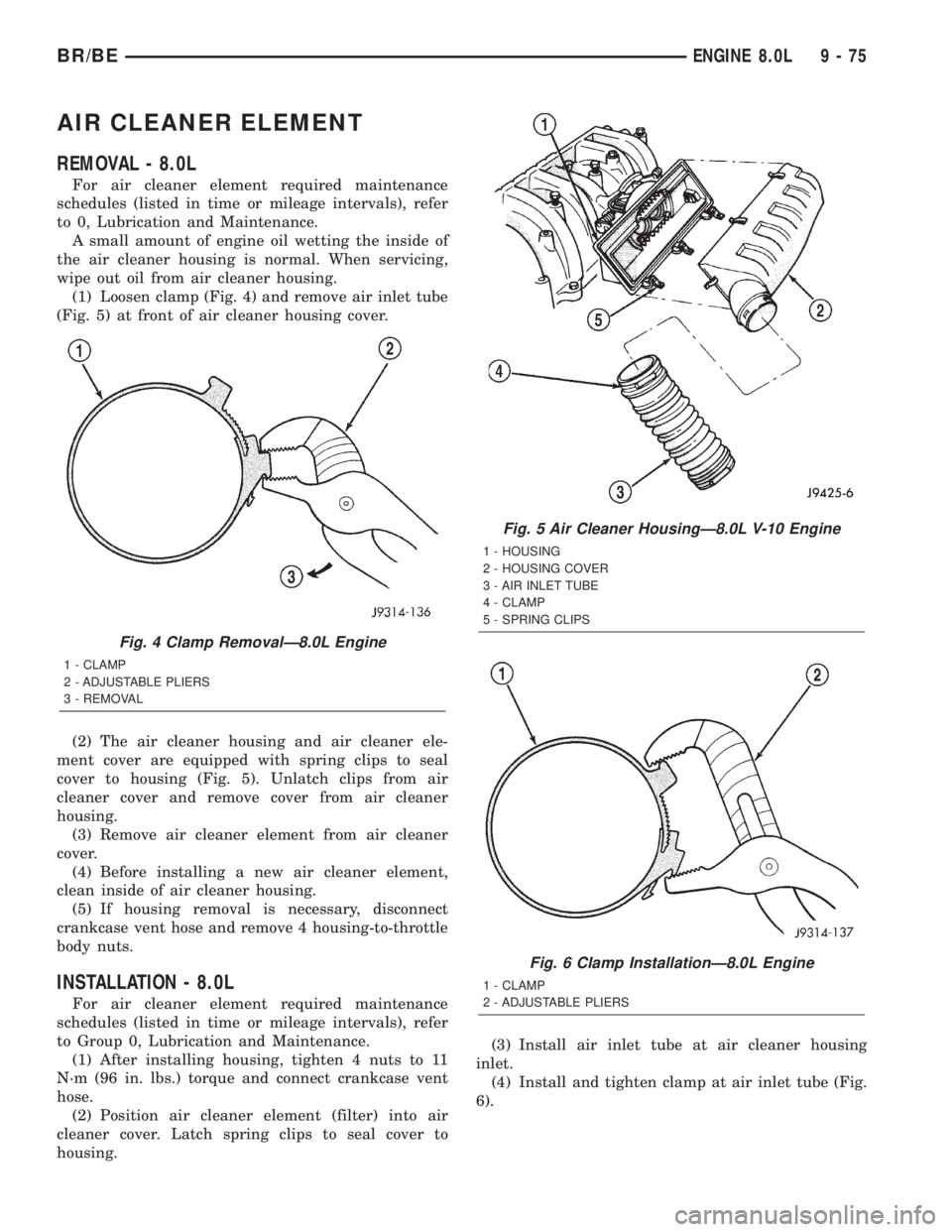
(1) Loosen clamp (Fig. 4) and remove air inlet tube
(Fig. 5) at front of air cleaner housing cover.
(2) The air cleaner housing and air cleaner ele-
ment cover are equipped with spring clips to seal
cover to housing (Fig. 5). Unlatch clips from air
cleaner cover and remove cover from air cleaner
housing.
(3) Remove air cleaner element from air cleaner
cover.
(4) Before installing a new air cleaner element,
clean inside of air cleaner housing.
(5) If housing removal is necessary, disconnect
crankcase vent hose and remove 4 housing-to-throttle
body nuts.
INSTALLATION - 8.0L
For air cleaner element required maintenance
schedules (listed in time or mileage intervals), refer
to Group 0, Lubrication and Maintenance.
(1) After installing housing, tighten 4 nuts to 11
N´m (96 in. lbs.) torque and connect crankcase vent
hose.
(2) Position air cleaner element (filter) into air
cleaner cover. Latch spring clips to seal cover to
housing.(3) Install air inlet tube at air cleaner housing
inlet.
(4) Install and tighten clamp at air inlet tube (Fig.
6).
Fig. 4 Clamp RemovalÐ8.0L Engine
1 - CLAMP
2 - ADJUSTABLE PLIERS
3 - REMOVAL
Fig. 5 Air Cleaner HousingÐ8.0L V-10 Engine
1 - HOUSING
2 - HOUSING COVER
3 - AIR INLET TUBE
4 - CLAMP
5 - SPRING CLIPS
Fig. 6 Clamp InstallationÐ8.0L Engine
1 - CLAMP
2 - ADJUSTABLE PLIERS
BR/BEENGINE 8.0L 9 - 75
Page 1162 of 2255
CONNECTING ROD BEARINGS
STANDARD PROCEDURE - CONNECTING ROD
BEARING FITTING
Fit all rods on a bank until completed. DO NOT
alternate from one bank to another, because connect-
ing rods and pistons are not interchangeable from
one bank to another.
The bearing caps are not interchangeable and
should be marked at removal to ensure correct
assembly.
Each bearing cap has a small V-groove across the
parting face. When installing the lower bearing shell,
be certain that the V-groove in the shell is in line
with the V-groove in the cap. This provides lubrica-
tion of the cylinder wall in the opposite bank.
The bearing shells must be installed so that the
tangs are in the machined grooves in the rods and
caps.
Limits of taper or out-of-round on any crankshaft
journals should be held to 0.025 mm (0.001 in.).
Bearings are available in 0.025 mm (0.001 in.), 0.051
mm (0.002 in.), 0.076 mm (0.003 in.), 0.254 mm
(0.010 in.) and 0.305 mm (0.012 in.) undersize.Install the bearings in pairs. DO NOT use a new
bearing half with an old bearing half. DO NOT
file the rods or bearing caps.
CRANKSHAFT
REMOVAL
When a crankshaft is replaced, all main and con-
necting rod bearings should be replaced with new
bearings. Therefore, selective fitting of the bearings
is not required when a crankshaft and bearings are
replaced.
(1) Remove the oil pan and oil pickup tube (refer
to Oil Pan in this section for correct procedure).
(2) Remove the timing chain cover and gasket.
Remove and discard the front crankshaft oil seal and
cover gasket.
(3) Remove Transmission (refer to Group 21,
Transmission).
(4) Remove the rear seal retainer (refer to Crank-
shaft Rear Seal Retainer in this section for correct
procedure).
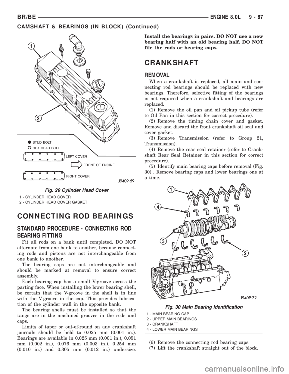
(5) Identify main bearing caps before removal (Fig.
30) . Remove bearing caps and lower bearings one at
a time.
(6) Remove the connecting rod bearing caps.
(7) Lift the crankshaft straight out of the block.
Fig. 29 Cylinder Head Cover
1 - CYLINDER HEAD COVER
2 - CYLINDER HEAD COVER GASKET
Fig. 30 Main Bearing Identification
1 - MAIN BEARING CAP
2 - UPPER MAIN BEARINGS
3 - CRANKSHAFT
4 - LOWER MAIN BEARINGS
BR/BEENGINE 8.0L 9 - 87
CAMSHAFT & BEARINGS (IN BLOCK) (Continued)
Page 1212 of 2255
(b) Install the rear line bundle (cyls. #3, 5, and
6), and tighten the threads at the head and pump
by hand.
(c) Torque the connections at the cylinder head
first. Torque connections to 38 N´m (28 ft. lbs.).
(d) Torque the line connections at the injection
pump to 24 N´m (18 ft. lbs.).
(e) Install the front line bundle (cyls. #1, 2, and
4) following the same procedure used for the rear
line bundle.
(f) Torque the connections at the cylinder head
first. Torque connections to 38 N´m (28 ft. lbs.).
(g) Torque the line connections at the injection
pump to 24 N´m (18 ft. lbs.).
(h) Install the injection line support bracket to
intake cover/cylinder head bolts and torque to 24
N´m (18 ft. lbs.).
(16) Install the engine lift bracket at the rear of
cylinder head. Torque to 77 N´m (57 ft. lbs.).
(17) Install the fuel filter to injection pump low
pressure line. Inspect and replace sealing washers if
necessary. Torque banjo bolts to 24 N´m (18 ft. lbs.).
(18) Using new gaskets, install the intake grid
heater and air inlet housing. Torque bolts to 24 N´m
(18 ft. lbs.).(19) Connect the APPS connector (Fig. 17).
(20) Install the APPS assembly. to the cylinder
head bracket and torque bolts to 12 N´m (105 in.
lbs.).
(21) Install the throttle linkage cover (Fig. 15).
(22) Install the charge air cooler-to-air inlet hous-
ing duct assembly. Torque all clamps to 11 N´m (100
in. lbs.).
(23) Connect intake grid heater wires.
(24) Fasten engine harness to front of cylinder
head with bolt.
(25) Install engine harness ground wire and torque
bolt to 24 N´m (18 ft. lbs.).
(26) Connect engine coolant temperature sensor
connector.
(27) Connect radiator upper hose to thermostat
housing.
(28) Install generator upper bracket and torque
bolts to 41 N´m (31 ft. lbs.).
(29) Install accessory drive belt (Refer to 7 -
COOLING/ACCESSORY DRIVE/DRIVE BELTS -
INSTALLATION).
(30) Install exhaust manifold/turbocharger assem-
bly. and start all bolts/spacers by hand. Torque bolts
to 43 N´m (32 ft. lbs.).
(31) Connect turbocharger oil drain tube.
(32) Perform the turbocharger pre-lube procedure.
Refer to Group 11, Exhaust System and Turbo-
charger for the correct procedure.
(33) Connect the turbocharger oil supply line.
(34) Install air cleaner housing and duct.
(35) Raise vehicle on hoist.
(36) Install exhaust pipe to turbocharger elbow
(Fig. 14). Torque bolts to 34 N´m (25 ft. lbs.).
(37) Lower vehicle.
(38) Fill engine coolant (Refer to 7 - COOLING -
STANDARD PROCEDURE).
(39) Start engine and check for leaks.
CYLINDER HEAD COVER(S)
REMOVAL
(1) Disconnect both battery negative cables.
(2) Loosen the five (5) cylinder head cover bolts
(Fig. 34) . Remove the front three bolts and leave the
rear two bolts in the cover.
(3) Lift cover off of cylinder head.
CLEANING
Using a suitable solvent, Clean and dry gasket
mating surfaces on cylinder head and cover. Wipe
gasket dry and inspect for re-use.
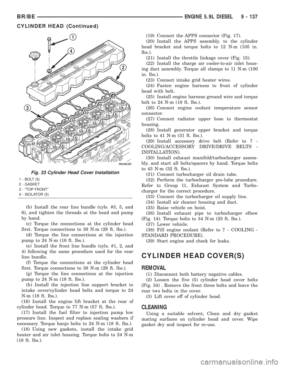
Fig. 33 Cylinder Head Cover Installation
1 - BOLT (5)
2 - GASKET
3 - ªTOP FRONTº
4 - ISOLATOR (5)
BR/BEENGINE 5.9L DIESEL 9 - 137
CYLINDER HEAD (Continued)