group 19 DODGE RAM 2002 Service Manual PDF
[x] Cancel search | Manufacturer: DODGE, Model Year: 2002, Model line: RAM, Model: DODGE RAM 2002Pages: 2255, PDF Size: 62.07 MB
Page 1583 of 2255
(a) Loosen locknut on each band adjusting screw
4-5 turns.
(b) Tighten both adjusting screws to 8 N´m (72
in. lbs.).
(c) Back off front band adjusting screw 2-7/8
turns.
(d) Back off rear band adjusting screw 2 turns.
(e) Hold each adjusting screw in position and
tighten locknut to 34 N´m (25 ft. lbs.) torque.
(2) Install magnet in oil pan. Magnet seats on
small protrusion at corner of pan.
(3) Position new oil pan gasket on case and install
oil pan. Tighten pan bolts to 13.6 N´m (125 in. lbs.).
(4) Install throttle valve and shift selector levers
on valve body manual lever shaft.
(5) Apply small quantity of dielectric grease to ter-
minal pins of solenoid case connector and neutral
switch.
(6) Fill transmission with recommended fluid.
Refer to Service Procedures section of this group.
INSTALLATION
(1) Check torque converter hub and hub drive
notches for sharp edges burrs, scratches, or nicks.
Polish the hub and notches with 320/400 grit paper
and crocus cloth if necessary. The hub must be
smooth to avoid damaging pump seal at installation.
(2) Lubricate pocket in the rear oil pump seal lip
with transmission fluid.(3) Lubricate converter pilot hub of the crankshaft
with a light coating of MopartHigh Temp Grease.
(4) Align and install converter in oil pump.
(5) Carefully insert converter in oil pump. Then
rotate converter back and forth until fully seated in
pump gears.
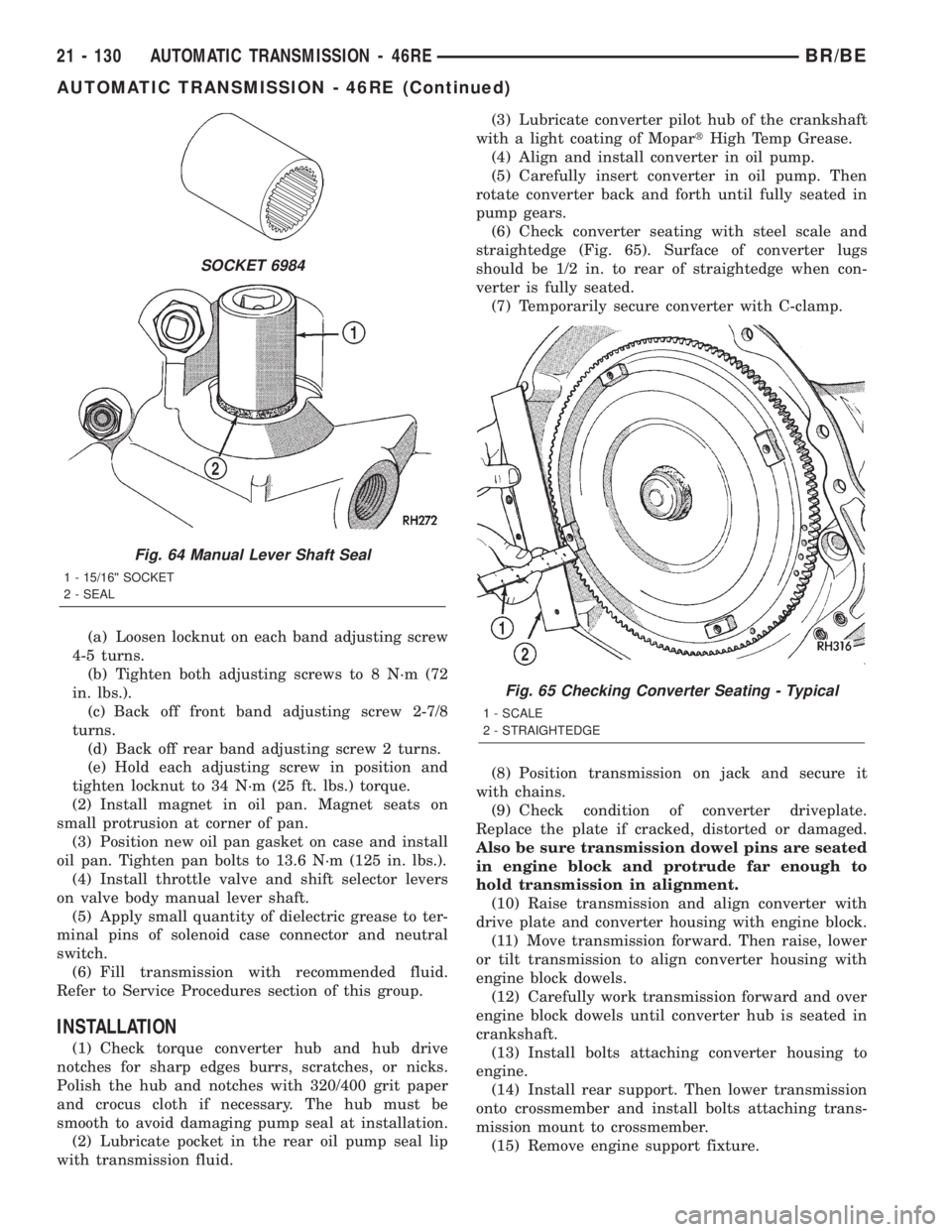
(6) Check converter seating with steel scale and
straightedge (Fig. 65). Surface of converter lugs
should be 1/2 in. to rear of straightedge when con-
verter is fully seated.
(7) Temporarily secure converter with C-clamp.
(8) Position transmission on jack and secure it
with chains.
(9) Check condition of converter driveplate.
Replace the plate if cracked, distorted or damaged.
Also be sure transmission dowel pins are seated
in engine block and protrude far enough to
hold transmission in alignment.
(10) Raise transmission and align converter with
drive plate and converter housing with engine block.
(11) Move transmission forward. Then raise, lower
or tilt transmission to align converter housing with
engine block dowels.
(12) Carefully work transmission forward and over
engine block dowels until converter hub is seated in
crankshaft.
(13) Install bolts attaching converter housing to
engine.
(14) Install rear support. Then lower transmission
onto crossmember and install bolts attaching trans-
mission mount to crossmember.
(15) Remove engine support fixture.
SOCKET 6984
Fig. 64 Manual Lever Shaft Seal
1 - 15/16©© SOCKET
2 - SEAL
Fig. 65 Checking Converter Seating - Typical
1 - SCALE
2 - STRAIGHTEDGE
21 - 130 AUTOMATIC TRANSMISSION - 46REBR/BE
AUTOMATIC TRANSMISSION - 46RE (Continued)
Page 1727 of 2255
scored, either polish it with crocus cloth or replace
converter.
(5) Install new pump seal, O-ring, and gasket.
Replace oil pump if cracked, porous or damaged in
any way. Be sure to loosen the front band before
installing the oil pump, damage to the oil pump seal
may occur if the band is still tightened to the front
clutch retainer.
(6) Loosen kickdown lever pin access plug three
turns. Apply LoctiteŸ 592, or PermatextNo.2to
plug threads and tighten plug to 17 N´m (150 in. lbs.)
torque.
(7) Adjust front band.
(8) Lubricate pump seal and converter hub with
transmission fluid or petroleum jelly and install con-
verter.
(9) Install transmission and converter housing
dust shield.(10) Lower vehicle.
DIAGNOSIS AND TESTING - DIAGNOSIS
CHARTS
The diagnosis charts provide additional reference
when diagnosing a transmission fault. The charts
provide general information on a variety of transmis-
sion, overdrive unit and converter clutch fault condi-
tions.
The hydraulic flow charts in the Schematics and
Diagrams section of this group, outline fluid flow and
hydraulic circuitry. Circuit operation is provided for
PARK, NEUTRAL, FIRST, SECOND, THIRD,
FOURTH, MANUAL FIRST, MANUAL SECOND,
and REVERSE gear ranges. Normal working pres-
sures are also supplied for each of the gear ranges.
DIAGNOSIS CHARTS
CONDITION POSSIBLE CAUSES CORRECTION
HARSH ENGAGEMENT
(FROM NEUTRAL TO
DRIVE OR REVERSE)1. Fluid Level Low. 1. Add Fluid
2. Throttle Linkage Mis-adjusted. 2. Adjust linkage - setting may be too long.
3. Mount and Driveline Bolts Loose. 3. Check engine mount, transmission
mount, propeller shaft, rear spring to body
bolts, rear control arms, crossmember and
axle bolt torque. Tighten loose bolts and
replace missing bolts.
4. U-Joint Worn/Broken. 4. Remove propeller shaft and replace
U-Joint.
5. Axle Backlash Incorrect. 5. Check per Service Manual. Correct as
needed.
6. Hydraulic Pressure Incorrect. 6. Check pressure. Remove, overhaul or
adjust valve body as needed.
7. Band Mis-adjusted. 7. Adjust rear band.
8. Valve Body Check Balls Missing. 8. Inspect valve body for proper check ball
installation.
9. Axle Pinion Flange Loose. 9. Replace nut and check pinion threads
before installing new nut. Replace pinion
gear if threads are damaged.
10. Clutch, band or planetary
component damaged.10. Remove, disassemble and repair
transmission as necessary.
11. Converter Clutch Faulty. 11. Replace converter and flush cooler and
line before installing new converter.
21 - 274 AUTOMATIC TRANSMISSION - 47REBR/BE
AUTOMATIC TRANSMISSION - 47RE (Continued)
Page 1969 of 2255
DIAGNOSIS AND TESTING
DIAGNOSIS AND TESTING - WATER LEAKS
Water leaks can be caused by poor sealing,
improper body component alignment, body seam
porosity, missing plugs, or blocked drain holes. Cen-
trifugal and gravitational force can cause water to
drip from a location away from the actual leak point,
making leak detection difficult. All body sealing
points should be water tight in normal wet-driving
conditions. Water flowing downward from the front of
the vehicle should not enter the passenger or luggage
compartment. Moving sealing surfaces will not
always seal water tight under all conditions. At
times, side glass or door seals will allow water to
enter the passenger compartment during high pres-
sure washing or hard driving rain (severe) condi-
tions. Overcompensating on door or glass
adjustments to stop a water leak that occurs under
severe conditions can cause premature seal wear and
excessive closing or latching effort. After completing
a repair, water test vehicle to verify leak has stopped
before returning vehicle to use.
VISUAL INSPECTION BEFORE WATER LEAK TESTS
Verify that floor and body plugs are in place, body
drains are clear, and body components are properly
aligned and sealed. If component alignment or seal-
ing is necessary, refer to the appropriate section of
this group for proper procedures.
WATER LEAK TESTS
WARNING: DO NOT USE ELECTRIC SHOP LIGHTS
OR TOOLS IN WATER TEST AREA. PERSONAL
INJURY CAN RESULT.
When the conditions causing a water leak have
been determined, simulate the conditions as closely
as possible.
²If a leak occurs with the vehicle parked in a
steady light rain, flood the leak area with an open-
ended garden hose.²If a leak occurs while driving at highway speeds
in a steady rain, test the leak area with a reasonable
velocity stream or fan spray of water. Direct the
spray in a direction comparable to actual conditions.
²If a leak occurs when the vehicle is parked on an
incline, hoist the end or side of the vehicle to simu-
late this condition. This method can be used when
the leak occurs when the vehicle accelerates, stops or
turns. If the leak occurs on acceleration, hoist the
front of the vehicle. If the leak occurs when braking,
hoist the back of the vehicle. If the leak occurs on left
turns, hoist the left side of the vehicle. If the leak
occurs on right turns, hoist the right side of the vehi-
cle. For hoisting recommendations refer to Group 0,
Lubrication and Maintenance, General Information
section.
WATER LEAK DETECTION
To detect a water leak point-of-entry, do a water
test and watch for water tracks or droplets forming
on the inside of the vehicle. If necessary, remove inte-
rior trim covers or panels to gain visual access to the
leak area. If the hose cannot be positioned without
being held, have someone help do the water test.
Some water leaks must be tested for a considerable
length of time to become apparent. When a leak
appears, find the highest point of the water track or
drop. The highest point usually will show the point of
entry. After leak point has been found, repair the
leak and water test to verify that the leak has
stopped.
Locating the entry point of water that is leaking
into a cavity between panels can be difficult. The
trapped water may splash or run from the cavity,
often at a distance from the entry point. Most water
leaks of this type become apparent after accelerating,
stopping, turning, or when on an incline.
MIRROR INSPECTION METHOD
When a leak point area is visually obstructed, use
a suitable mirror to gain visual access. A mirror can
also be used to deflect light to a limited-access area
to assist in locating a leak point.
23 - 2 BODYBR/BE
BODY (Continued)
Page 1970 of 2255
BRIGHT LIGHT LEAK TEST METHOD
Some water leaks in the luggage compartment can
be detected without water testing. Position the vehi-
cle in a brightly lit area. From inside the darkened
luggage compartment inspect around seals and body
seams. If necessary, have a helper direct a drop light
over the suspected leak areas around the luggage
compartment. If light is visible through a normally
sealed location, water could enter through the open-
ing.
PRESSURIZED LEAK TEST METHOD
When a water leak into the passenger compart-
ment cannot be detected by water testing, pressurize
the passenger compartment and soap test exterior of
the vehicle. To pressurize the passenger compart-
ment, close all doors and windows, start engine, and
set heater control to high blower in HEAT position. If
engine can not be started, connect a charger to the
battery to ensure adequate voltage to the blower.
With interior pressurized, apply dish detergent solu-
tion to suspected leak area on the exterior of the
vehicle. Apply detergent solution with spray device or
soft bristle brush. If soap bubbles occur at a body
seam, joint, seal or gasket, the leak entry point could
be at that location.
DIAGNOSIS AND TESTING - WIND NOISE
Wind noise is the result of most air leaks. Air leaks
can be caused by poor sealing, improper body compo-
nent alignment, body seam porosity, or missing plugs
in the engine compartment or door hinge pillar areas.
All body sealing points should be airtight in normal
driving conditions. Moving sealing surfaces will not
always seal airtight under all conditions. At times,
side glass or door seals will allow wind noise to be
noticed in the passenger compartment during highcross winds. Over compensating on door or glass
adjustments to stop wind noise that occurs under
severe conditions can cause premature seal wear and
excessive closing or latching effort. After a repair pro-
cedure has been performed, test vehicle to verify
noise has stopped before returning vehicle to use.
Wind noise can also be caused by improperly fitted
exterior moldings or body ornamentation. Loose
moldings can flutter, creating a buzzing or chattering
noise. An open cavity or protruding edge can create a
whistling or howling noise. Inspect the exterior of the
vehicle to verify that these conditions do not exist.
VISUAL INSPECTION BEFORE TESTS
Verify that floor and body plugs are in place and
body components are aligned and sealed. If compo-
nent alignment or sealing is necessary, refer to the
appropriate section of this group for proper proce-
dures.
ROAD TESTING WIND NOISE
(1) Drive the vehicle to verify the general location
of the wind noise.
(2) Apply 50 mm (2 in.) masking tape in 150 mm
(6 in.) lengths along weatherstrips, weld seams or
moldings. After each length is applied, drive the vehi-
cle. If noise goes away after a piece of tape is applied,
remove tape, locate, and repair defect.
POSSIBLE CAUSE OF WIND NOISE
²Moldings standing away from body surface can
catch wind and whistle.
²Gaps in sealed areas behind overhanging body
flanges can cause wind-rushing sounds.
²Misaligned movable components.
²Missing or improperly installed plugs in pillars.
²Weld burn through holes.
BR/BEBODY 23 - 3
BODY (Continued)
Page 2097 of 2255
PAINT TOUCH-UP
DESCRIPTION
When a painted metal surface has been scratched
or chipped, it should be touched-up as soon as possi-
ble to avoid corrosion. For best results, use Mopart
Scratch Filler/Primer, Touch-Up Paints and Clear Top
Coat. Refer to Introduction group of this manual for
Body Code Plate information.
WARNING: USE AN OSHA APPROVED BREATHING
FILTER WHEN SPRAYING PAINT OR SOLVENTS IN
A CONFINED AREA. PERSONAL INJURY CAN
RESULT.
OPERATION
(1) Scrape loose paint and corrosion from inside
scratch or chip.
(2) Clean affected area with MopartTar/Road Oil
Remover, and allow to dry.
(3) Fill the inside of the scratch or chip with a coat
of filler/primer. Do not overlap primer onto good sur-
face finish. The applicator brush should be wet
enough to puddle-fill the defect without running. Do
not stroke brush applicator on body surface. Allow
the filler/primer to dry hard.
(4) Cover the filler/primer with color touch-up
paint. Do not overlap touch-up color onto the original
color coat around the scratch or chip. Butt the new
color to the original color, if possible. Do not stroke
applicator brush on body surface. Allow touch-up
paint to dry hard.(5) On vehicles without clear coat, the touch-up
color can be lightly finesse sanded (1500 grit) and
polished with rubbing compound.
(6) On vehicles with clear coat, apply clear top coat
to touch-up paint with the same technique as
described in Step 4. Allow clear top coat to dry hard.
If desired, Step 5 can be performed on clear top coat.
WARNING: AVOID PROLONGED SKIN CONTACT
WITH PETROLEUM OR ALCOHOL ± BASED CLEAN-
ING SOLVENTS. PERSONAL INJURY CAN RESULT.
AVOID PROLONGED SKIN CONTACT WITH PETRO-
LEUM OR ALCOHOL ± BASED CLEANING SOL-
VENTS. PERSONAL INJURY CAN RESULT.WET SANDING/BUFFING &
POLISHING
DESCRIPTION
Minor acid etching, orange peel, or smudging in
clear coat or single-stage finishes can be reduced
with light finesse sanding, hand buffing, and polish-
ing.If the finish has been finesse sanded in the
past, it cannot be repeated. Finesse sanding
operation should be performed by a trained
automotive paint technician.
CAUTION: Do not remove clear coat finish, if
equipped. Base coat paint must retain clear coat for
durability.
23 - 130 PAINTBR/BE
Page 2098 of 2255
SEATS
TABLE OF CONTENTS
page page
SEATS
DESCRIPTION........................131
OPERATION..........................131
CENTER CONSOLE LID
REMOVAL............................131
INSTALLATION........................132
CENTER SEAT ARMREST/CONSOLE
REMOVAL............................132
INSTALLATION........................132
CENTER SEAT ARMREST/LATCH COVER
REMOVAL............................132
INSTALLATION........................132
LUMBAR SUPPORT
REMOVAL............................132
INSTALLATION........................133
SEAT - BENCH SEAT
REMOVAL............................133
INSTALLATION........................133
SEAT - SPLIT BENCH
REMOVAL............................133
INSTALLATION........................134
SEAT BACK - BENCH SEAT
REMOVAL............................135
INSTALLATION........................135
SEAT BACK - SPLIT BENCH
REMOVAL............................135
INSTALLATION........................136
SEAT BACK COVER
REMOVAL............................137
INSTALLATION........................137
SEAT BACK COVER - SPLIT BENCH
REMOVAL............................137
INSTALLATION........................137SEAT BACK RECLINER
REMOVAL............................138
INSTALLATION........................138
SEAT CUSHION
REMOVAL............................138
INSTALLATION........................138
SEAT CUSHION COVER
REMOVAL............................139
INSTALLATION........................139
SEAT CUSHION COVER - SPLIT BENCH
REMOVAL............................139
INSTALLATION........................140
SEAT RISER
REMOVAL............................141
INSTALLATION........................141
SEAT TRACK
REMOVAL............................141
INSTALLATION........................141
SEAT TRACK - SPLIT BENCH
REMOVAL............................142
INSTALLATION........................142
EASY ENTRY SEAT TRACK
REMOVAL............................143
INSTALLATION........................143
SEAT TRACK ADJUSTER
REMOVAL............................143
INSTALLATION........................143
STANCHION COVER
REMOVAL............................143
INSTALLATION........................143
REAR SEAT
REMOVAL............................144
INSTALLATION........................144
SEATS
DESCRIPTION
Seat modules are made up of a seat frame, seat
cushion, seat back cushion, a covering material, and
the electrical components used for power operation, if
equipped. Some seat systems also contain seat belt
components and supplemental restraint systems.
OPERATION
Seat assemblies transport the occupants in comfort
and safety. Seat assemblies also help position occupants
correctly in the event of airbag deployment. Seat cush-
ions, coverings, and electrical components are service-
able. Refer to the appropriate group in this manual.
CENTER CONSOLE LID
REMOVAL
(1) Open console lid.
(2) Using a small flat blade screwdriver, disengage
locking tabs located under the console lid trim bezel.
(3) Separate bezel from lid.
(4) Move driver and passenger seat to full forward
position.
(5) Using a small drift and hammer, tap out con-
sole lid hinge pin.
(6) Separate lid from console.
BR/BESEATS 23 - 131
Page 2124 of 2255
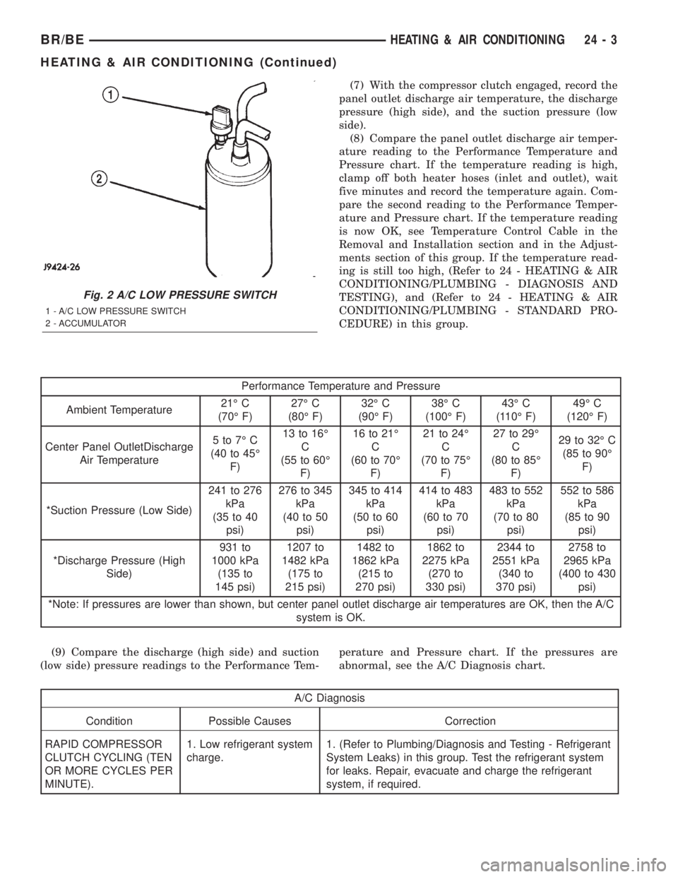
(7) With the compressor clutch engaged, record the
panel outlet discharge air temperature, the discharge
pressure (high side), and the suction pressure (low
side).
(8) Compare the panel outlet discharge air temper-
ature reading to the Performance Temperature and
Pressure chart. If the temperature reading is high,
clamp off both heater hoses (inlet and outlet), wait
five minutes and record the temperature again. Com-
pare the second reading to the Performance Temper-
ature and Pressure chart. If the temperature reading
is now OK, see Temperature Control Cable in the
Removal and Installation section and in the Adjust-
ments section of this group. If the temperature read-
ing is still too high, (Refer to 24 - HEATING & AIR
CONDITIONING/PLUMBING - DIAGNOSIS AND
TESTING), and (Refer to 24 - HEATING & AIR
CONDITIONING/PLUMBING - STANDARD PRO-
CEDURE) in this group.
Performance Temperature and Pressure
Ambient Temperature21É C
(70É F)27É C
(80É F)32É C
(90É F)38É C
(100É F)43É C
(110É F)49É C
(120É F)
Center Panel OutletDischarge
Air Temperature5to7ÉC
(40 to 45É
F)13 to 16É
C
(55 to 60É
F)16 to 21É
C
(60 to 70É
F)21 to 24É
C
(70 to 75É
F)27 to 29É
C
(80 to 85É
F)29 to 32É C
(85 to 90É
F)
*Suction Pressure (Low Side)241 to 276
kPa
(35 to 40
psi)276 to 345
kPa
(40 to 50
psi)345 to 414
kPa
(50 to 60
psi)414 to 483
kPa
(60 to 70
psi)483 to 552
kPa
(70 to 80
psi)552 to 586
kPa
(85 to 90
psi)
*Discharge Pressure (High
Side)931 to
1000 kPa
(135 to
145 psi)1207 to
1482 kPa
(175 to
215 psi)1482 to
1862 kPa
(215 to
270 psi)1862 to
2275 kPa
(270 to
330 psi)2344 to
2551 kPa
(340 to
370 psi)2758 to
2965 kPa
(400 to 430
psi)
*Note: If pressures are lower than shown, but center panel outlet discharge air temperatures are OK, then the A/C
system is OK.
(9) Compare the discharge (high side) and suction
(low side) pressure readings to the Performance Tem-perature and Pressure chart. If the pressures are
abnormal, see the A/C Diagnosis chart.
A/C Diagnosis
Condition Possible Causes Correction
RAPID COMPRESSOR
CLUTCH CYCLING (TEN
OR MORE CYCLES PER
MINUTE).1. Low refrigerant system
charge.1. (Refer to Plumbing/Diagnosis and Testing - Refrigerant
System Leaks) in this group. Test the refrigerant system
for leaks. Repair, evacuate and charge the refrigerant
system, if required.
Fig. 2 A/C LOW PRESSURE SWITCH
1 - A/C LOW PRESSURE SWITCH
2 - ACCUMULATOR
BR/BEHEATING & AIR CONDITIONING 24 - 3
HEATING & AIR CONDITIONING (Continued)
Page 2125 of 2255
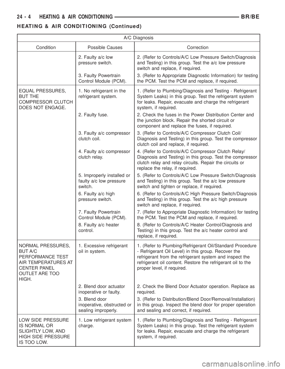
A/C Diagnosis
Condition Possible Causes Correction
2. Faulty a/c low
pressure switch.2. (Refer to Controls/A/C Low Pressure Switch/Diagnosis
and Testing) in this group. Test the a/c low pressure
switch and replace, if required.
3. Faulty Powertrain
Control Module (PCM).3. (Refer to Appropriate Diagnostic Information) for testing
the PCM. Test the PCM and replace, if required.
EQUAL PRESSURES,
BUT THE
COMPRESSOR CLUTCH
DOES NOT ENGAGE.1. No refrigerant in the
refrigerant system.1. (Refer to Plumbing/Diagnosis and Testing - Refrigerant
System Leaks) in this group. Test the refrigerant system
for leaks. Repair, evacuate and charge the refrigerant
system, if required.
2. Faulty fuse. 2. Check the fuses in the Power Distribution Center and
the junction block. Repair the shorted circuit or
component and replace the fuses, if required.
3. Faulty a/c compressor
clutch coil.3. (Refer to Controls/A/C Compressor Clutch Coil/
Diagnosis and Testing) in this group. Test the compressor
clutch coil and replace, if required.
4. Faulty a/c compressor
clutch relay.4. (Refer to Controls/A/C Compressor Clutch Relay/
Diagnosis and Testing) in this group. Test the compressor
clutch relay and relay circuits. Repair the circuits or
replace the relay, if required.
5. Improperly installed or
faulty a/c low pressure
switch.5. (Refer to Controls/A/C Low Pressure Switch/Diagnosis
and Testing) in this group. Test the a/c low pressure
switch and tighten or replace, if required.
6. Faulty a/c high
pressure switch.6. (Refer to Controls/A/C High Pressure Switch/Diagnosis
and Testing) in this group. Test the a/c high pressure
switch and replace, if required.
7. Faulty Powertrain
Control Module (PCM).7. (Refer to Appropriate Diagnostic Information) for testing
the PCM. Test the PCM and replace, if required.
8. Faulty a/c heater
control.8. (Refer to Controls/A/C Heater Control/Diagnosis and
Testing) in this group. Test the a/c heater control and
replace, if required.
NORMAL PRESSURES,
BUT A/C
PERFORMANCE TEST
AIR TEMPERATURES AT
CENTER PANEL
OUTLET ARE TOO
HIGH.1. Excessive refrigerant
oil in system.1. (Refer to Plumbing/Refrigerant Oil/Standard Procedure
- Refrigerant Oil Level) in this group. Recover the
refrigerant from the refrigerant system and inspect the
refrigerant oil content. Restore the refrigerant oil to the
proper level, if required.
2. Blend door actuator
inoperative or faulty.2. Check the Blend Door Actuator operation. Replace as
required.
3. Blend door
inoperative, obstructed or
sealing improperly.3. (Refer to Distribution/Blend Door/Removal/Installation)
in this group. Inspect the blend door for proper operation
and sealing and correct, if required.
LOW SIDE PRESSURE
IS NORMAL OR
SLIGHTLY LOW, AND
HIGH SIDE PRESSURE
IS TOO LOW.1. Low refrigerant system
charge.1. (Refer to Plumbing/Diagnosis and Testing - Refrigerant
System Leaks) in this group. Test the refrigerant system
for leaks. Repair, evacuate and charge the refrigerant
system, if required.
24 - 4 HEATING & AIR CONDITIONINGBR/BE
HEATING & AIR CONDITIONING (Continued)
Page 2126 of 2255
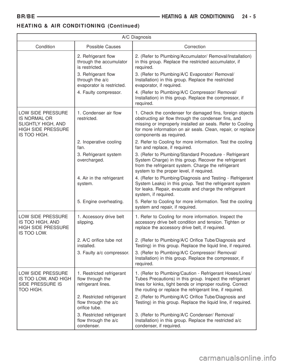
A/C Diagnosis
Condition Possible Causes Correction
2. Refrigerant flow
through the accumulator
is restricted.2. (Refer to Plumbing/Accumulator/ Removal/Installation)
in this group. Replace the restricted accumulator, if
required.
3. Refrigerant flow
through the a/c
evaporator is restricted.3. (Refer to Plumbing/A/C Evaporator/ Removal/
Installation) in this group. Replace the restricted
evaporator, if required.
4. Faulty compressor. 4. (Refer to Plumbing/A/C Compressor/ Removal/
Installation) in this group. Replace the compressor, if
required.
LOW SIDE PRESSURE
IS NORMAL OR
SLIGHTLY HIGH, AND
HIGH SIDE PRESSURE
IS TOO HIGH.1. Condenser air flow
restricted.1. Check the condenser for damaged fins, foreign objects
obstructing air flow through the condenser fins, and
missing or improperly installed air seals. Refer to Cooling
for more information on air seals. Clean, repair, or replace
components as required.
2. Inoperative cooling
fan.2. Refer to Cooling for more information. Test the cooling
fan and replace, if required.
3. Refrigerant system
overcharged.3. (Refer to Plumbing/Standard Procedure - Refrigerant
System Charge) in this group. Recover the refrigerant
from the refrigerant system. Charge the refrigerant
system to the proper level, if required.
4. Air in the refrigerant
system.4. (Refer to Plumbing/Diagnosis and Testing - Refrigerant
System Leaks) in this group. Test the refrigerant system
for leaks. Repair, evacuate and charge the refrigerant
system, if required.
5. Engine overheating. 5. Refer to Cooling for more information. Test the cooling
system and repair, if required.
LOW SIDE PRESSURE
IS TOO HIGH, AND
HIGH SIDE PRESSURE
IS TOO LOW.1. Accessory drive belt
slipping.1. Refer to Cooling for more information. Inspect the
accessory drive belt condition and tension. Tighten or
replace the accessory drive belt, if required.
2. A/C orifice tube not
installed.2. (Refer to Plumbing/A/C Orifice Tube/Diagnosis and
Testing) in this group. Replace the liquid line, if required.
3. Faulty a/c compressor. 3. (Refer to Plumbing/A/C Compressor/ Removal/
Installation) in this group. Replace the compressor, if
required.
LOW SIDE PRESSURE
IS TOO LOW, AND HIGH
SIDE PRESSURE IS
TOO HIGH.1. Restricted refrigerant
flow through the
refrigerant lines.1. (Refer to Plumbing/Caution - Refrigerant Hoses/Lines/
Tubes Precautions) in this group. Inspect the refrigerant
lines for kinks, tight bends or improper routing. Correct
the routing or replace the refrigerant line, if required.
2. Restricted refrigerant
flow through the a/c
orifice tube.2. (Refer to Plumbing/A/C Orifice Tube/Diagnosis and
Testing) in this group. Replace the liquid line, if required.
3. Restricted refrigerant
flow through the a/c
condenser.3. (Refer to Plumbing/A/C Condenser/ Removal/
Installation) in this group. Replace the restricted a/c
condenser, if required.
BR/BEHEATING & AIR CONDITIONING 24 - 5
HEATING & AIR CONDITIONING (Continued)
Page 2128 of 2255
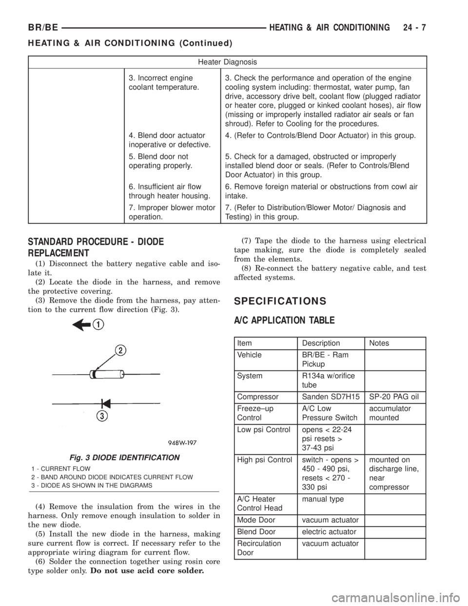
Heater Diagnosis
3. Incorrect engine
coolant temperature.3. Check the performance and operation of the engine
cooling system including: thermostat, water pump, fan
drive, accessory drive belt, coolant flow (plugged radiator
or heater core, plugged or kinked coolant hoses), air flow
(missing or improperly installed radiator air seals or fan
shroud). Refer to Cooling for the procedures.
4. Blend door actuator
inoperative or defective.4. (Refer to Controls/Blend Door Actuator) in this group.
5. Blend door not
operating properly.5. Check for a damaged, obstructed or improperly
installed blend door or seals. (Refer to Controls/Blend
Door Actuator) in this group.
6. Insufficient air flow
through heater housing.6. Remove foreign material or obstructions from cowl air
intake.
7. Improper blower motor
operation.7. (Refer to Distribution/Blower Motor/ Diagnosis and
Testing) in this group.
STANDARD PROCEDURE - DIODE
REPLACEMENT
(1) Disconnect the battery negative cable and iso-
late it.
(2) Locate the diode in the harness, and remove
the protective covering.
(3) Remove the diode from the harness, pay atten-
tion to the current flow direction (Fig. 3).
(4) Remove the insulation from the wires in the
harness. Only remove enough insulation to solder in
the new diode.
(5) Install the new diode in the harness, making
sure current flow is correct. If necessary refer to the
appropriate wiring diagram for current flow.
(6) Solder the connection together using rosin core
type solder only.Do not use acid core solder.(7) Tape the diode to the harness using electrical
tape making, sure the diode is completely sealed
from the elements.
(8) Re-connect the battery negative cable, and test
affected systems.
SPECIFICATIONS
A/C APPLICATION TABLE
Item Description Notes
Vehicle BR/BE - Ram
Pickup
System R134a w/orifice
tube
Compressor Sanden SD7H15 SP-20 PAG oil
Freeze±up
ControlA/C Low
Pressure Switchaccumulator
mounted
Low psi Control opens < 22-24
psi resets >
37-43 psi
High psi Control switch - opens >
450 - 490 psi,
resets < 270 -
330 psimounted on
discharge line,
near
compressor
A/C Heater
Control Headmanual type
Mode Door vacuum actuator
Blend Door electric actuator
Recirculation
Doorvacuum actuator
Fig. 3 DIODE IDENTIFICATION
1 - CURRENT FLOW
2 - BAND AROUND DIODE INDICATES CURRENT FLOW
3 - DIODE AS SHOWN IN THE DIAGRAMS
BR/BEHEATING & AIR CONDITIONING 24 - 7
HEATING & AIR CONDITIONING (Continued)