group 19 DODGE RAM 2002 Service Manual PDF
[x] Cancel search | Manufacturer: DODGE, Model Year: 2002, Model line: RAM, Model: DODGE RAM 2002Pages: 2255, PDF Size: 62.07 MB
Page 1321 of 2255
REMOVAL
WARNING: THE FUEL SYSTEM IS UNDER A CON-
STANT PRESSURE (EVEN WITH THE ENGINE OFF).
BEFORE SERVICING THE CHECK VALVE, FUEL
SYSTEM PRESSURE MUST BE RELEASED (GASO-
LINE POWERED ENGINES ONLY). REFER TO THE
FUEL PRESSURE RELEASE PROCEDURE IN
GROUP 14, FUEL SYSTEM.
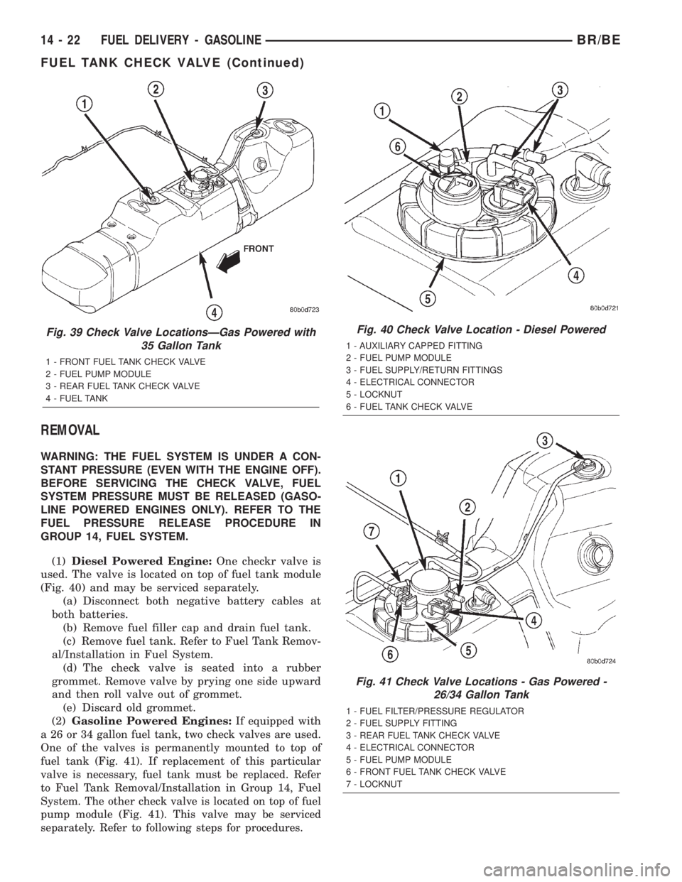
(1)Diesel Powered Engine:One checkr valve is
used. The valve is located on top of fuel tank module
(Fig. 40) and may be serviced separately.
(a) Disconnect both negative battery cables at
both batteries.
(b) Remove fuel filler cap and drain fuel tank.
(c) Remove fuel tank. Refer to Fuel Tank Remov-
al/Installation in Fuel System.
(d) The check valve is seated into a rubber
grommet. Remove valve by prying one side upward
and then roll valve out of grommet.
(e) Discard old grommet.
(2)Gasoline Powered Engines:
If equipped with
a 26 or 34 gallon fuel tank, two check valves are used.
One of the valves is permanently mounted to top of
fuel tank (Fig. 41). If replacement of this particular
valve is necessary, fuel tank must be replaced. Refer
to Fuel Tank Removal/Installation in Group 14, Fuel
System. The other check valve is located on top of fuel
pump module (Fig. 41). This valve may be serviced
separately. Refer to following steps for procedures.
Fig. 39 Check Valve LocationsÐGas Powered with
35 Gallon Tank
1 - FRONT FUEL TANK CHECK VALVE
2 - FUEL PUMP MODULE
3 - REAR FUEL TANK CHECK VALVE
4 - FUEL TANK
Fig. 40 Check Valve Location - Diesel Powered
1 - AUXILIARY CAPPED FITTING
2 - FUEL PUMP MODULE
3 - FUEL SUPPLY/RETURN FITTINGS
4 - ELECTRICAL CONNECTOR
5 - LOCKNUT
6 - FUEL TANK CHECK VALVE
Fig. 41 Check Valve Locations - Gas Powered -
26/34 Gallon Tank
1 - FUEL FILTER/PRESSURE REGULATOR
2 - FUEL SUPPLY FITTING
3 - REAR FUEL TANK CHECK VALVE
4 - ELECTRICAL CONNECTOR
5 - FUEL PUMP MODULE
6 - FRONT FUEL TANK CHECK VALVE
7 - LOCKNUT
14 - 22 FUEL DELIVERY - GASOLINEBR/BE
FUEL TANK CHECK VALVE (Continued)
Page 1322 of 2255

If equipped with a 35 gallon fuel tank, two check
valves are also used, but both valves are permanently
mounted to top of fuel tank (Fig. 42). If replacement is
necessary, fuel tank must be replaced. Refer to Fuel
Tank Removal/Installation in Group 14, Fuel System.
(a) Disconnect negative battery cable at battery.
(b) Remove fuel filler cap and drain fuel tank.
(c) Remove fuel tank. Refer to Fuel Tank Remov-
al/Installation in Fuel System.
(d) Disconnect tube (line) at valve.
(e) The check valve is seated into a rubber grom-
met. Remove valve by prying one side upward and
then roll valve out of grommet.
(f) Discard old grommet.
INSTALLATION
(1) Install new grommet into fuel pump (or fuel
tank) module.
(2) Using finger pressure only, press valve into
place.
(3) Install fuel tank. Refer to Fuel Tank Installa-
tion.
(4) Fill fuel tank. Install fuel tank filler cap.
(5) Connect negative battery cable(s).
(6) Start vehicle and check for leaks.
INLET FILTER
REMOVAL
The fuel pump inlet filter (strainer) is located on
the bottom of the fuel pump module (Fig. 43). The
fuel pump module is located inside of fuel tank.
(1) Remove fuel tank. Refer to Fuel Tank Removal/
Installation.
(2) Remove fuel pump module. Refer to Fuel Pump
Module Removal/Installation.
(3) Remove filter by carefully prying 2 lock tabs at
bottom of module with 2 screwdrivers. Filter is
snapped to module.
(4) Clean bottom of pump module.
INSTALLATION
The fuel pump inlet filter (strainer) is located on
the bottom of the fuel pump module (Fig. 43) . The
fuel pump module is located inside of fuel tank.
(1) Snap new filter to bottom of module. Be sure
o-ring is in correct position.
(2) Install fuel pump module. Refer to Fuel Pump
Module Removal/Installation.
(3) Install fuel tank. Refer to Fuel Tank Removal/
Installation.
Fig. 42 Check Valve Locations - Gas Powered with
35 Gallon Tank
1 - FRONT FUEL TANK CHECK VALVE
2 - FUEL PUMP MODULE
3 - REAR FUEL TANK CHECK VALVE
4 - FUEL TANK
Fig. 43 Fuel Pump Inlet Filter
1 - FUEL PUMP INLET FILTER
2 - LOCK TABS (2)
3 - FUEL PUMP MODULE (BOTTOM)
BR/BEFUEL DELIVERY - GASOLINE 14 - 23
FUEL TANK CHECK VALVE (Continued)
Page 1346 of 2255
(1) Raise and support the vehicle.
(2) Disconnect the wire connector from the O2S
sensor.
CAUTION: When disconnecting the sensor electrical
connector, do not pull directly on wire going into
sensor.
(3) Remove the O2S sensor with an oxygen sensor
removal and installation tool.
INSTALLATION
Threads of new oxygen sensors are factory coated
with anti-seize compound to aid in removal.DO
NOT add any additional anti-seize compound to
the threads of a new oxygen sensor.
(1) Install the O2S sensor. Tighten to 30 N´m (22
ft. lbs.) torque.
(2) Connect the O2S sensor wire connector.
(3) Lower the vehicle.
PTO SWITCH
DESCRIPTION
This Powertrain Control Module (PCM) input is
used only on models equipped with aftermarket
Power Take Off (PTO) units.
OPERATION
The input is used only to tell the PCM that the
PTO has been engaged. The PCM will disable (tem-
porarily shut down) certain OBD II diagnostic trou-
ble codes when the PTO is engaged.
When the aftermarket PTO switch has been
engaged, a 12V + signal is sent through circuit G113
to PCM pin A13. The PCM will then sense and deter-
mine that the PTO has been activated.
THROTTLE BODY
DESCRIPTION
The throttle body is located on the intake manifold.
Fuel does not enter the intake manifold through the
throttle body. Fuel is sprayed into the manifold by
the fuel injectors.
OPERATION
Filtered air from the air cleaner enters the intake
manifold through the throttle body. The throttle body
contains an air control passage controlled by an Idle
Air Control (IAC) motor. The air control passage is
used to supply air for idle conditions. A throttle valve
(plate) is used to supply air for above idle conditions.
Certain sensors are attached to the throttle body.
The accelerator pedal cable, speed control cable and
transmission control cable (when equipped) are con-
nected to the throttle body linkage arm.
A (factory adjusted) set screw is used to mechani-
cally limit the position of the throttle body throttle
plate.Never attempt to adjust the engine idle
speed using this screw.All idle speed functions are
controlled by the PCM.
REMOVAL
REMOVAL - 5.9L
A (factory adjusted) set screw is used to mechani-
cally limit the position of the throttle body throttle
plate.Never attempt to adjust the engine idle
speed using this screw.All idle speed functions are
controlled by the powertrain control module (PCM).
(1) Remove the air cleaner.
(2) Disconnect throttle body electrical connectors
at MAP sensor, IAC motor and TPS (Fig. 40).
(3) Remove vacuum line at throttle body.
(4) Remove all control cables from throttle body
(lever) arm. Refer to the Accelerator Pedal and Throt-
tle Cable section of this group for additional informa-
tion.
(5) Remove four throttle body mounting bolts (Fig.
41).
(6) Remove throttle body from intake manifold.
(7) Discard old throttle body-to-intake manifold
gasket.
REMOVAL - 8.0L
A (factory adjusted) set screw is used to mechani-
cally limit the position of the throttle body throttle
plate.Never attempt to adjust the engine idle
speed using this screw.All idle speed functions are
controlled by the powertrain control module (PCM).
(1) Remove the air cleaner cover.
Fig. 39 Oxygen SensorsÐ5.9L California Engines
BR/BEFUEL INJECTION - GASOLINE 14 - 47
O2 SENSOR (Continued)
Page 1347 of 2255
(2) Remove the 4 air cleaner housing mounting
nuts and remove housing from throttle body.
(3) Disconnect throttle body electrical connectors
at the IAC motor and TPS.
(4) Remove all control cables from throttle body
(lever) arm. Refer to the Accelerator Pedal and Throt-tle Cable section of this group for additional informa-
tion.
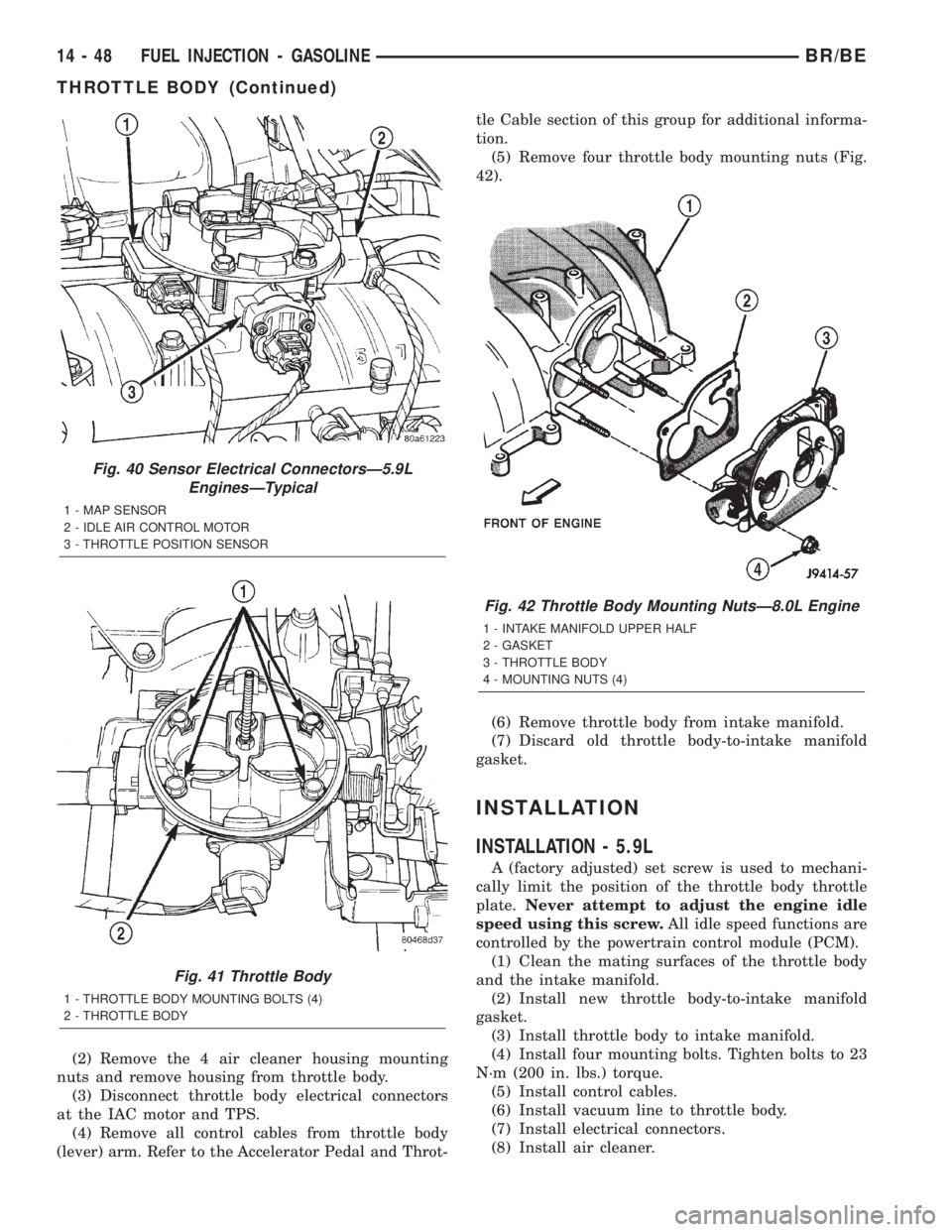
(5) Remove four throttle body mounting nuts (Fig.
42).
(6) Remove throttle body from intake manifold.
(7) Discard old throttle body-to-intake manifold
gasket.
INSTALLATION
INSTALLATION - 5.9L
A (factory adjusted) set screw is used to mechani-
cally limit the position of the throttle body throttle
plate.Never attempt to adjust the engine idle
speed using this screw.All idle speed functions are
controlled by the powertrain control module (PCM).
(1) Clean the mating surfaces of the throttle body
and the intake manifold.
(2) Install new throttle body-to-intake manifold
gasket.
(3) Install throttle body to intake manifold.
(4) Install four mounting bolts. Tighten bolts to 23
N´m (200 in. lbs.) torque.
(5) Install control cables.
(6) Install vacuum line to throttle body.
(7) Install electrical connectors.
(8) Install air cleaner.
Fig. 40 Sensor Electrical ConnectorsÐ5.9L
EnginesÐTypical
1 - MAP SENSOR
2 - IDLE AIR CONTROL MOTOR
3 - THROTTLE POSITION SENSOR
Fig. 41 Throttle Body
1 - THROTTLE BODY MOUNTING BOLTS (4)
2 - THROTTLE BODY
Fig. 42 Throttle Body Mounting NutsÐ8.0L Engine
1 - INTAKE MANIFOLD UPPER HALF
2 - GASKET
3 - THROTTLE BODY
4 - MOUNTING NUTS (4)
14 - 48 FUEL INJECTION - GASOLINEBR/BE
THROTTLE BODY (Continued)
Page 1371 of 2255
(1) Remove hose clamp and crankcase vent hose at
crankcase breather (Fig. 26). Remove crankcase
breather from gear cover. Breather threads into
cover.
(2) Remove injection pump nut and washer (Fig.
27). Locate keyway behind washer.
(3) Be sure keyway aligning fuel injection pump
shaft to injection pump gear is in proper position and
pump gear has not slipped on pump shaft.
The following steps will require removing timing
gear cover to gain access to timing gears. Refer to
Group 9, Engines for procedures.
(4) Use a T-type puller to separate injection pump
gear from pump shaft.
(5) Be sure keyway has been installed with arrow
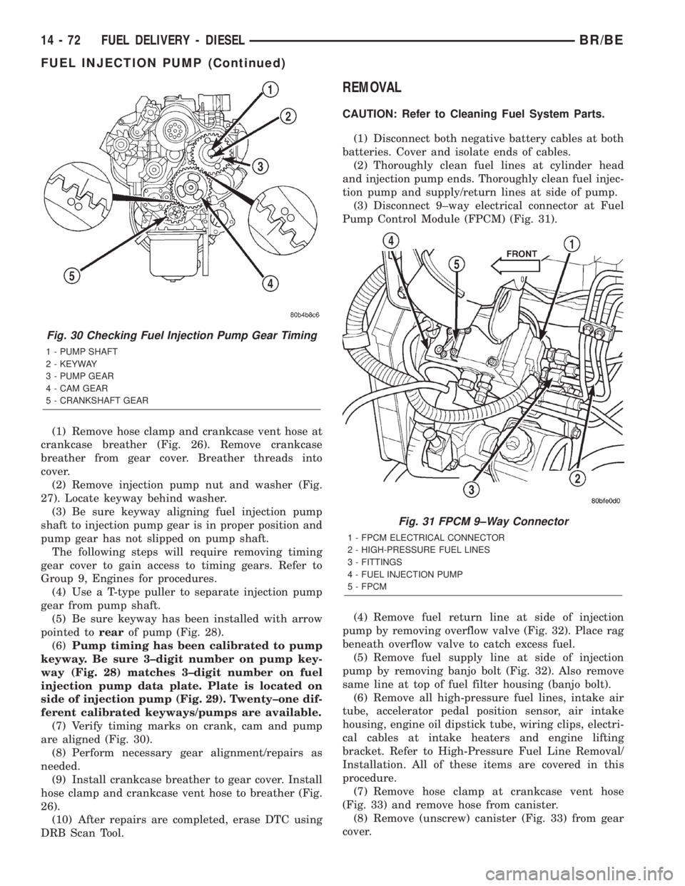
pointed torearof pump (Fig. 28).
(6)Pump timing has been calibrated to pump
keyway. Be sure 3±digit number on pump key-
way (Fig. 28) matches 3±digit number on fuel
injection pump data plate. Plate is located on
side of injection pump (Fig. 29). Twenty±one dif-
ferent calibrated keyways/pumps are available.
(7) Verify timing marks on crank, cam and pump
are aligned (Fig. 30).
(8) Perform necessary gear alignment/repairs as
needed.
(9) Install crankcase breather to gear cover. Install
hose clamp and crankcase vent hose to breather (Fig.
26).
(10) After repairs are completed, erase DTC using
DRB Scan Tool.
REMOVAL
CAUTION: Refer to Cleaning Fuel System Parts.
(1) Disconnect both negative battery cables at both
batteries. Cover and isolate ends of cables.
(2) Thoroughly clean fuel lines at cylinder head
and injection pump ends. Thoroughly clean fuel injec-
tion pump and supply/return lines at side of pump.
(3) Disconnect 9±way electrical connector at Fuel
Pump Control Module (FPCM) (Fig. 31).
(4) Remove fuel return line at side of injection
pump by removing overflow valve (Fig. 32). Place rag
beneath overflow valve to catch excess fuel.
(5) Remove fuel supply line at side of injection
pump by removing banjo bolt (Fig. 32). Also remove
same line at top of fuel filter housing (banjo bolt).
(6) Remove all high-pressure fuel lines, intake air
tube, accelerator pedal position sensor, air intake
housing, engine oil dipstick tube, wiring clips, electri-
cal cables at intake heaters and engine lifting
bracket. Refer to High-Pressure Fuel Line Removal/
Installation. All of these items are covered in this
procedure.
(7) Remove hose clamp at crankcase vent hose
(Fig. 33) and remove hose from canister.
(8) Remove (unscrew) canister (Fig. 33) from gear
cover.
Fig. 30 Checking Fuel Injection Pump Gear Timing
1 - PUMP SHAFT
2 - KEYWAY
3 - PUMP GEAR
4 - CAM GEAR
5 - CRANKSHAFT GEAR
Fig. 31 FPCM 9±Way Connector
1 - FPCM ELECTRICAL CONNECTOR
2 - HIGH-PRESSURE FUEL LINES
3 - FITTINGS
4 - FUEL INJECTION PUMP
5 - FPCM
14 - 72 FUEL DELIVERY - DIESELBR/BE
FUEL INJECTION PUMP (Continued)
Page 1377 of 2255
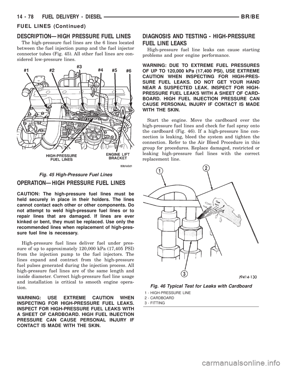
DESCRIPTIONÐHIGH PRESSURE FUEL LINES
The high-pressure fuel lines are the 6 lines located
between the fuel injection pump and the fuel injector
connector tubes (Fig. 45). All other fuel lines are con-
sidered low-pressure lines.
OPERATIONÐHIGH PRESSURE FUEL LINES
CAUTION: The high-pressure fuel lines must be
held securely in place in their holders. The lines
cannot contact each other or other components. Do
not attempt to weld high-pressure fuel lines or to
repair lines that are damaged. If lines are ever
kinked or bent, they must be replaced. Use only the
recommended lines when replacement of high-pres-
sure fuel line is necessary.
High-pressure fuel lines deliver fuel under pres-
sure of up to approximately 120,000 kPa (17,405 PSI)
from the injection pump to the fuel injectors. The
lines expand and contract from the high-pressure
fuel pulses generated during the injection process. All
high-pressure fuel lines are of the same length and
inside diameter. Correct high-pressure fuel line usage
and installation is critical to smooth engine opera-
tion.
WARNING: USE EXTREME CAUTION WHEN
INSPECTING FOR HIGH-PRESSURE FUEL LEAKS.
INSPECT FOR HIGH-PRESSURE FUEL LEAKS WITH
A SHEET OF CARDBOARD. HIGH FUEL INJECTION
PRESSURE CAN CAUSE PERSONAL INJURY IF
CONTACT IS MADE WITH THE SKIN.
DIAGNOSIS AND TESTING - HIGH-PRESSURE
FUEL LINE LEAKS
High-pressure fuel line leaks can cause starting
problems and poor engine performance.
WARNING: DUE TO EXTREME FUEL PRESSURES
OF UP TO 120,000 kPa (17,400 PSI), USE EXTREME
CAUTION WHEN INSPECTING FOR HIGH-PRES-
SURE FUEL LEAKS. DO NOT GET YOUR HAND
NEAR A SUSPECTED LEAK. INSPECT FOR HIGH-
PRESSURE FUEL LEAKS WITH A SHEET OF CARD-
BOARD. HIGH FUEL INJECTION PRESSURE CAN
CAUSE PERSONAL INJURY IF CONTACT IS MADE
WITH THE SKIN.
Start the engine. Move the cardboard over the
high-pressure fuel lines and check for fuel spray onto
the cardboard (Fig. 46). If a high-pressure line con-
nection is leaking, bleed the system and tighten the
connection. Refer to the Air Bleed Procedure in this
group for procedures. Replace damaged, restricted or
leaking high-pressure fuel lines with the correct
replacement line.
Fig. 45 High-Pressure Fuel Lines
Fig. 46 Typical Test for Leaks with Cardboard
1 - HIGH-PRESSURE LINE
2 - CARDBOARD
3 - FITTING
14 - 78 FUEL DELIVERY - DIESELBR/BE
FUEL LINES (Continued)
Page 1389 of 2255
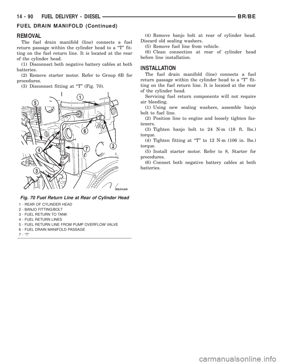
REMOVAL
The fuel drain manifold (line) connects a fuel
return passage within the cylinder head to a ªTº fit-
ting on the fuel return line. It is located at the rear
of the cylinder head.
(1) Disconnect both negative battery cables at both
batteries.
(2) Remove starter motor. Refer to Group 8B for
procedures.
(3) Disconnect fitting at ªTº (Fig. 70).(4) Remove banjo bolt at rear of cylinder head.
Discard old sealing washers.
(5) Remove fuel line from vehicle.
(6) Clean connection at rear of cylinder head
before line installation.
INSTALLATION
The fuel drain manifold (line) connects a fuel
return passage within the cylinder head to a ªTº fit-
ting on the fuel return line. It is located at the rear
of the cylinder head.
Servicing fuel return components will not require
air bleeding.
(1) Using new sealing washers, assemble banjo
bolt to fuel line.
(2) Position line to engine and loosely tighten fas-
teners.
(3) Tighten banjo bolt to 24 N´m (18 ft. lbs.)
torque.
(4) Tighten fitting at ªTº to 12 N´m (106 in. lbs.)
torque.
(5) Install starter motor. Refer to 8, Starter for
procedures.
(6) Connect both negative battery cables at both
batteries.
Fig. 70 Fuel Return Line at Rear of Cylinder Head
1 - REAR OF CYLINDER HEAD
2 - BANJO FITTING/BOLT
3 - FUEL RETURN TO TANK
4 - FUEL RETURN LINES
5 - FUEL RETURN LINE FROM PUMP OVERFLOW VALVE
6 - FUEL DRAIN MANIFOLD PASSAGE
7 - ªTº
14 - 90 FUEL DELIVERY - DIESELBR/BE
FUEL DRAIN MANIFOLD (Continued)
Page 1396 of 2255
(1) Disconnect both negative battery cables at both
batteries.
(2) Remove cable cover (Fig. 6). Cable cover is
attached with 2 Phillips screws, 2 plastic retention
clips and 2 push tabs (Fig. 6). Remove 2 Phillips
screws and carefully pry out 2 retention clips. After
clip removal, push rearward on front tab, and
upward on lower tab for cover removal.
(3) Using finger pressure only, disconnect end of
speed control servo cable from throttle lever pin by
pulling forward on connector while holding lever
rearward (Fig. 7).DO NOT try to pull connector
off perpendicular to lever pin. Connector will
be broken.
(4) Using two small screwdrivers, pry throttle
cable connector socket from throttle lever ball (Fig.
7).Be very careful not to bend throttle lever
arm.
(5) Disconnect transmission control cable at lever
arm (if equipped). Refer to 21, Transmission.
(6) Squeeze pinch tabs on speed control cable (Fig.
7) and pull cable rearward to remove from cable
mounting bracket.
(7) Squeeze pinch tabs on throttle cable (Fig. 7)
and pull cable rearward to remove from cable mount-
ing bracket.
(8) If equipped with an automatic transmission,
refer to 21, Transmission for transmission control
cable removal procedures.
(9) Disconnect wiring harness clip (Fig. 8) at bot-
tom of bracket.
(10) Remove 6 mounting bolts (Fig. 8) and par-
tially remove APPS assembly from engine. After
assembly is partially removed, disconnect electrical
connector from bottom of sensor by pushing on con-
nector tab (Fig. 9).
(11) Remove APPS assembly from engine.
INSTALLATION
The APPS is serviced (replaced) as one assembly
including the lever, brackets and sensor. The APPS is
calibrated to its mounting bracket. The APPS assem-
bly is located at left-front of engine below plastic
cable/lever/linkage cover (Fig. 6) .
(1) Snap electrical connector into bottom of sensor.
(2) Position APPS assembly to engine and install 6
bolts. Tighten bolts to 12 N´m (105 in. lbs.) torque.
(3) Connect wiring harness clip (Fig. 8) at bottom
of bracket.
(4) If equipped with an automatic transmission,
refer to Group 21, Transmission for transmission con-
trol cable installation procedures.
(5) Install speed control cable into mounting
bracket. Be sure pinch tabs (Fig. 7) have secured
cable.(6) Install throttle cable into mounting bracket. Be
sure pinch tabs (Fig. 7) have secured cable.
(7) Connect throttle cable at lever (snaps on).
(8) Connect speed control cable to lever by pushing
cable connector rearward onto lever pin while hold-
ing lever forward.
(9) Install cable cover.
(10) Connect both negative battery cables to both
batteries.
(11)ECM Calibration:Turn key to ON position.
Without starting engine, slowly press throttle pedal
to floor and then slowly release. This step must be
done (one time) to ensure accelerator pedal position
sensor calibration has been learned by ECM. If not
done, possible DTC's may be set.
(12) Use DRB scan tool to erase any DTC's from
ECM/PCM.
FUEL INJECTOR
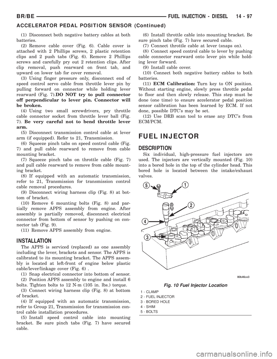
DESCRIPTION
Six individual, high-pressure fuel injectors are
used. The injectors are vertically mounted (Fig. 10)
into a bored hole in the top of the cylinder head. This
bored hole is located between the intake/exhaust
valves.
Fig. 10 Fuel Injector Location
1 - CLAMP
2 - FUEL INJECTOR
3 - BORED HOLE
4 - SHIM
5 - BOLTS
BR/BEFUEL INJECTION - DIESEL 14 - 97
ACCELERATOR PEDAL POSITION SENSOR (Continued)
Page 1452 of 2255
(6) Mark the pitman arm and shaft positions for
installation reference. Remove the nut and washer
from the pitman arm. Remove the pitman arm with
Puller C-4150A.
INSTALLATION
(1) Align reference marks and install pitman arm.
(2) Install the lock washer and retaining nut on
the pitman shaft and tighten nut to 251 N´m (185 ft.
lbs.).
(3) Install drag link to the pitman arm. Install the
nut and tighten to 108 N´m (80 ft. lbs.).
(4) Install drag link to the right steering knuckle.
Install the nut and tighten to 88 N´m (65 ft. lbs.).
(5) Install tie rod to the left steering knuckle and
drag link. Install the nuts and tighten to 108 N´m
(80 ft. lbs.).(6) Install steering damper on the axle. Tighten
nut to 95 N´m (75 ft. lbs.).
(7) Install steering damper on the tie rod. Tighten
nut to 81 N´m (60 ft. lbs.).
(8) Remove the supports and lower the vehicle to
the surface. Center steering wheel and adjust toe,
refer to Group 2 Suspension.
(9) After adjustment tighten tie rod adjustment
sleeve clamp bolts to 61 N´m (45 ft. lbs.).
NOTE: Position the clamp on the sleeve so retain-
ing bolt is located on the bottom side of the sleeve.
SPECIFICATIONS
TORQUE CHART
TORQUE SPECIFICATIONS
DESCRIPTION N´m Ft. Lbs. In. Lbs.
Pitman Arm
Gear Shaft251 185 Ð
Drag Link
Pitman Arm108 80 Ð
Drag Link
Tie Rod88 65 Ð
Drag Link
Adjuster Clamp61 45 Ð
Tie Rod End
Knuckle108 80 Ð
Tie Rod End
Adjuster Clamp61 45 Ð
Steering Damper
Axle95 70 Ð
Steering Damper
Tie Rod81 60 Ð
BR/BELINKAGE - 4WD 19 - 43
LINKAGE - 4WD (Continued)
Page 1555 of 2255
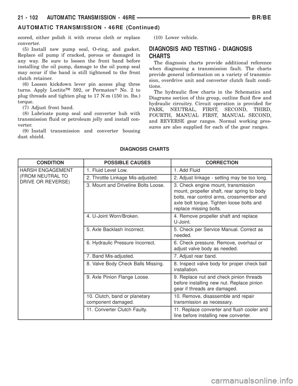
scored, either polish it with crocus cloth or replace
converter.
(5) Install new pump seal, O-ring, and gasket.
Replace oil pump if cracked, porous or damaged in
any way. Be sure to loosen the front band before
installing the oil pump, damage to the oil pump seal
may occur if the band is still tightened to the front
clutch retainer.
(6) Loosen kickdown lever pin access plug three
turns. Apply LoctiteŸ 592, or PermatextNo.2to
plug threads and tighten plug to 17 N´m (150 in. lbs.)
torque.
(7) Adjust front band.
(8) Lubricate pump seal and converter hub with
transmission fluid or petroleum jelly and install con-
verter.
(9) Install transmission and converter housing
dust shield.(10) Lower vehicle.
DIAGNOSIS AND TESTING - DIAGNOSIS
CHARTS
The diagnosis charts provide additional reference
when diagnosing a transmission fault. The charts
provide general information on a variety of transmis-
sion, overdrive unit and converter clutch fault condi-
tions.
The hydraulic flow charts in the Schematics and
Diagrams section of this group, outline fluid flow and
hydraulic circuitry. Circuit operation is provided for
PARK, NEUTRAL, FIRST, SECOND, THIRD,
FOURTH, MANUAL FIRST, MANUAL SECOND,
and REVERSE gear ranges. Normal working pres-
sures are also supplied for each of the gear ranges.
DIAGNOSIS CHARTS
CONDITION POSSIBLE CAUSES CORRECTION
HARSH ENGAGEMENT
(FROM NEUTRAL TO
DRIVE OR REVERSE)1. Fluid Level Low. 1. Add Fluid
2. Throttle Linkage Mis-adjusted. 2. Adjust linkage - setting may be too long.
3. Mount and Driveline Bolts Loose. 3. Check engine mount, transmission
mount, propeller shaft, rear spring to body
bolts, rear control arms, crossmember and
axle bolt torque. Tighten loose bolts and
replace missing bolts.
4. U-Joint Worn/Broken. 4. Remove propeller shaft and replace
U-Joint.
5. Axle Backlash Incorrect. 5. Check per Service Manual. Correct as
needed.
6. Hydraulic Pressure Incorrect. 6. Check pressure. Remove, overhaul or
adjust valve body as needed.
7. Band Mis-adjusted. 7. Adjust rear band.
8. Valve Body Check Balls Missing. 8. Inspect valve body for proper check ball
installation.
9. Axle Pinion Flange Loose. 9. Replace nut and check pinion threads
before installing new nut. Replace pinion
gear if threads are damaged.
10. Clutch, band or planetary
component damaged.10. Remove, disassemble and repair
transmission as necessary.
11. Converter Clutch Faulty. 11. Replace converter and flush cooler and
line before installing new converter.
21 - 102 AUTOMATIC TRANSMISSION - 46REBR/BE
AUTOMATIC TRANSMISSION - 46RE (Continued)