manual transmission DODGE RAM 2002 Service Service Manual
[x] Cancel search | Manufacturer: DODGE, Model Year: 2002, Model line: RAM, Model: DODGE RAM 2002Pages: 2255, PDF Size: 62.07 MB
Page 1249 of 2255
INSTALLATION
(1) With engine raised SLIGHTLY, position the
engine mount to the block. Install the bolts and
tighten to 149 N´m (110 ft. lbs.) torque.
(2) Install the thru-bolt into the engine mount.
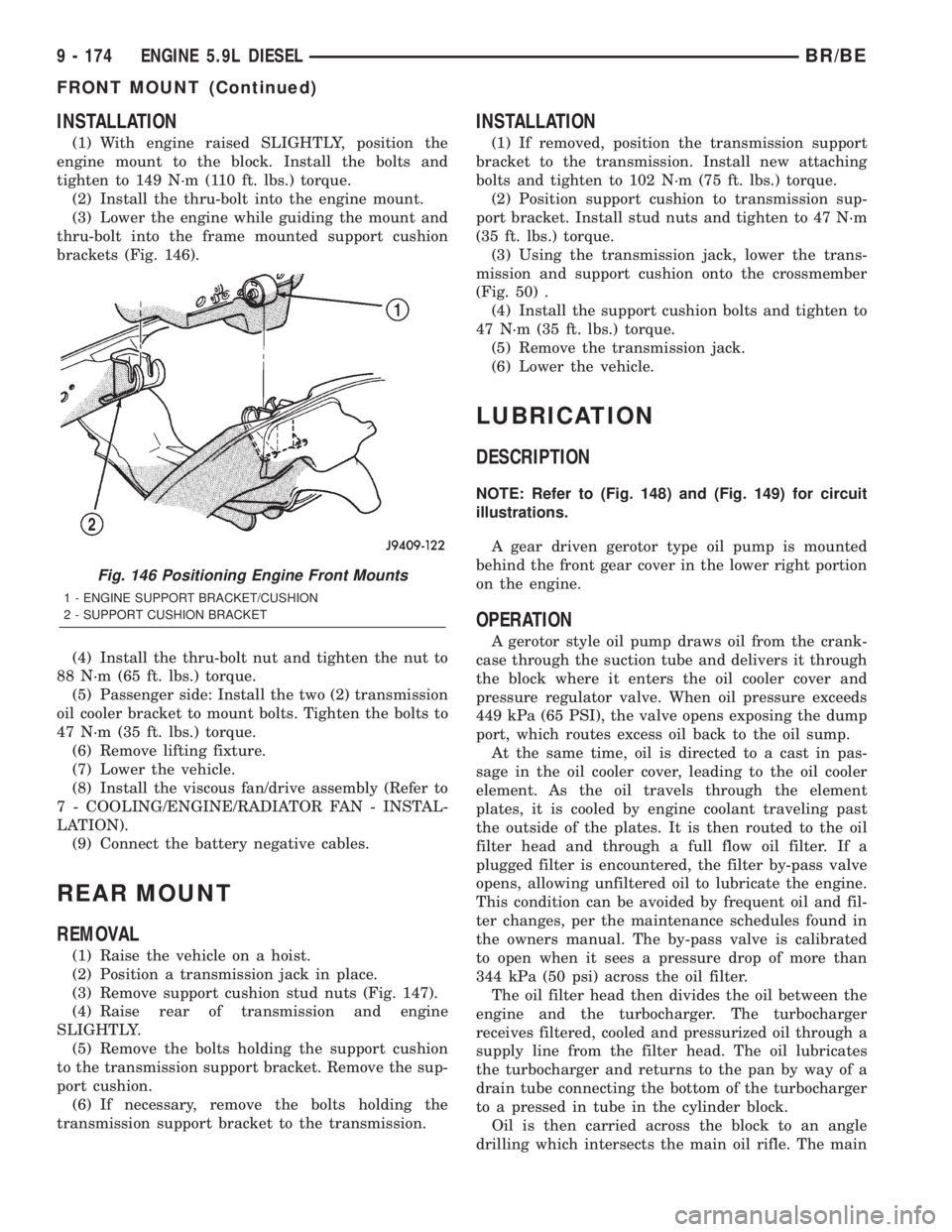
(3) Lower the engine while guiding the mount and
thru-bolt into the frame mounted support cushion
brackets (Fig. 146).
(4) Install the thru-bolt nut and tighten the nut to
88 N´m (65 ft. lbs.) torque.
(5) Passenger side: Install the two (2) transmission
oil cooler bracket to mount bolts. Tighten the bolts to
47 N´m (35 ft. lbs.) torque.
(6) Remove lifting fixture.
(7) Lower the vehicle.
(8) Install the viscous fan/drive assembly (Refer to
7 - COOLING/ENGINE/RADIATOR FAN - INSTAL-
LATION).
(9) Connect the battery negative cables.
REAR MOUNT
REMOVAL
(1) Raise the vehicle on a hoist.
(2) Position a transmission jack in place.
(3) Remove support cushion stud nuts (Fig. 147).
(4) Raise rear of transmission and engine
SLIGHTLY.
(5) Remove the bolts holding the support cushion
to the transmission support bracket. Remove the sup-
port cushion.
(6) If necessary, remove the bolts holding the
transmission support bracket to the transmission.
INSTALLATION
(1) If removed, position the transmission support
bracket to the transmission. Install new attaching
bolts and tighten to 102 N´m (75 ft. lbs.) torque.
(2) Position support cushion to transmission sup-
port bracket. Install stud nuts and tighten to 47 N´m
(35 ft. lbs.) torque.
(3) Using the transmission jack, lower the trans-
mission and support cushion onto the crossmember
(Fig. 50) .
(4) Install the support cushion bolts and tighten to
47 N´m (35 ft. lbs.) torque.
(5) Remove the transmission jack.
(6) Lower the vehicle.
LUBRICATION
DESCRIPTION
NOTE: Refer to (Fig. 148) and (Fig. 149) for circuit
illustrations.
A gear driven gerotor type oil pump is mounted
behind the front gear cover in the lower right portion
on the engine.
OPERATION
A gerotor style oil pump draws oil from the crank-
case through the suction tube and delivers it through
the block where it enters the oil cooler cover and
pressure regulator valve. When oil pressure exceeds
449 kPa (65 PSI), the valve opens exposing the dump
port, which routes excess oil back to the oil sump.
At the same time, oil is directed to a cast in pas-
sage in the oil cooler cover, leading to the oil cooler
element. As the oil travels through the element
plates, it is cooled by engine coolant traveling past
the outside of the plates. It is then routed to the oil
filter head and through a full flow oil filter. If a
plugged filter is encountered, the filter by-pass valve
opens, allowing unfiltered oil to lubricate the engine.
This condition can be avoided by frequent oil and fil-
ter changes, per the maintenance schedules found in
the owners manual. The by-pass valve is calibrated
to open when it sees a pressure drop of more than
344 kPa (50 psi) across the oil filter.
The oil filter head then divides the oil between the
engine and the turbocharger. The turbocharger
receives filtered, cooled and pressurized oil through a
supply line from the filter head. The oil lubricates
the turbocharger and returns to the pan by way of a
drain tube connecting the bottom of the turbocharger
to a pressed in tube in the cylinder block.
Oil is then carried across the block to an angle
drilling which intersects the main oil rifle. The main
Fig. 146 Positioning Engine Front Mounts
1 - ENGINE SUPPORT BRACKET/CUSHION
2 - SUPPORT CUSHION BRACKET
9 - 174 ENGINE 5.9L DIESELBR/BE
FRONT MOUNT (Continued)
Page 1331 of 2255
(29) Inspect transmission torque convertor housing
(automatic transmission) or clutch housing (manual
transmission) for damage to timing ring on drive
plate/flywheel.
(30) Verify that battery cable and solenoid feed
wire connections to the starter solenoid are tight and
clean. Inspect for chaffed wires or wires rubbing up
against other components.
VISUAL INSPECTIONÐ8.0L ENGINE
A visual inspection for loose, disconnected or incor-
rectly routed wires and hoses should be made. This
should be done before attempting to diagnose or ser-
vice the fuel injection system. A visual check will
help spot these faults and save unnecessary test and
diagnostic time. A thorough visual inspection will
include the following checks:
(1) Verify that the three 32±way electrical connec-
tors are fully inserted into the connector of the pow-
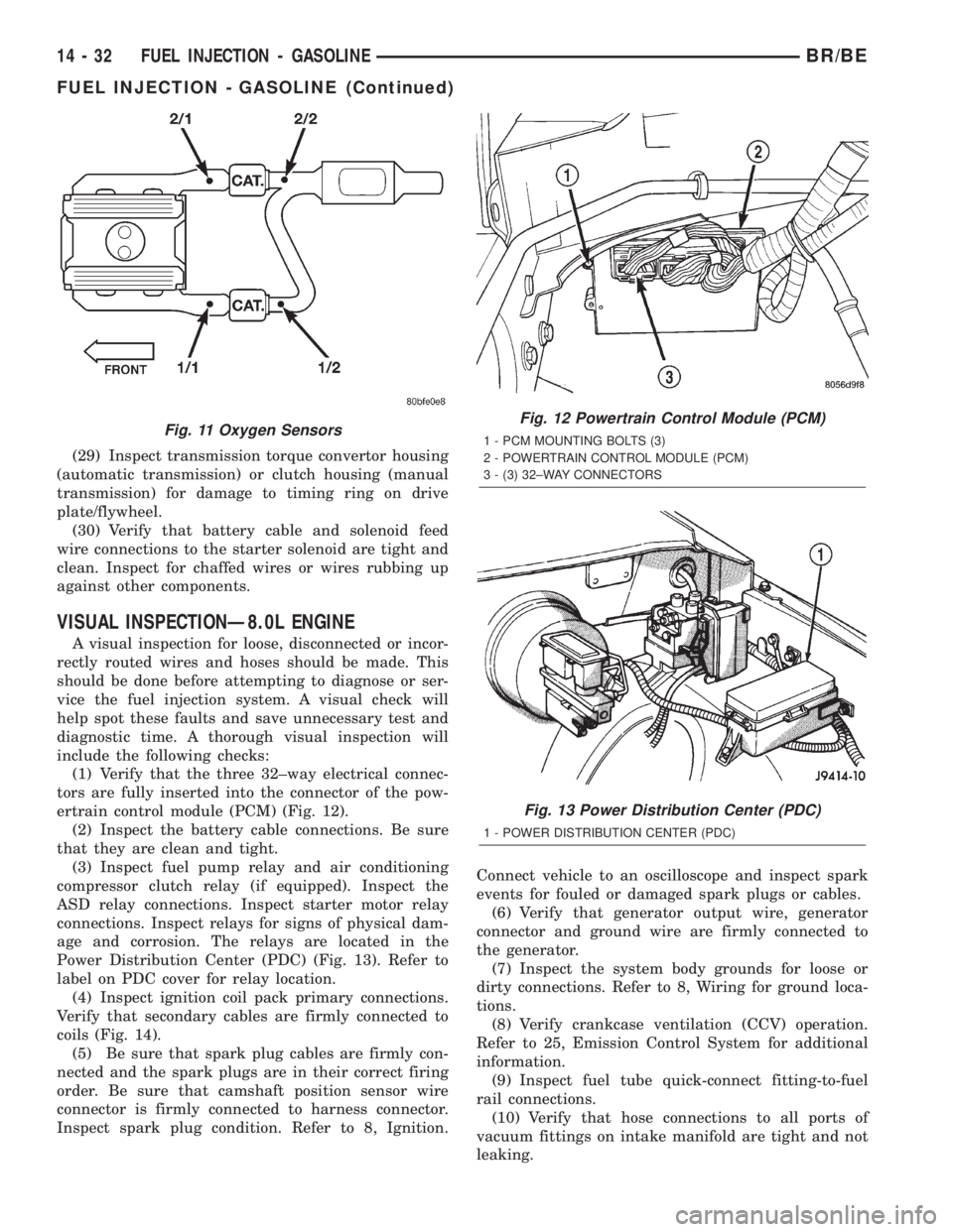
ertrain control module (PCM) (Fig. 12).
(2) Inspect the battery cable connections. Be sure
that they are clean and tight.
(3) Inspect fuel pump relay and air conditioning
compressor clutch relay (if equipped). Inspect the
ASD relay connections. Inspect starter motor relay
connections. Inspect relays for signs of physical dam-
age and corrosion. The relays are located in the
Power Distribution Center (PDC) (Fig. 13). Refer to
label on PDC cover for relay location.
(4) Inspect ignition coil pack primary connections.
Verify that secondary cables are firmly connected to
coils (Fig. 14).
(5) Be sure that spark plug cables are firmly con-
nected and the spark plugs are in their correct firing
order. Be sure that camshaft position sensor wire
connector is firmly connected to harness connector.
Inspect spark plug condition. Refer to 8, Ignition.Connect vehicle to an oscilloscope and inspect spark
events for fouled or damaged spark plugs or cables.
(6) Verify that generator output wire, generator
connector and ground wire are firmly connected to
the generator.
(7) Inspect the system body grounds for loose or
dirty connections. Refer to 8, Wiring for ground loca-
tions.
(8) Verify crankcase ventilation (CCV) operation.
Refer to 25, Emission Control System for additional
information.
(9) Inspect fuel tube quick-connect fitting-to-fuel
rail connections.
(10) Verify that hose connections to all ports of
vacuum fittings on intake manifold are tight and not
leaking.
Fig. 11 Oxygen SensorsFig. 12 Powertrain Control Module (PCM)
1 - PCM MOUNTING BOLTS (3)
2 - POWERTRAIN CONTROL MODULE (PCM)
3 - (3) 32±WAY CONNECTORS
Fig. 13 Power Distribution Center (PDC)
1 - POWER DISTRIBUTION CENTER (PDC)
14 - 32 FUEL INJECTION - GASOLINEBR/BE
FUEL INJECTION - GASOLINE (Continued)
Page 1333 of 2255
(20) Raise and support the vehicle.
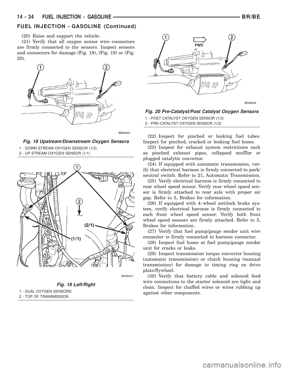
(21) Verify that all oxygen sensor wire connectors
are firmly connected to the sensors. Inspect sensors
and connectors for damage (Fig. 18), (Fig. 19) or (Fig.
20).
(22) Inspect for pinched or leaking fuel tubes.
Inspect for pinched, cracked or leaking fuel hoses.
(23) Inspect for exhaust system restrictions such
as pinched exhaust pipes, collapsed muffler or
plugged catalytic convertor.
(24) If equipped with automatic transmission, ver-
ify that electrical harness is firmly connected to park/
neutral switch. Refer to 21, Automatic Transmission.
(25) Verify electrical harness is firmly connected to
rear wheel speed sensor. Verify rear wheel speed sen-
sor is firmly attached to rear axle with proper air
gap. Refer to 5, Brakes for information.
(26) If equipped with 4±wheel antilock brake sys-
tem, verify electrical harness is firmly connected to
each front wheel speed sensor. Verify both front
wheel speed sensors are firmly attached. Refer to 5,
Brakes for information.
(27) Verify that fuel pump/gauge sender unit wire
connector is firmly connected to harness connector.
(28) Inspect fuel hoses at fuel pump/gauge sender
unit for cracks or leaks.
(29) Inspect transmission torque convertor housing
(automatic transmission) or clutch housing (manual
transmission) for damage to timing ring on drive
plate/flywheel.
(30) Verify that battery cable and solenoid feed
wire connections to the starter solenoid are tight and
clean. Inspect for chaffed wires or wires rubbing up
against other components.
Fig. 18 Upstream/Downstream Oxygen Sensors
1 - DOWN STREAM OXYGEN SENSOR (1/2)
2 - UP STREAM OXYGEN SENSOR (1/1)
Fig. 19 Left/Right
1 - DUAL OXYGEN SENSORS
2 - TOP OF TRANSMISSION
Fig. 20 Pre-Catalyst/Post Catalyst Oxygen Sensors
1 - POST CATALYST OXYGEN SENSOR (1/3)
2 - PRE-CATALYST OXYGEN SENSOR (1/2)
14 - 34 FUEL INJECTION - GASOLINEBR/BE
FUEL INJECTION - GASOLINE (Continued)
Page 1419 of 2255
MECHANICAL DIAGNOSIS (KEY DIFFICULT TO
ROTATE)
Vehicles equipped with an automatic trans-
mission and a floor mounted shifter:a cable is
used to connect the interlock device in the steering
column assembly, to the transmission floor shift
lever. This interlock device is used to lock the trans-
mission shifter in the PARK position when the key
lock cylinder is rotated to the LOCKED or ACCES-
SORY position. The interlock device within the steer-
ing column is not serviceable. If repair is necessary,
the steering column assembly must be replaced.
(Refer to 19 - STEERING/COLUMN - REMOVAL).
If the ignition key is difficult to rotate to or from
the LOCK or ACCESSORY position, it may not be
the fault of the key cylinder or the steering column
components. The brake transmission shift interlock
cable may be out of adjustment. Refer to Brake
Transmission Shift Interlock Cable Adjustment in
Transmissions for adjustment procedures.
Vehicles equipped with an automatic trans-
mission and a steering column mounted shifter:
an interlock device is located within the steering col-
umn. This interlock device is used to lock the trans-
mission shifter in the PARK position when the key
lock cylinder is in the LOCKED or ACCESSORY
position. If it is difficult to rotate the key to or from
the LOCK or ACCESSORY position, the interlock
device within the steering column may be defective.
This device is not serviceable. If repair is necessary,
the steering column assembly must be replaced.
(Refer to 19 - STEERING/COLUMN - REMOVAL).
Vehicles equipped with a manual transmis-
sion and a floor mounted shifter:on certain mod-
els, a lever is located on the steering column behind
the ignition key lock cylinder. The lever must be
manually operated to allow rotation of the ignition
key lock cylinder to the LOCK or ACCESSORY posi-
tion. If it is difficult to rotate the key to the LOCK or
ACCESSORY position, the lever mechanism may be
defective. This mechanism is not serviceable. If
repair is necessary, the steering column assembly
must be replaced. (Refer to 19 - STEERING/COL-
UMN - REMOVAL).
On other models, the ignition key cylinder must be
depressed to allow it to be rotated into the LOCK or
ACCESSORY position. If it is difficult to rotate the
key to the LOCK or ACCESSORY position, the lock
mechanism within the steering column may be defec-
tive. This mechanism is not serviceable. If repair is
necessary, the steering column assembly must be
replaced. (Refer to 19 - STEERING/COLUMN -
REMOVAL).
LOCK CYLINDER
REMOVAL
The ignition key must be in the key cylinder for
cylinder removal.
(1) Disconnect negative cable from battery.
(2) If equipped with tilt column, remove tilt lever
by turning it counterclockwise.
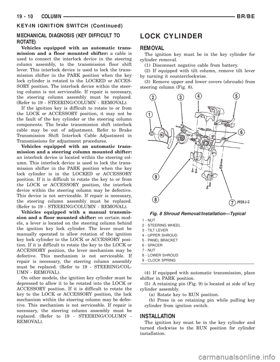
(3) Remove upper and lower covers (shrouds) from
steering column (Fig. 8).
(4) If equipped with automatic transmission, place
shifter in PARK position.
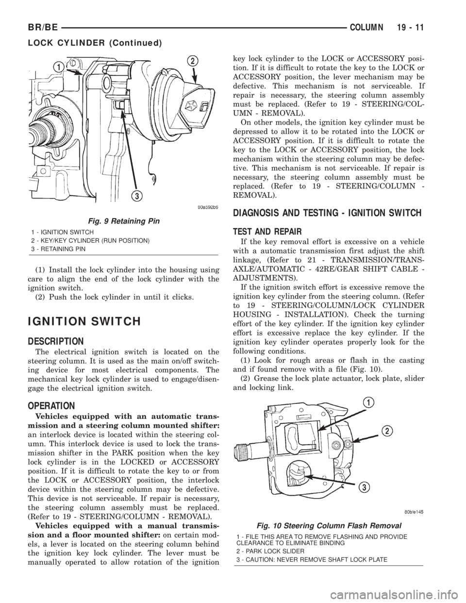
(5) A retaining pin (Fig. 9) is located at side of key
cylinder assembly.
(a) Rotate key to RUN position.
(b) Press in on retaining pin while pulling key
cylinder from ignition switch.
INSTALLATION
The ignition key must be in the key cylinder and
turned clockwise to the RUN position for cylinder
installation.
Fig. 8 Shroud Removal/InstallationÐTypical
1 - NUT
2 - STEERING WHEEL
3 - TILT LEVER
4 - UPPER SHROUD
5 - PANEL BRACKET
6 - SPACER
7 - NUT
8 - LOWER SHROUD
9 - CLOCK SPRING
19 - 10 COLUMNBR/BE
KEY-IN IGNITION SWITCH (Continued)
Page 1420 of 2255
(1) Install the lock cylinder into the housing using
care to align the end of the lock cylinder with the
ignition switch.
(2) Push the lock cylinder in until it clicks.
IGNITION SWITCH
DESCRIPTION
The electrical ignition switch is located on the
steering column. It is used as the main on/off switch-
ing device for most electrical components. The
mechanical key lock cylinder is used to engage/disen-
gage the electrical ignition switch.
OPERATION
Vehicles equipped with an automatic trans-
mission and a steering column mounted shifter:
an interlock device is located within the steering col-
umn. This interlock device is used to lock the trans-
mission shifter in the PARK position when the key
lock cylinder is in the LOCKED or ACCESSORY
position. If it is difficult to rotate the key to or from
the LOCK or ACCESSORY position, the interlock
device within the steering column may be defective.
This device is not serviceable. If repair is necessary,
the steering column assembly must be replaced.
(Refer to 19 - STEERING/COLUMN - REMOVAL).
Vehicles equipped with a manual transmis-
sion and a floor mounted shifter:on certain mod-
els, a lever is located on the steering column behind
the ignition key lock cylinder. The lever must be
manually operated to allow rotation of the ignitionkey lock cylinder to the LOCK or ACCESSORY posi-
tion. If it is difficult to rotate the key to the LOCK or
ACCESSORY position, the lever mechanism may be
defective. This mechanism is not serviceable. If
repair is necessary, the steering column assembly
must be replaced. (Refer to 19 - STEERING/COL-
UMN - REMOVAL).
On other models, the ignition key cylinder must be
depressed to allow it to be rotated into the LOCK or
ACCESSORY position. If it is difficult to rotate the
key to the LOCK or ACCESSORY position, the lock
mechanism within the steering column may be defec-
tive. This mechanism is not serviceable. If repair is
necessary, the steering column assembly must be
replaced. (Refer to 19 - STEERING/COLUMN -
REMOVAL).
DIAGNOSIS AND TESTING - IGNITION SWITCH
TEST AND REPAIR
If the key removal effort is excessive on a vehicle
with a automatic transmission first adjust the shift
linkage, (Refer to 21 - TRANSMISSION/TRANS-
AXLE/AUTOMATIC - 42RE/GEAR SHIFT CABLE -
ADJUSTMENTS).
If the ignition switch effort is excessive remove the
ignition key cylinder from the steering column. (Refer
to 19 - STEERING/COLUMN/LOCK CYLINDER
HOUSING - INSTALLATION). Check the turning
effort of the key cylinder. If the ignition key cylinder
effort is excessive replace the key cylinder. If the
ignition key cylinder operates properly look for the
following conditions.
(1) Look for rough areas or flash in the casting
and if found remove with a file (Fig. 10).
(2) Grease the lock plate actuator, lock plate, slider
and locking link.
Fig. 9 Retaining Pin
1 - IGNITION SWITCH
2 - KEY/KEY CYLINDER (RUN POSITION)
3 - RETAINING PIN
Fig. 10 Steering Column Flash Removal
1 - FILE THIS AREA TO REMOVE FLASHING AND PROVIDE
CLEARANCE TO ELIMINATE BINDING
2 - PARK LOCK SLIDER
3 - CAUTION: NEVER REMOVE SHAFT LOCK PLATE
BR/BECOLUMN 19 - 11
LOCK CYLINDER (Continued)
Page 1454 of 2255
TRANSMISSION AND TRANSFER CASE
TABLE OF CONTENTS
page page
MANUAL - NV4500........................1
MANUAL - NV5600.......................46
AUTOMATIC TRANSMISSION - 46RE.........87AUTOMATIC TRANSMISSION - 47RE........259
TRANSFER CASE - NV241LD..............430
TRANSFER CASE - NV241HD.............465
MANUAL - NV4500
TABLE OF CONTENTS
page page
MANUAL - NV4500
DESCRIPTION..........................1
OPERATION............................3
DIAGNOSIS AND TESTING................3
REMOVAL.............................4
DISASSEMBLY..........................5
CLEANING............................20
INSPECTION..........................20
ASSEMBLY............................21
INSTALLATION.........................37
SPECIFICATIONS.......................38
SPECIAL TOOLS.......................38ADAPTER HOUSING SEAL - NV4500
REMOVAL.............................42
INSTALLATION.........................42
EXTENSION HOUSING SEAL - NV4500
REMOVAL.............................42
INSTALLATION.........................42
SHIFT MECHANISM - NV4500
REMOVAL.............................43
INSTALLATION.........................44
SHIFT COVER - NV4500
REMOVAL.............................45
INSTALLATION.........................45
MANUAL - NV4500
DESCRIPTION
The NV4500 is a five speed constant mesh manual
transmission (Fig. 1). All gear ranges including
reverse are synchronized. Fifth gear is an overdrive
range. The transmission has a cast iron gear case
and aluminum shift cover.
Two versions are used, a standard duty for 5.9L
applications and a heavy duty for V10 and Cummins
diesel applications. Main differences are the larger
diameter input shaft, output shaft and mainshaft
fifth gear in the heavy duty model.
Tapered roller bearings support the drive gear,
mainshaft and countershaft in the gear case. Roller
bearings in the drive gear support the forward end ofthe mainshaft. The mainshaft gears are all supported
on caged type roller bearings. Drive gear thrust reac-
tion is controlled by a needle type thrust bearing.
The bearing is located at the forward end of the
mainshaft.
The transmission is a top loader style. The shift
lever is located in a shifter tower which is bolted to
the shift cover and operates the shift forks and rails
directly. The shift forks and rails are all located
within the aluminum cover which is bolted to the top
of the gear case.
SHIFT PATTERN
The shift pattern is in a modified H pattern (Fig.
2). Overdrive fifth and reverse gears are in line and
outboard of the first through fourth gear positions.
BR/BETRANSMISSION AND TRANSFER CASE 21 - 1
Page 1455 of 2255
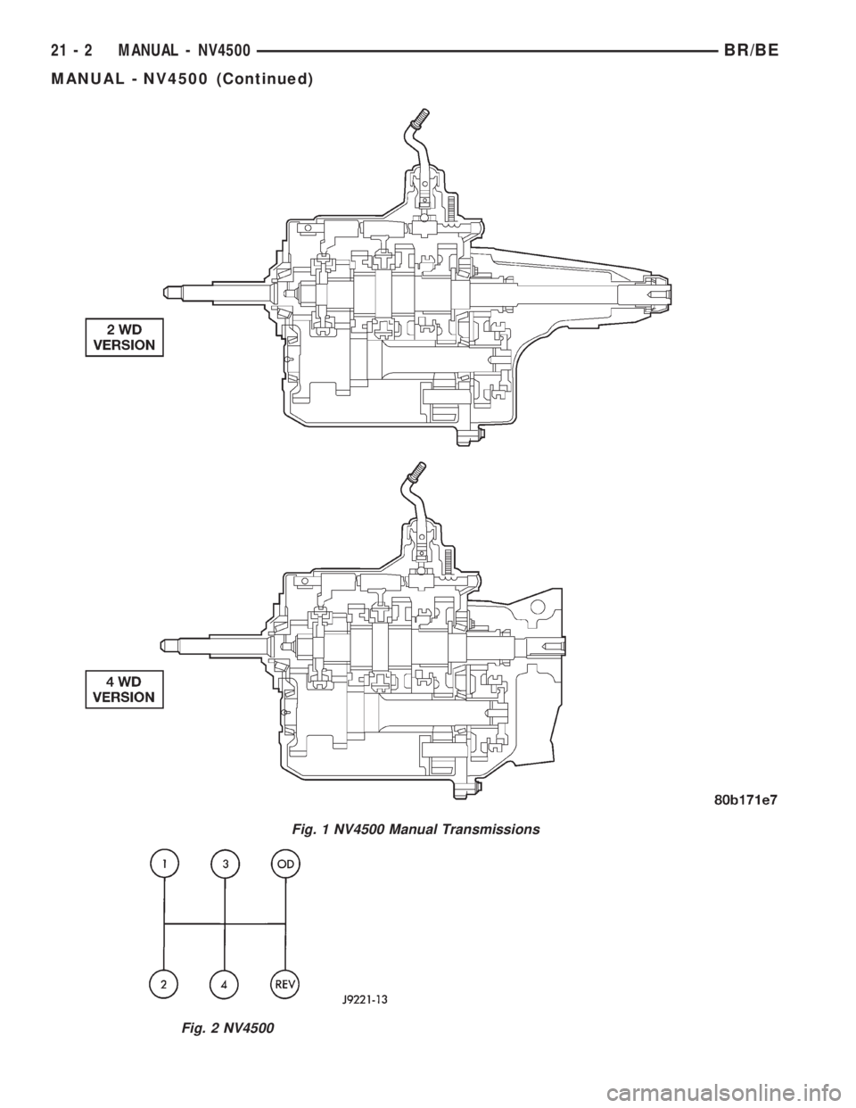
Fig. 1 NV4500 Manual Transmissions
Fig. 2 NV4500
21 - 2 MANUAL - NV4500BR/BE
MANUAL - NV4500 (Continued)
Page 1456 of 2255
GEAR RATIOS
GEAR RATIO
FIRST 5.61:1
SECOND 3.04:1
THIRD 1.67:1
FOURTH 1.00:1
FIFTH 0.75:1
REVERSE 5.04:1
IDENTIFICATION
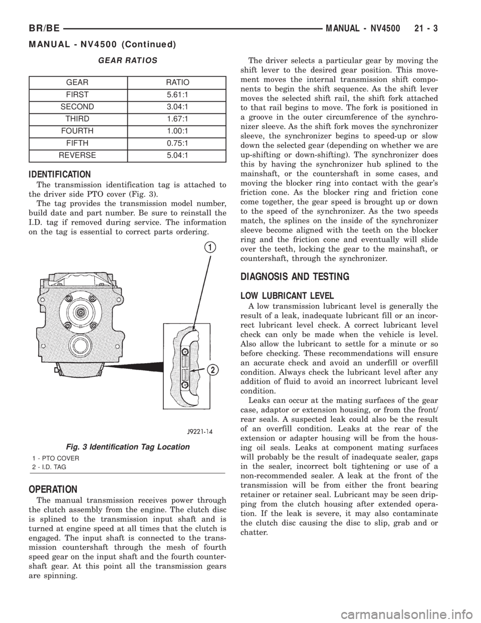
The transmission identification tag is attached to
the driver side PTO cover (Fig. 3).
The tag provides the transmission model number,
build date and part number. Be sure to reinstall the
I.D. tag if removed during service. The information
on the tag is essential to correct parts ordering.
OPERATION
The manual transmission receives power through
the clutch assembly from the engine. The clutch disc
is splined to the transmission input shaft and is
turned at engine speed at all times that the clutch is
engaged. The input shaft is connected to the trans-
mission countershaft through the mesh of fourth
speed gear on the input shaft and the fourth counter-
shaft gear. At this point all the transmission gears
are spinning.The driver selects a particular gear by moving the
shift lever to the desired gear position. This move-
ment moves the internal transmission shift compo-
nents to begin the shift sequence. As the shift lever
moves the selected shift rail, the shift fork attached
to that rail begins to move. The fork is positioned in
a groove in the outer circumference of the synchro-
nizer sleeve. As the shift fork moves the synchronizer
sleeve, the synchronizer begins to speed-up or slow
down the selected gear (depending on whether we are
up-shifting or down-shifting). The synchronizer does
this by having the synchronizer hub splined to the
mainshaft, or the countershaft in some cases, and
moving the blocker ring into contact with the gear's
friction cone. As the blocker ring and friction cone
come together, the gear speed is brought up or down
to the speed of the synchronizer. As the two speeds
match, the splines on the inside of the synchronizer
sleeve become aligned with the teeth on the blocker
ring and the friction cone and eventually will slide
over the teeth, locking the gear to the mainshaft, or
countershaft, through the synchronizer.
DIAGNOSIS AND TESTING
LOW LUBRICANT LEVEL
A low transmission lubricant level is generally the
result of a leak, inadequate lubricant fill or an incor-
rect lubricant level check. A correct lubricant level
check can only be made when the vehicle is level.
Also allow the lubricant to settle for a minute or so
before checking. These recommendations will ensure
an accurate check and avoid an underfill or overfill
condition. Always check the lubricant level after any
addition of fluid to avoid an incorrect lubricant level
condition.
Leaks can occur at the mating surfaces of the gear
case, adaptor or extension housing, or from the front/
rear seals. A suspected leak could also be the result
of an overfill condition. Leaks at the rear of the
extension or adapter housing will be from the hous-
ing oil seals. Leaks at component mating surfaces
will probably be the result of inadequate sealer, gaps
in the sealer, incorrect bolt tightening or use of a
non-recommended sealer. A leak at the front of the
transmission will be from either the front bearing
retainer or retainer seal. Lubricant may be seen drip-
ping from the clutch housing after extended opera-
tion. If the leak is severe, it may also contaminate
the clutch disc causing the disc to slip, grab and or
chatter.
Fig. 3 Identification Tag Location
1 - PTO COVER
2 - I.D. TAG
BR/BEMANUAL - NV4500 21 - 3
MANUAL - NV4500 (Continued)
Page 1457 of 2255
HARD SHIFTING
Hard shifting is usually caused by a low lubricant
level, improper or contaminated lubricants. The con-
sequence of using non-recommended lubricants is
noise, excessive wear, internal bind and hard shift-
ing. Substantial lubricant leaks can result in gear,
shift rail, synchro, and bearing damage. If a leak
goes undetected for an extended period, the first indi-
cations of component damage are usually hard shift-
ing and noise.
Component damage, incorrect clutch adjustment or
damaged clutch pressure plate or disc are additional
probable causes of increased shift effort. Incorrect
adjustment or a worn/damaged pressure plate or disc
can cause incorrect release. If clutch problem is
advanced, gear clash during shifts can result. Worn
or damaged synchro rings can cause gear clash when
shifting into any forward gear. In some new or
rebuilt transmissions, new synchro rings may tend to
stick slightly causing hard or noisy shifts. In most
cases this condition will decline as the rings wear-in.
TRANSMISSION NOISE
Most manual transmissions make some noise dur-
ing normal operation. Rotating gears generate a mild
whine that is audible, but generally only at extreme
speeds. Severe highly audible transmission noise is
generally the initial indicator of a lubricant problem.
Insufficient, improper or contaminated lubricant
will promote rapid wear of gears, synchros, shift
rails, forks and bearings. The overheating caused by
a lubricant problem, can also lead to gear breakage.
REMOVAL
(1) Disconnect battery negative cable.
(2) Shift transmission into Neutral.
(3) Remove shift boot screws from floorpan and
slide boot upward on the shift lever.
(4) Remove shift lever extension from shift tower
and lever assembly.
(5) Remove shift tower bolts holding tower to iso-
lator plate and transmission shift cover.
(6) Remove shift tower and isolator plate from
transmission shift cover.
(7) Raise and support vehicle.
(8) Remove skid plate, if equipped.
(9) Mark propeller shaft and axle yokes for instal-
lation reference and remove shaft/shafts.
(10) Remove exhaust system Y-pipe.
(11) Disconnect speed sensor and backup light
switch connectors.
(12) Support engine with safety stand and a wood
block.
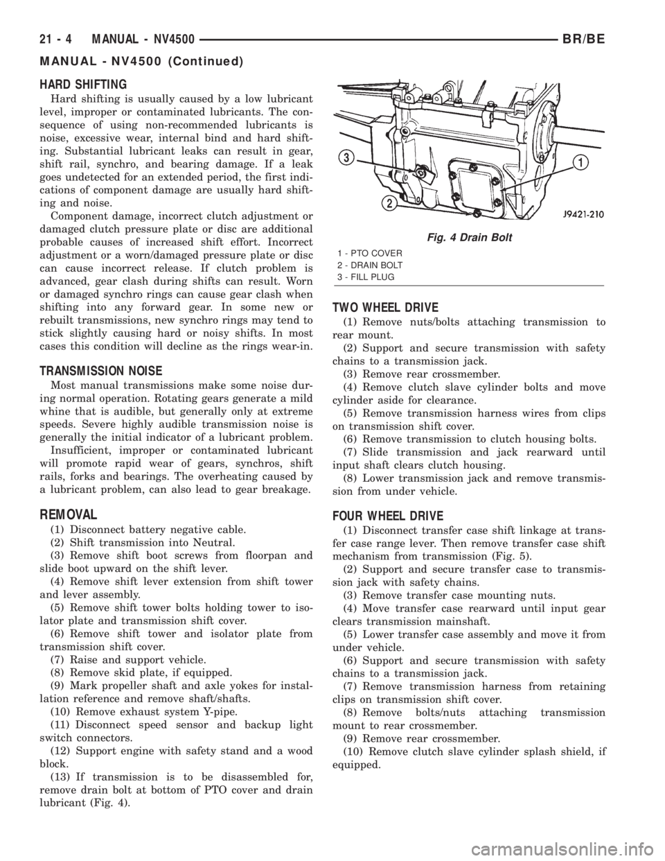
(13) If transmission is to be disassembled for,
remove drain bolt at bottom of PTO cover and drain
lubricant (Fig. 4).
TWO WHEEL DRIVE
(1) Remove nuts/bolts attaching transmission to
rear mount.
(2) Support and secure transmission with safety
chains to a transmission jack.
(3) Remove rear crossmember.
(4) Remove clutch slave cylinder bolts and move
cylinder aside for clearance.
(5) Remove transmission harness wires from clips
on transmission shift cover.
(6) Remove transmission to clutch housing bolts.
(7) Slide transmission and jack rearward until
input shaft clears clutch housing.
(8) Lower transmission jack and remove transmis-
sion from under vehicle.
FOUR WHEEL DRIVE
(1) Disconnect transfer case shift linkage at trans-
fer case range lever. Then remove transfer case shift
mechanism from transmission (Fig. 5).
(2) Support and secure transfer case to transmis-
sion jack with safety chains.
(3) Remove transfer case mounting nuts.
(4) Move transfer case rearward until input gear
clears transmission mainshaft.
(5) Lower transfer case assembly and move it from
under vehicle.
(6) Support and secure transmission with safety
chains to a transmission jack.
(7) Remove transmission harness from retaining
clips on transmission shift cover.
(8) Remove bolts/nuts attaching transmission
mount to rear crossmember.
(9) Remove rear crossmember.
(10) Remove clutch slave cylinder splash shield, if
equipped.
Fig. 4 Drain Bolt
1 - PTO COVER
2 - DRAIN BOLT
3 - FILL PLUG
21 - 4 MANUAL - NV4500BR/BE
MANUAL - NV4500 (Continued)
Page 1458 of 2255
(11) Loosen clutch slave cylinder attaching nuts
until cylinder piston rod is clear of release lever. This
reduces pressure on lever and release bearing mak-
ing transmission removal/installation easier. Cylinder
does not have to be removed completely.
(12) Remove transmission bolts from clutch hous-
ing.
(13) Move transmission rearward until input shaft
clears clutch disc and release bearing.
(14) Lower transmission and remove it from under
vehicle.
DISASSEMBLY
EXTENSION/ADAPTER HOUSING
(1) Raise and support vehicle.
(2) Remove rear propeller shaft.
(3) Support transmission with a transmission jack.
(4) Remove engine rear support.
(5) Remove transfer case, if equipped.
(6) Remove bolts attaching extension/adapter hous-
ing to gear case (Fig. 6).
(7) Remove extension/adapter housing (Fig. 7).
There is one alignment dowel in the gear case and
one in the extension/adapter housing.
(8) Remove rubber spline seal from end of main-
shaft (Fig. 8). The seal is used to prevent lubricant
loss during shipping and does not have to be replaced
if damaged.
FIFTH GEAR NUT
(1) Remove extension/adapter housing.
(2) Loosen fifth gear clamp nut clamping screw
approximately 1 1/2 turns.(3) Install nut Wrench 6743 on fifth gear nut (Fig.
9).
NOTE: Wrench only fits one way on nut. Make sure
wrench is fully engaged in nut slots and is not
cocked.
Fig. 5 Transfer Case Shift Mechanism-Typical
1 - TRANSMISSION
2 - TRANSFER CASE SHIFT MECHANISM
Fig. 6 Extension/Adapter Housing Bolts
1 - EXTENSION HOUSING
2 - BOLTS (8)
Fig. 7 Extension/Adapter Housing
1 - GEAR CASE
2 - EXTENSION HOUSING
BR/BEMANUAL - NV4500 21 - 5
MANUAL - NV4500 (Continued)