DODGE RAM 2002 Service Repair Manual
Manufacturer: DODGE, Model Year: 2002, Model line: RAM, Model: DODGE RAM 2002Pages: 2255, PDF Size: 62.07 MB
Page 571 of 2255
OPERATION - REMOTE KEYLESS ENTRY
SYSTEM
On vehicles with the Remote Keyless Entry (RKE)
system, the power locks can be operated remotely
using the RKE transmitter. If the vehicle is so
equipped, the RKE transmitter also arms and dis-
arms the factory-installed Vehicle Theft Security Sys-
tem (VTSS). Three small, recessed buttons on the
outside of the transmitter case labelled Lock, Unlock,
and Panic allow the user to choose the function that
is desired. The RKE transmitter then sends the
appropriate Radio Frequency (RF) signal. An RF
receiver that is integral to the high-line or premium
version of the Central Timer Module (CTM) receives
the transmitted signal, then uses its internal elec-
tronic programming to determine whether the
received signal is valid and what function has been
requested. If the signal is valid, the CTM provides
the programmed features.
Besides operating the power lock system and arm-
ing or disarming the VTSS, the RKE system also
controls the following features:
²Horn Chirp- If this feature is enabled, the
CTM provides a horn chirp by internally pulling the
control coil of the horn relay to ground through a
hard wired circuit output.
²Illuminated Entry- The CTM provides illumi-
nated entry by internally controlling the current flow
to the courtesy lamps in the vehicle through a hard
wired output circuit.
²Panic Mode- The CTM provides the horn pulse
and headlight flash by internally pulling the control
coils of the horn relay and headlamp relay to ground
through hard wired circuit outputs. The CTM con-
trols the current flow to the courtesy lamps in the
vehicle through a hard wired output circuit. The
CTM also monitors the vehicle speed through elec-
tronic messages it receives from the Powertrain Con-
trol Module (PCM) over the Chrysler Collision
Detection (CCD) data bus network.
The RKE system operates on battery current
received through a fused B(+) circuit from a fuse in
the Junction Block (JB) so that the system remains
functional, regardless of the ignition switch position.
The RKE system can retain the vehicle access codes
of up to four RKE transmitters. The transmitter
codes are retained in RKE system memory, even if
the battery is disconnected. If a transmitter is faulty
or is lost, new transmitter vehicle access codes can be
programmed into the system using a DRBIIItscan
tool. Refer to the appropriate diagnostic information.
Many of the electronic features in the vehicle con-
trolled or supported by the high-line or premium ver-
sions of the CTM are programmable using the
DRBIIItscan tool. In addition, the high-line/pre-
mium CTM software is Flash compatible, whichmeans it can be reprogrammed using Flash repro-
gramming procedures. However, if any of the CTM
hardware components are damaged or faulty, the
entire CTM unit must be replaced. The hard wired
inputs or outputs of the CTM can be diagnosed using
conventional diagnostic tools and methods; however,
for diagnosis of the high-line or premium versions of
the CTM or the CCD data bus, the use of a DRBIIIt
scan tool is required. Refer to the appropriate diag-
nostic information.
DIAGNOSIS AND TESTING
DIAGNOSIS AND TESTING - POWER LOCKS
The following tests provide a preliminary diagnosis
for the power lock system usedonlyon vehicles
equipped with a base version of the Central Timer
Module (CTM). These testsdo notapply to the diag-
nosis of the power lock system used on vehicles
equipped with the optional Remote Keyless Entry
(RKE) system, which includes a high-line or premium
CTM. (Refer to 8 - ELECTRICAL/POWER LOCKS -
DIAGNOSIS AND TESTING - POWER LOCK &
REMOTE KEYLESS ENTRY SYSTEM). Refer to the
appropriate wiring information. The wiring informa-
tion includes wiring diagrams, proper wire and con-
nector repair procedures, details of wire harness
routing and retention, connector pin-out information
and location views for the various wire harness con-
nectors, splices and grounds.
PRELIMINARY TESTS
To begin this test, note the system operation while
you actuate both the Lock and Unlock functions with
the power lock switches. Then, proceed as follows:
²If the entire power lock system fails to function
with both of the power lock switches, check the fused
B(+) fuse in the Junction Block (JB). If the fuse is
OK, check the ground circuit between the driver side
power lock switch and ground (G301). If the ground
circuit is OK, proceed to the diagnosis of the power
lock motors. (Refer to 8 - ELECTRICAL/POWER
LOCKS/POWER LOCK MOTOR - DIAGNOSIS AND
TESTING).
²If the entire power lock system fails to function
with only one of the power lock switches, proceed to
diagnosis of the power lock switches. (Refer to 8 -
ELECTRICAL/POWER LOCKS/POWER LOCK
SWITCH - DIAGNOSIS AND TESTING).
²If only one power lock motor fails to operate
with both power lock switches, proceed to diagnosis
of the power lock motor. (Refer to 8 - ELECTRICAL/
POWER LOCKS/POWER LOCK MOTOR - DIAGNO-
SIS AND TESTING).
8N - 4 POWER LOCKSBR/BE
POWER LOCKS (Continued)
Page 572 of 2255
DIAGNOSIS AND TESTING - POWER LOCK &
REMOTE KEYLESS ENTRY SYSTEM
The following tests include a preliminary diagnosis
for the power lock system usedonlyon vehicles
equipped with the optional Remote Keyless Entry
(RKE) system, which includes a high-line or premium
Central Timer Module (CTM). These testsdo not
apply to the diagnosis of the power lock system on
vehicles equipped with a base version of the CTM.
(Refer to 8 - ELECTRICAL/POWER LOCKS - DIAG-
NOSIS AND TESTING - POWER LOCK SYSTEM).
These tests will help to diagnose the hard wired
components and circuits of the power lock system.
However, these tests may not prove conclusive in the
diagnosis of this system. In order to obtain conclusive
testing of the power lock and RKE system, the
Chrysler Collision Detection (CCD) data bus network
and all of the electronic modules that provide inputs
to, or receive outputs from the power lock and RKE
system components must be checked.
The most reliable, efficient, and accurate means to
diagnose the power lock and RKE system requires
the use of a DRBIIItscan tool. The DRBIIItscan
tool can provide confirmation that the CCD data bus
is functional, that all of the electronic modules are
sending and receiving the proper messages on the
CCD data bus, that the CTM is receiving the proper
hard wired inputs, and that the power lock motors
are being sent the proper hard wired outputs by the
CTM.
Refer to the appropriate wiring information. The
wiring information includes wiring diagrams, proper
wire and connector repair procedures, details of wire
harness routing and retention, connector pin-out
information and location views for the various wire
harness connectors, splices and grounds.
PRELIMINARY TESTS
To begin this test, note the system operation while
you actuate both the Lock and Unlock functions with
the power lock switches, the door cylinder lock
switches, and the RKE transmitter. Then, proceed as
follows:
²If the entire power lock system fails to function
with the power lock switches, the door cylinder lock
switches, or the RKE transmitter, check the fused
B(+) fuse in the Junction Block (JB). If the fuse is
OK, proceed to the diagnosis of the power lock
motors. (Refer to 8 - ELECTRICAL/POWER LOCKS/
POWER LOCK MOTOR - DIAGNOSIS AND TEST-
ING).
²If the power lock system functions with both
power lock switches, and both door cylinder lock
switches, but not with the RKE transmitter, proceed
to the diagnosis of the transmitter. (Refer to 8 -
ELECTRICAL/POWER LOCKS/REMOTE KEYLESSENTRY TRANSMITTER - DIAGNOSIS AND TEST-
ING).
²If the entire power lock system functions with
the RKE transmitter, and both door cylinder lock
switches, but not with one or both of the power lock
switches, proceed to diagnosis of the power lock
switches. (Refer to 8 - ELECTRICAL/POWER
LOCKS/POWER LOCK SWITCH - DIAGNOSIS AND
TESTING).
²If the entire power lock system functions with
the RKE transmitter, and both power lock switches,
but not with one or both of the door cylinder lock
switches, proceed to diagnosis of the door cylinder
lock switches. (Refer to 8 - ELECTRICAL/POWER
LOCKS/DOOR CYLINDER LOCK SWITCH - DIAG-
NOSIS AND TESTING).
²If one power lock motor fails to operate with
both of the power lock switches, both of the door cyl-
inder lock switches and/or the RKE transmitter, pro-
ceed to diagnosis of the power lock motor. (Refer to 8
- ELECTRICAL/POWER LOCKS/POWER LOCK
MOTOR - DIAGNOSIS AND TESTING).
If the problem being diagnosed is related to one or
more of the electronic features (automatic locks, door
lock inhibit, enhanced accident response, illuminated
entry, panic mode, or RKE horn chirp), further diag-
nosis should be performed using a DRBIIItscan tool.
Refer to the appropriate diagnostic information.
DOOR CYLINDER LOCK
SWITCH
DESCRIPTION
A door cylinder lock switch is snapped onto the
back of the key lock cylinder inside each front door of
vehicles equipped with a high-line or premium Cen-
tral Timer Module (CTM). The door cylinder lock
switch is a resistor multiplexed momentary switch
that is hard wired in series between a body ground
and the CTM through the front door wire harness.
The door cylinder lock switches are driven by the key
lock cylinders and contain three internal resistors.
One resistor is used for the neutral switch position,
one for the Lock position, and one for the Unlock
position.
The door cylinder lock switches cannot be adjusted
or repaired and, if faulty or damaged, they must be
replaced.
OPERATION
The door cylinder lock switches are actuated by the
key lock cylinder when the key is inserted in the lock
cylinder and turned to the lock or unlock positions.
The door cylinder lock switch closes a path to ground
through one of three internal resistors for the Cen-
BR/BEPOWER LOCKS 8N - 5
POWER LOCKS (Continued)
Page 573 of 2255
tral Timer Module (CTM) when the front door key
lock cylinder is in the Lock, Unlock, or Neutral posi-
tions. The CTM reads the switch status through an
internal pull-up, then uses this information as an
input for both power lock system and Vehicle Theft
Security System (VTSS) operation.
The door cylinder lock switches and circuits can be
diagnosed using conventional diagnostic tools and
methods.
DIAGNOSIS AND TESTING - DOOR CYLINDER
LOCK SWITCH
Refer to the appropriate wiring information. The
wiring information includes wiring diagrams, proper
wire and connector repair procedures, details of wire
harness routing and retention, connector pin-out
information and location views for the various wire
harness connectors, splices and grounds.
(1) Disconnect the door cylinder lock switch pigtail
wire connector from the door wire harness connector.
(2) Using an ohmmeter, perform the switch resis-
tance checks between the two cavities of the door cyl-
inder lock switch pigtail wire connector. Actuate the
switch by rotating the key in the door lock cylinder
to test for the proper resistance values in each of the
three switch positions, as shown in the Door Cylinder
Lock Switch chart.
DOOR CYLINDER LOCK SWITCH
Switch Position
Resistance
Driver Side Passenger Side
Neutral Neutral 12 Kilohms
Lock (Clockwise)Lock (Counter
Clockwise)644 Ohms
Unlock (Counter
Clockwise)Unlock
(Clockwise)1565 Ohms
(3) If a door cylinder lock switch fails any of the
resistance tests, replace the faulty switch as
required.
REMOVAL
(1) Disconnect and isolate the battery negative
cable.
(2) Remove the door outside latch handle mount-
ing hardware and linkage from the inside of the door.
(Refer to 23 - BODY/DOOR - FRONT/EXTERIOR
HANDLE - REMOVAL).
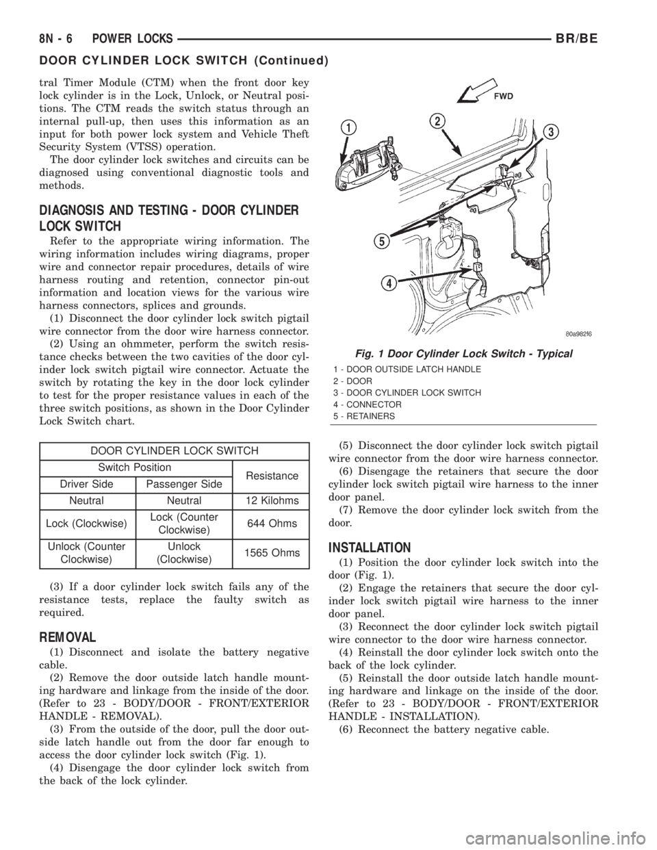
(3) From the outside of the door, pull the door out-
side latch handle out from the door far enough to
access the door cylinder lock switch (Fig. 1).
(4) Disengage the door cylinder lock switch from
the back of the lock cylinder.(5) Disconnect the door cylinder lock switch pigtail
wire connector from the door wire harness connector.
(6) Disengage the retainers that secure the door
cylinder lock switch pigtail wire harness to the inner
door panel.
(7) Remove the door cylinder lock switch from the
door.
INSTALLATION
(1) Position the door cylinder lock switch into the
door (Fig. 1).
(2) Engage the retainers that secure the door cyl-
inder lock switch pigtail wire harness to the inner
door panel.
(3) Reconnect the door cylinder lock switch pigtail
wire connector to the door wire harness connector.
(4) Reinstall the door cylinder lock switch onto the
back of the lock cylinder.
(5) Reinstall the door outside latch handle mount-
ing hardware and linkage on the inside of the door.
(Refer to 23 - BODY/DOOR - FRONT/EXTERIOR
HANDLE - INSTALLATION).
(6) Reconnect the battery negative cable.
Fig. 1 Door Cylinder Lock Switch - Typical
1 - DOOR OUTSIDE LATCH HANDLE
2 - DOOR
3 - DOOR CYLINDER LOCK SWITCH
4 - CONNECTOR
5 - RETAINERS
8N - 6 POWER LOCKSBR/BE
DOOR CYLINDER LOCK SWITCH (Continued)
Page 574 of 2255
POWER LOCK MOTOR
DESCRIPTION
Models equipped with the optional power lock sys-
tem have a power operated door locking mechanism
located within each front door. The lock mechanisms
are actuated by a reversible electric power lock motor
that is integral to the door latch unit within each
front door. A single short pigtail wire with a molded
plastic connector insulator connects the door lock
motor to the vehicle electrical system through a take
out and connector of each front door wire harness.
The power lock motors cannot be adjusted or
repaired and, if faulty or damaged, the entire door
latch unit must be replaced.
OPERATION
On models with a base version of the Central
Timer Module (CTM), the power lock motor is con-
trolled by the battery and ground feeds from the
power lock switches. On models with the high-line or
premium versions of the CTM, the power lock motor
is controlled by the battery and ground feeds from
the power lock and unlock relays, which are integral
and internal to the high-line and premium versions
of the CTM. A positive and negative battery connec-
tion to the two motor terminals will cause the power
lock motor plunger to move in one direction. Revers-
ing the current through these same two connections
will cause the power lock motor plunger to move in
the opposite direction.
The power lock motors and circuits can be tested
using conventional diagnostic tools and methods.
DIAGNOSIS AND TESTING - POWER LOCK
MOTOR
On models with a base version of the Central
Timer Module (CTM), confirm proper power lock
switch operation before you proceed with this diagno-
sis. On models with a high-line or premium version
of the CTM, confirm proper power lock switch, power
lock switch output circuit, and CTM operation before
you proceed with this diagnosis. Remember, the
power lock switch controls the output to the power
lock motors on models with a base CTM, while the
CTM controls the output to the power lock motors on
models with a high-line or premium CTM. Refer to
the appropriate wiring information. The wiring infor-
mation includes wiring diagrams, proper wire and
connector repair procedures, details of wire harness
routing and retention, connector pin-out information
and location views for the various wire harness con-
nectors, splices and grounds.
(1) Check each power lock motor for correct opera-
tion while moving the power lock switch to both theLock and Unlock positions. If both of the power lock
motors are inoperative, go to Step 2. If one power
lock motor is inoperative, go to Step 3.
(2) If both of the power lock motors are inopera-
tive, the problem may be caused by one shorted
motor. Disconnecting a shorted power lock motor
from the power lock circuit will allow the good power
lock motors to operate. Disconnect the wire harness
connector from each power lock motor, one at a time,
and recheck both the lock and unlock functions by
operating the power lock switch. If both power lock
motors are still inoperative after the above test,
check for a short or open circuit between the power
lock motors and either the power lock switch (base
CTM) or the CTM (high-line or premium CTM). If
disconnecting one power lock motor causes the other
motor to become functional, go to Step 3 to test the
disconnected motor.
(3) Once it is determined which power lock motor
is inoperative, that motor can be tested as follows.
Disconnect the door wire harness connector from the
inoperative power lock motor. Apply 12 volts to the
lock and unlock driver circuit cavities of the power
lock motor pigtail wire connector to check its opera-
tion in one direction. Reverse the polarity to check
the motor operation in the opposite direction. If OK,
repair the shorted or open circuits between the power
lock motor and the power lock switch (base CTM) or
the CTM (high-line or premium CTM) as required. If
not OK, replace the faulty power lock motor.
REMOTE KEYLESS ENTRY
TRANSMITTER
DESCRIPTION
The Remote Keyless Entry (RKE) system Radio
Frequency (RF) transmitter is equipped with three
buttons, labeled Lock, Unlock, and Panic. It is also
equipped with a key ring and is designed to serve as
a key fob. The operating range of the transmitter
radio signal is up to 7 meters (23 feet) from the RKE
receiver. The RKE receiver is integral to the high-
line or premium Central Timer Module (CTM) in this
vehicle.
Each RKE transmitter has a different vehicle
access code, which must be programmed into the
memory of the RKE receiver in the vehicle in order
to operate the RKE system. The RKE receiver can
retain the access codes for up to four transmitters in
its memory. (Refer to 8 - ELECTRICAL/POWER
LOCKS/REMOTE KEYLESS ENTRY TRANSMIT-
TER - STANDARD PROCEDURE - RKE TRANS-
MITTER PROGRAMMING).
BR/BEPOWER LOCKS 8N - 7
Page 575 of 2255
The RKE transmitter operates on two Duracell
DL2016, Panasonic CR2016 (or equivalent) batteries.
Typical battery life is from one to two years. The
RKE transmitter cannot be repaired and, if faulty or
damaged, it must be replaced.
OPERATION
See the owner's manual in the vehicle glove box for
more information on the features, use and operation
of the Remote Keyless Entry (RKE) transmitters.
DIAGNOSIS AND TESTING - REMOTE KEYLESS
ENTRY TRANSMITTER
(1) Replace the Remote Keyless Entry (RKE)
transmitter batteries. (Refer to 8 - ELECTRICAL/
POWER LOCKS/REMOTE KEYLESS ENTRY
TRANSMITTER - STANDARD PROCEDURE - RKE
TRANSMITTER BATTERIES). Test each of the RKE
transmitter functions. If OK, discard the faulty bat-
teries. If not OK, go to Step 2.
(2) Program the suspect RKE transmitter and
another known good transmitter into the RKE
receiver. (Refer to 8 - ELECTRICAL/POWER
LOCKS/REMOTE KEYLESS ENTRY TRANSMIT-
TER - STANDARD PROCEDURE - RKE TRANS-
MITTER PROGRAMMING).
(3) Test the RKE system operation with both
transmitters. If both transmitters fail to operate the
power lock system, a DRBIIItscan tool is required
for further diagnosis of the RKE system. Refer to the
appropriate diagnostic information. If the known
good RKE transmitter operates the power locks and
the suspect transmitter does not, replace the faulty
RKE transmitter.
NOTE: Be certain to perform the RKE Transmitter
Programming procedure again following this test.
This procedure will erase the access code of the
test transmitter from the RKE receiver.
STANDARD PROCEDURE
STANDARD PROCEDURE - RKE TRANSMITTER
PROGRAMMING
To program the Remote Keyless Entry (RKE)
transmitter access codes into the RKE receiver in the
high-line or premium Central Timer Module (CTM)
requires the use of a DRBIIItscan tool. Refer to the
appropriate diagnostic information.
STANDARD PROCEDURE - REMOTE KEYLESS
ENTRY TRANSMITTER BATTERIES
The Remote Keyless Entry (RKE) transmitter case
snaps open and shut for battery access. To replace
the RKE transmitter batteries:
(1) Using a trim stick or a thin coin, gently pry at
the notch in the center seam of the RKE transmitter
case halves located near the key ring until the two
halves unsnap.
(2) Lift the back half of the transmitter case off of
the RKE transmitter.
(3) Remove the two batteries from the RKE trans-
mitter.
(4) Replace the two batteries with new Duracell
DL2016, or their equivalent. Be certain that the bat-
teries are installed with their polarity correctly ori-
ented.
(5) Align the two RKE transmitter case halves
with each other, and squeeze them firmly and evenly
together using hand pressure until they snap back
into place.
POWER LOCK SWITCH
DESCRIPTION
The power lock system can be controlled by a two-
way momentary switch integral to the power window
and lock switch and bezel unit on the trim panel of
each front door. Each power lock switch is illumi-
nated by a Light-Emitting Diode (LED) that is inte-
gral to the switch paddle. The LED of each switch is
illuminated whenever the ignition switch is in the
On position.
The power lock switches and their LEDs cannot be
adjusted or repaired and, if faulty or damaged, the
entire power window and lock switch and bezel unit
must be replaced.
OPERATION
On models with a base version of the Central
Timer Module (CTM), the power lock switches are
hard-wired to the power lock motors. The power lock
switch provides the correct battery and ground feeds
to the power lock motors to lock or unlock the door
latches.
On models with a high-line or premium version of
the CTM, the power lock switch controls battery cur-
rent signals to the lock and unlock sense inputs of
the CTM. The CTM then relays the correct battery
and ground feeds to the power lock motors to lock or
unlock the door latches.
8N - 8 POWER LOCKSBR/BE
REMOTE KEYLESS ENTRY TRANSMITTER (Continued)
Page 576 of 2255
DIAGNOSIS AND TESTING - POWER LOCK
SWITCH
The Light-Emitting Diode (LED) illumination
lamps for all of the power window and lock switch
and bezel unit switch paddles receive battery current
through the power window circuit breaker in the
Junction Block (JB). If all of the LEDs are inopera-
tive in either or both power window and lock switch
and bezel units, be certain to diagnose the power
window system before replacing the switch unit.
(Refer to 8 - ELECTRICAL/POWER WINDOWS -
DIAGNOSIS AND TESTING). If only one LED in a
power window and lock switch and bezel unit is inop-
erative, replace the faulty switch and bezel unit.
Refer to the appropriate wiring information. The wir-
ing information includes wiring diagrams, proper
wire and connector repair procedures, details of wire
harness routing and retention, connector pin-out
information and location views for the various wire
harness connectors, splices and grounds.
(1) Check the fused B(+) fuse (Fuse 13 - 10
ampere) in the Junction Block (JB). If OK, go to Step
2. If not OK, repair the shorted circuit or component
as required and replace the faulty fuse.
(2) Check for battery voltage at the fused B(+) fuse
(Fuse 13 - 10 ampere) in the JB. If OK, go to Step 3.
If not OK, repair the open fused B(+) circuit between
the JB and the Power Distribution Center (PDC) as
required.
(3) Disconnect and isolate the battery negative
cable. Remove the power window and lock switch and
bezel unit from the door trim panel. Disconnect the
door wire harness connector for the power window
and lock switch unit from the switch connector recep-
tacle.
(4) Reconnect the battery negative cable. Check for
battery voltage at the fused B(+) circuit cavity of the
door wire harness connector for the power window
and lock switch unit. If OK, go to Step 5. If not OK,
repair the open fused B(+) circuit between the power
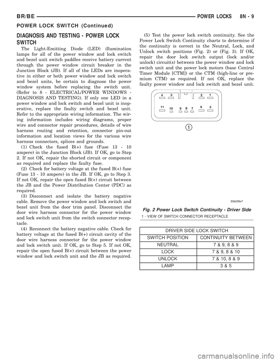
window and lock switch unit and the JB as required.(5) Test the power lock switch continuity. See the
Power Lock Switch Continuity charts to determine if
the continuity is correct in the Neutral, Lock, and
Unlock switch positions (Fig. 2) or (Fig. 3). If OK,
repair the door lock switch output (lock and/or
unlock) circuit(s) between the power window and lock
switch unit and the power lock motors (base Central
Timer Module [CTM]) or the CTM (high-line or pre-
mium CTM) as required. If not OK, replace the
faulty power window and lock switch and bezel unit.
DRIVER SIDE LOCK SWITCH
SWITCH POSITION CONTINUITY BETWEEN
NEUTRAL 7 & 9,8&9
LOCK 7 & 9,8&10
UNLOCK 7 & 10,8&9
LAMP 3 & 5
Fig. 2 Power Lock Switch Continuity - Driver Side
1 - VIEW OF SWITCH CONNECTOR RECEPTACLE
BR/BEPOWER LOCKS 8N - 9
POWER LOCK SWITCH (Continued)
Page 577 of 2255
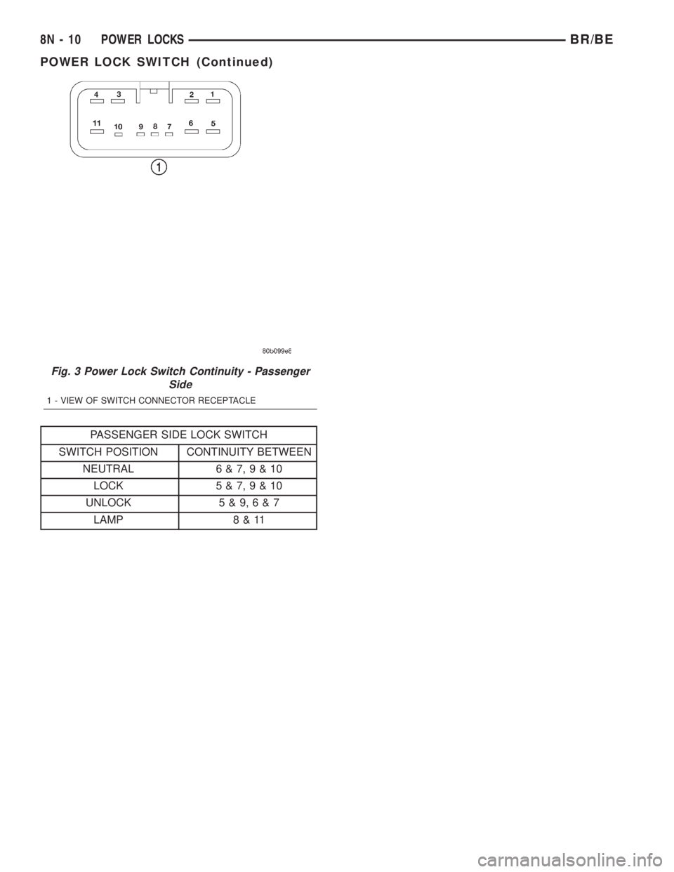
PASSENGER SIDE LOCK SWITCH
SWITCH POSITION CONTINUITY BETWEEN
NEUTRAL 6 & 7,9&10
LOCK 5 & 7,9&10
UNLOCK 5 & 9,6&7
LAMP 8 & 11
Fig. 3 Power Lock Switch Continuity - Passenger
Side
1 - VIEW OF SWITCH CONNECTOR RECEPTACLE
8N - 10 POWER LOCKSBR/BE
POWER LOCK SWITCH (Continued)
Page 578 of 2255
POWER MIRRORS
TABLE OF CONTENTS
page page
POWER MIRRORS
DESCRIPTION.........................11
OPERATION...........................11
AUTOMATIC DAY / NIGHT MIRROR
DESCRIPTION.........................11
OPERATION...........................12
DIAGNOSIS AND TESTING - AUTOMATIC
DAY/NIGHT MIRROR...................12
REMOVAL.............................13
INSTALLATION.........................13
POWER MIRROR SWITCH
DESCRIPTION.........................13OPERATION...........................13
REMOVAL.............................13
INSTALLATION.........................14
SIDEVIEW MIRROR
DESCRIPTION.........................14
OPERATION...........................14
DIAGNOSIS AND TESTING - SIDEVIEW
MIRROR............................14
REMOVAL.............................15
POWER MIRRORS
DESCRIPTION
AUTOMATIC DAY / NIGHT MIRROR
The automatic day/night mirror system is able to
automatically change the reflectance of the inside
rear view mirror in order to reduce the glare of head-
lamps approaching the vehicle from the rear. The
automatic day/night rear view mirror receives bat-
tery current through a fuse in the junction block only
when the ignition switch is in the On position.
OUTSIDE REAR VIEW MIRROR
The heated mirror option includes an electric heat-
ing grid behind the mirror glass in each outside mir-
ror, which can clear the mirror glass of ice, snow, or
fog. The heating grid receives fused battery current
through the heated mirror relay in the heater and air
conditioner control only when the ignition switch is
in the On position, and the heated mirror system is
turned on. (Refer to 8 - ELECTRICAL/HEATED
MIRRORS - DESCRIPTION) for more information.
Refer to the owner's manual in the vehicle glove
box for more information on the features, use and
operation of the power mirror system.
OPERATION
AUTOMATIC DAY / NIGHT MIRROR
A switch located on the bottom of the automatic
day/night mirror housing allows the vehicle operator
to select whether the automatic dimming feature is
operational. When the automatic day/night mirror isturned on, the mirror switch is lighted by an integral
Light-Emitting Diode (LED). The mirror will auto-
matically disable its self-dimming feature whenever
the vehicle is being driven in reverse.
Refer to the owner's manual in the vehicle glove
box for more information on the features, use and
operation of the automatic day/night mirror system.
OUTSIDE REAR VIEW MIRROR
The heated mirror option includes an electric heat-
ing grid behind the mirror glass in each outside mir-
ror, which can clear the mirror glass of ice, snow, or
fog. The heating grid receives fused battery current
through the heated mirror relay in the heater and air
conditioner control only when the ignition switch is
in the On position, and the heated mirror system is
turned on. (Refer to 8 - ELECTRICAL/HEATED
MIRRORS - OPERATION) for more information.
Refer to the owner's manual in the vehicle glove
box for more information on the features, use and
operation of the power mirror system.
AUTOMATIC DAY / NIGHT
MIRROR
DESCRIPTION
The automatic day/night mirror uses a thin layer
of electrochromic material between two pieces of con-
ductive glass to make up the face of the mirror.
When the mirror switch is in the On position, two
photocell sensors are used by the mirror circuitry to
monitor external light levels and adjust the reflec-
tance of the mirror.
BR/BEPOWER MIRRORS 8N - 11
Page 579 of 2255
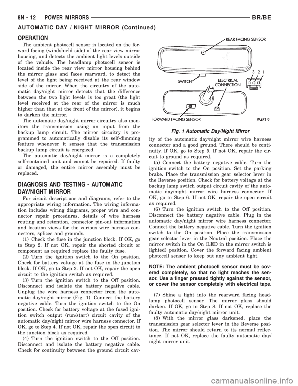
OPERATION
The ambient photocell sensor is located on the for-
ward-facing (windshield side) of the rear view mirror
housing, and detects the ambient light levels outside
of the vehicle. The headlamp photocell sensor is
located inside the rear view mirror housing behind
the mirror glass and faces rearward, to detect the
level of the light being received at the rear window
side of the mirror. When the circuitry of the auto-
matic day/night mirror detects that the difference
between the two light levels is too great (the light
level received at the rear of the mirror is much
higher than that at the front of the mirror), it begins
to darken the mirror.
The automatic day/night mirror circuitry also mon-
itors the transmission using an input from the
backup lamp circuit. The mirror circuitry is pro-
grammed to automatically disable its self-dimming
feature whenever it senses that the transmission
backup lamp circuit is energized.
The automatic day/night mirror is a completely
self-contained unit and cannot be repaired. If faulty
or damaged, the entire mirror assembly must be
replaced.
DIAGNOSIS AND TESTING - AUTOMATIC
DAY/NIGHT MIRROR
For circuit descriptions and diagrams, refer to the
appropriate wiring information. The wiring informa-
tion includes wiring diagrams, proper wire and con-
nector repair procedures, details of wire harness
routing and retention, connector pin-out information
and location views for the various wire harness con-
nectors, splices and grounds.
(1) Check the fuse in the junction block. If OK, go
to Step 2. If not OK, repair the shorted circuit or
component as required replace the faulty fuse.
(2) Turn the ignition switch to the On position.
Check for battery voltage at the fuse in the junction
block. If OK, go to Step 3. If not OK, repair the open
circuit to the ignition switch as required.
(3) Turn the ignition switch to the Off position.
Disconnect and isolate the battery negative cable.
Unplug the wire harness connector from the auto-
matic day/night mirror (Fig. 1). Connect the battery
negative cable. Turn the ignition switch to the On
position. Check for battery voltage at the fused igni-
tion switch output (run/start) circuit cavity of the
automatic day/night mirror wire harness connector. If
OK, go to Step 4. If not OK, repair the open circuit to
the junction block as required.
(4) Turn the ignition switch to the Off position.
Disconnect and isolate the battery negative cable.
Check for continuity between the ground circuit cav-ity of the automatic day/night mirror wire harness
connector and a good ground. There should be conti-
nuity. If OK, go to Step 5. If not OK, repair the cir-
cuit to ground as required.
(5) Connect the battery negative cable. Turn the
ignition switch to the On position. Set the parking
brake. Place the transmission gear selector lever in
the Reverse position. Check for battery voltage at the
backup lamp switch output circuit cavity of the auto-
matic day/night mirror wire harness connector. If
OK, go to Step 6. If not OK, repair the open circuit
as required.
(6) Turn the ignition switch to the Off position.
Disconnect the battery negative cable. Plug in the
automatic day/night mirror wire harness connector.
Connect the battery negative cable. Turn the ignition
switch to the On position. Place the transmission
gear selector lever in the Neutral position. Place the
mirror switch in the On (LED in the mirror switch is
lighted) position. Cover the forward facing ambient
photocell sensor to keep out any ambient light.
NOTE: The ambient photocell sensor must be cov-
ered completely, so that no light reaches the sen-
sor. Use a finger pressed tightly against the sensor,
or cover the sensor completely with electrical tape.
(7) Shine a light into the rearward facing head-
lamp photocell sensor. The mirror glass should
darken. If OK, go to Step 8. If not OK, replace the
faulty automatic day/night mirror unit.
(8) With the mirror glass darkened, place the
transmission gear selector lever in the Reverse posi-
tion. The mirror should return to its normal reflec-
tance. If not OK, replace the faulty automatic day/
night mirror unit.
Fig. 1 Automatic Day/Night Mirror
8N - 12 POWER MIRRORSBR/BE
AUTOMATIC DAY / NIGHT MIRROR (Continued)
Page 580 of 2255
REMOVAL
(1) Disconnect and isolate the battery negative
cable.
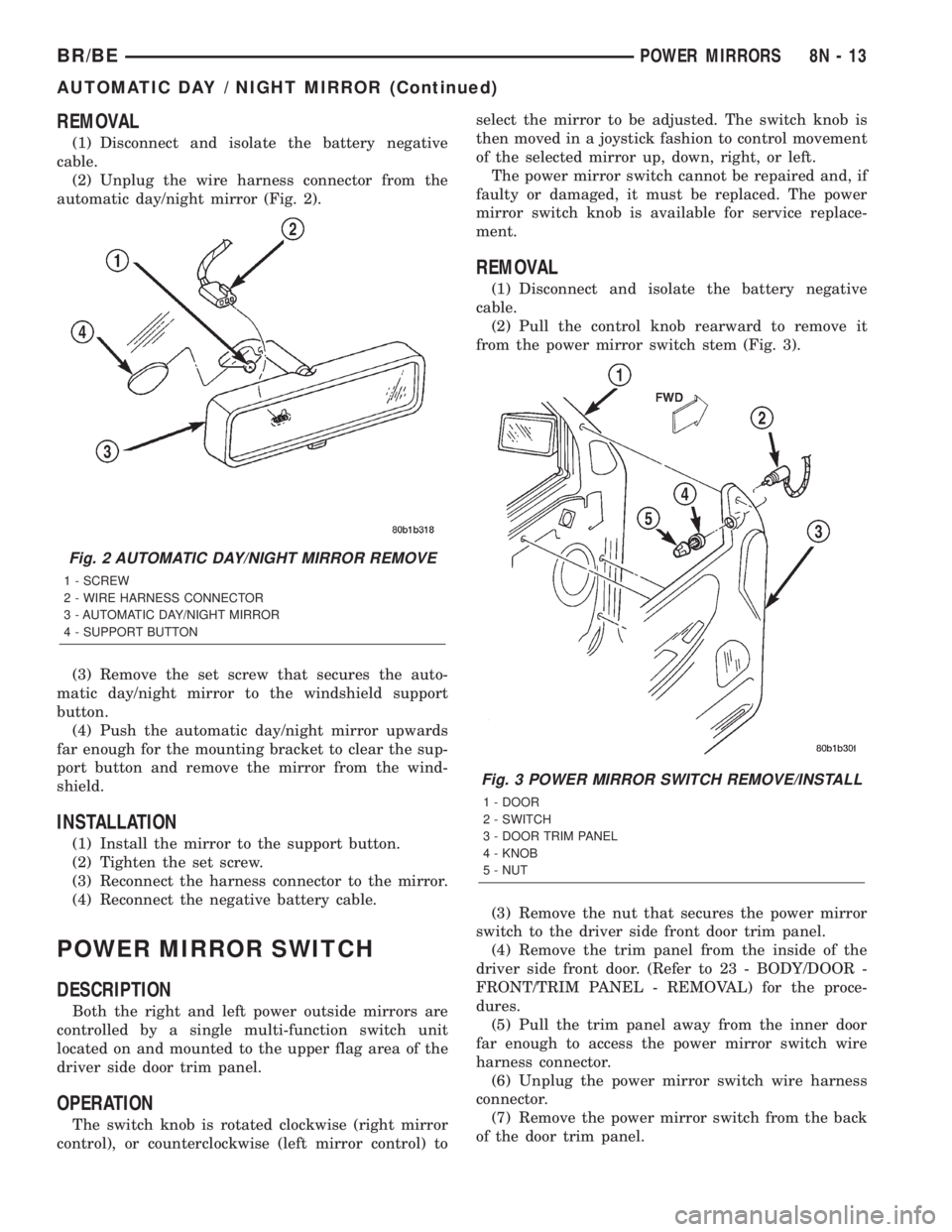
(2) Unplug the wire harness connector from the
automatic day/night mirror (Fig. 2).
(3) Remove the set screw that secures the auto-
matic day/night mirror to the windshield support
button.
(4) Push the automatic day/night mirror upwards
far enough for the mounting bracket to clear the sup-
port button and remove the mirror from the wind-
shield.
INSTALLATION
(1) Install the mirror to the support button.
(2) Tighten the set screw.
(3) Reconnect the harness connector to the mirror.
(4) Reconnect the negative battery cable.
POWER MIRROR SWITCH
DESCRIPTION
Both the right and left power outside mirrors are
controlled by a single multi-function switch unit
located on and mounted to the upper flag area of the
driver side door trim panel.
OPERATION
The switch knob is rotated clockwise (right mirror
control), or counterclockwise (left mirror control) toselect the mirror to be adjusted. The switch knob is
then moved in a joystick fashion to control movement
of the selected mirror up, down, right, or left.
The power mirror switch cannot be repaired and, if
faulty or damaged, it must be replaced. The power
mirror switch knob is available for service replace-
ment.
REMOVAL
(1) Disconnect and isolate the battery negative
cable.
(2) Pull the control knob rearward to remove it
from the power mirror switch stem (Fig. 3).
(3) Remove the nut that secures the power mirror
switch to the driver side front door trim panel.
(4) Remove the trim panel from the inside of the
driver side front door. (Refer to 23 - BODY/DOOR -
FRONT/TRIM PANEL - REMOVAL) for the proce-
dures.
(5) Pull the trim panel away from the inner door
far enough to access the power mirror switch wire
harness connector.
(6) Unplug the power mirror switch wire harness
connector.
(7) Remove the power mirror switch from the back
of the door trim panel.
Fig. 2 AUTOMATIC DAY/NIGHT MIRROR REMOVE
1 - SCREW
2 - WIRE HARNESS CONNECTOR
3 - AUTOMATIC DAY/NIGHT MIRROR
4 - SUPPORT BUTTON
Fig. 3 POWER MIRROR SWITCH REMOVE/INSTALL
1 - DOOR
2 - SWITCH
3 - DOOR TRIM PANEL
4 - KNOB
5 - NUT
BR/BEPOWER MIRRORS 8N - 13
AUTOMATIC DAY / NIGHT MIRROR (Continued)