DODGE RAM 2002 Service Repair Manual
Manufacturer: DODGE, Model Year: 2002, Model line: RAM, Model: DODGE RAM 2002Pages: 2255, PDF Size: 62.07 MB
Page 641 of 2255
Hard wired circuitry connects many of the VTSS
components to each other through the electrical sys-
tem of the vehicle. These hard wired circuits are
integral to several wire harnesses, which are routed
throughout the vehicle and retained by many differ-
ent methods. These circuits may be connected to each
other, to the vehicle electrical system and to the
VTSS components through the use of a combination
of soldered splices, splice block connectors, and many
different types of wire harness terminal connectors
and insulators. Refer to the appropriate wiring infor-
mation. The wiring information includes wiring dia-
grams, proper wire and connector repair procedures,
further details on wire harness routing and reten-
tion, as well as pin-out and location views for the
various wire harness connectors, splices and grounds.
OPERATION
A Central Timer Module (CTM) is used on this
model to control and integrate many of the electronic
functions and features included in the Vehicle Theft
Security System (VTSS). In the VTSS, the CTM
receives inputs indicating the status of the door ajar
switches, the door cylinder lock switch, and the igni-
tion switch. The programming in the CTM allows it
to process the information from all of these inputs
and send control outputs to energize or de-energize
the horn relay, the headlamp relay, and the VTSS
indicator. The control of these inputs and outputs are
what constitute all of the features of the VTSS. Fol-
lowing is information on the operation of each of the
VTSS features. Refer to the owner's manual in the
vehicle glove box for more information on the fea-
tures, use and operation of the VTSS.
ENABLING
The high-line or premium version of the CTM must
have the VTSS function electronically enabled in
order for the VTSS to perform as designed. The logic
in the CTM keeps its VTSS function dormant until it
is enabled using a DRBIIItscan tool. The VTSS
function of the high-line or premium CTM is enabled
on vehicles equipped with the VTSS option at the
factory, but a service replacement CTM must be
VTSS-enabled by the dealer using a DRBIIItscan
tool. Refer to the appropriate diagnostic information.
The VTSS engine no-run feature is disabled when
it is shipped from the factory. This is done by pro-
gramming within the Powertrain Control Module
(PCM). The logic in the PCM prevents the VTSS
engine no-run feature from arming until the engine
start counter within the PCM sees twenty enginestarts. The VTSS no-run feature must be enabled by
the dealer when the vehicle is received from the
assembly plant. Once the VTSS engine no-run fea-
ture has been enabled, it cannot be disabled unless
the PCM is replaced with a new unit. The same
VTSS engine no-run feature enable logic will apply
anytime the PCM is replaced with a new unit.
ARMING
Passive arming of the VTSS occurs when the vehi-
cle is exited with the key removed from the ignition
switch, the headlamps are turned off, and the doors
are locked while they are open using the power lock
switch, or locked after they are closed by turning
either front door lock cylinder to the lock position
using the key. The power lock switch will not func-
tion if the key is in the ignition switch or the head-
lamps are turned on with the driver side front door
open. The VTSS will not arm if the doors are locked
using the mechanical lock button. Active arming of
the VTSS occurs when the ªLockº button on the
Remote Keyless Entry (RKE) transmitter is
depressed to lock the vehicle. For active arming to
occur, the doors must be closed and the ignition
switch must be in the Off position when the RKE
transmitter ªLockº button is depressed. However,
once the VTSS arming process has been completed,
the ignition switch can be turned to the Accessory
position without triggering the alarm.
Once the VTSS begins passive or active arming,
the security indicator lamp in the overhead console
will flash rapidly for about fifteen seconds. This indi-
cates that the VTSS arming is in progress. Turning a
key in the ignition switch, opening a door, or unlock-
ing a door by any means during the fifteen second
arming process will cause the VTSS indicator to stop
flashing and the arming process to abort. Once the
fifteen second arming function is successfully com-
pleted, the indicator will flash at a slower rate, indi-
cating that the VTSS is armed.
DISARMING
Passive disarming of the VTSS occurs when the
vehicle is unlocked using the key to unlock either
front door. Active disarming of the VTSS occurs when
the vehicle is unlocked by depressing the ªUnlockº
button of the RKE transmitter. Once the alarm has
been activated (horn pulsing, headlamps flashing,
and the engine no-run feature), either disarming
method will also deactivate the alarm. Depressing
the ªPanicº button on the RKE transmitter willnot
disarm the VTSS.
8Q - 2 VEHICLE THEFT SECURITYBR/BE
VEHICLE THEFT SECURITY (Continued)
Page 642 of 2255
POWER-UP MODE
When the armed VTSS senses that the battery has
been disconnected and reconnected, it enters its pow-
er-up mode. In the power-up mode the alarm system
remains armed following a battery failure or discon-
nect. If the VTSS was armed prior to a battery dis-
connect or failure, the technician or vehicle operator
will have to actively or passively disarm the alarm
system after the battery is reconnected. The pow-
er-up mode will also apply if the battery goes dead
while the system is armed, and battery jump-starting
is attempted. The engine no-run feature will prevent
the engine from starting until the alarm system has
been actively or passively disarmed. The VTSS will
be armed until the technician or vehicle operator has
actively or passively disarmed the alarm system. If
the VTSS is in the disarmed mode prior to a battery
disconnect or failure, it will remain disarmed after
the battery is reconnected or replaced, or if jump-
starting is attempted.
TAMPER ALERT
The VTSS tamper alert feature will sound the horn
three times upon disarming, if the alarm was trig-
gered and has since timed-out (about fifteen min-
utes). This feature alerts the vehicle operator that
the VTSS alarm was activated while the vehicle was
unattended.
DIAGNOSIS AND TESTING - VEHICLE THEFT
SECURITY SYSTEM
The VTSS-related hard wired inputs to and out-
puts from the high-line or premium Central Timer
Module (CTM) may be diagnosed and tested using
conventional diagnostic tools and procedures. Refer
to the appropriate wiring information. The wiring
information includes wiring diagrams, proper wire
and connector repair procedures, further details on
wire harness routing and retention, as well as pin-
out and location views for the various wire harness
connectors, splices and grounds.
However, conventional diagnostic methods may not
prove conclusive in the diagnosis of the CTM, the
Powertrain Control Module (PCM), or the Chrysler
Collision Detection (CCD) data bus network. In order
to obtain conclusive testing of the VTSS, the CTM,
the PCM, and the CCD data bus network must also
be checked. The most reliable, efficient, and accurate
means to diagnose the VTSS requires the use of a
DRBIIItscan tool. Refer to the appropriate diagnos-
tic information. The DRBIIItscan tool can provide
confirmation that the CCD data bus network is func-
tional, that all of the electronic modules are sending
and receiving the proper messages over the CCD
data bus, and that these modules are receiving the
proper hard wired inputs and responding with theproper hard wired outputs needed to perform their
functions. See the ªVehicle Theft Security Systemº
menu item on the DRBIIItscan tool.
WARNING: ON VEHICLES EQUIPPED WITH AIR-
BAGS, DISABLE THE AIRBAG SYSTEM BEFORE
ATTEMPTING ANY STEERING WHEEL, STEERING
COLUMN, OR INSTRUMENT PANEL COMPONENT
DIAGNOSIS OR SERVICE. DISCONNECT AND ISO-
LATE THE BATTERY NEGATIVE (GROUND) CABLE,
THEN WAIT TWO MINUTES FOR THE AIRBAG SYS-
TEM CAPACITOR TO DISCHARGE BEFORE PER-
FORMING FURTHER DIAGNOSIS OR SERVICE. THIS
IS THE ONLY SURE WAY TO DISABLE THE AIRBAG
SYSTEM. FAILURE TO TAKE THE PROPER PRE-
CAUTIONS COULD RESULT IN ACCIDENTAL AIR-
BAG DEPLOYMENT AND POSSIBLE PERSONAL
INJURY.
VTSS INDICATOR
DESCRIPTION
The Vehicle Theft Security System (VTSS) indica-
tor consists of a red Light-Emitting Diode (LED)
located on the electronic circuit board of the Compass
Mini-Trip Computer (CMTC) within the overhead
console. The LED extends through a hole in the
CMTC lens located near the forward end of the over-
head console housing near the windshield.
The VTSS indicator cannot be adjusted or repaired
and, if faulty or damaged, the entire CMTC unit
must be replaced. (Refer to 8 - ELECTRICAL/OVER-
HEAD CONSOLE/COMPASS/MINI-TRIP COM-
PUTER - DESCRIPTION).
OPERATION
The Vehicle Theft Security System (VTSS) indica-
tor gives a visible indication of the VTSS arming sta-
tus. One side of Light-Emitting Diode (LED) in the
VTSS indicator is connected to battery current
through a fused B(+) circuit and a fuse in the Junc-
tion Block (JB), so the indicator remains functional
regardless of the ignition switch position. The other
side of the LED is hard wired to the Central Timer
Module (CTM), which controls the operation of the
VTSS indicator by pulling this side of the LED cir-
cuit to ground. When the VTSS arming is in
progress, the CTM will flash the LED rapidly on and
off for about fifteen seconds. When the VTSS has
been successfully armed, the CTM will flash the LED
on and off continually at a much slower rate until
the VTSS has been disarmed. The VTSS indicator
can be diagnosed using conventional diagnostic tools
and methods.
BR/BEVEHICLE THEFT SECURITY 8Q - 3
VEHICLE THEFT SECURITY (Continued)
Page 643 of 2255
DIAGNOSIS AND TESTING - VTSS INDICATOR
The diagnosis found here addresses an inoperative
Vehicle Theft Security System (VTSS) indicator con-
dition. If the problem being diagnosed is related to
indicator accuracy, be certain to confirm that the
problem is with the indicator and not with an inop-
erative VTSS. (Refer to 8 - ELECTRICAL/VEHICLE
THEFT SECURITY SYSTEM- DIAGNOSIS AND
TESTING). If no VTSS problem is found, the follow-
ing procedure will help to locate a short or open in
the VTSS indicator control circuit. Refer to the
appropriate wiring information. The wiring informa-
tion includes wiring diagrams, proper wire and con-
nector repair procedures, details of wire harness
routing and retention, connector pin-out information
and location views for the various wire harness con-
nectors, splices and grounds.
WARNING: ON VEHICLES EQUIPPED WITH AIR-
BAGS, DISABLE THE AIRBAG SYSTEM BEFORE
ATTEMPTING ANY STEERING WHEEL, STEERING
COLUMN, OR INSTRUMENT PANEL COMPONENT
DIAGNOSIS OR SERVICE. DISCONNECT AND ISO-
LATE THE BATTERY NEGATIVE (GROUND) CABLE,
THEN WAIT TWO MINUTES FOR THE AIRBAG SYS-
TEM CAPACITOR TO DISCHARGE BEFORE PER-
FORMING FURTHER DIAGNOSIS OR SERVICE. THIS
IS THE ONLY SURE WAY TO DISABLE THE AIRBAG
SYSTEM. FAILURE TO TAKE THE PROPER PRE-
CAUTIONS COULD RESULT IN ACCIDENTAL AIR-
BAG DEPLOYMENT AND POSSIBLE PERSONAL
INJURY.
(1) Check the fused B(+) fuse (Fuse 12 - 10
ampere) in the Junction Block (JB). If OK, go to Step
2. If not OK, repair the shorted circuit or component
as required and replace the faulty fuse.(2) Check for battery voltage at the fused B(+) fuse
(Fuse 12 - 10 ampere) in the JB. If OK, go to Step 3.
If not OK, repair the open fused B(+) circuit between
the JB and the Power Distribution Center (PDC) as
required.
(3) Disconnect and isolate the battery negative
cable. Disconnect the body wire harness connector for
the Compass Mini-Trip Computer (CMTC) from the
CMTC connector receptacle. Reconnect the battery
negative cable. Check for battery voltage at the fused
B(+) circuit cavity of the body wire harness connector
for the CMTC. If OK, go to Step 4. If not OK, repair
the open fused B(+) circuit between the CMTC indi-
cator and the JB as required.
(4) Disconnect and isolate the battery negative
cable. Disconnect the instrument panel wire harness
connector (Connector C2) for the Central Timer Mod-
ule (CTM) from the CTM connector receptacle. Check
for continuity between the VTSS indicator driver cir-
cuit cavity of the body wire harness connector for the
CMTC and a good ground. There should be no conti-
nuity. If OK, go to Step 5. If not OK, repair the
shorted VTSS indicator driver circuit between the
CMTC and the CTM as required.
(5) Check for continuity between the VTSS indica-
tor driver circuit cavities of the instrument panel
wire harness connector (Connector C2) for the CTM
and the body wire harness connector for the CMTC.
There should be continuity. If OK, replace the faulty
CMTC indicator. If not OK, repair the open VTSS
indicator driver circuit between the CMTC and the
CTM as required.
8Q - 4 VEHICLE THEFT SECURITYBR/BE
VTSS INDICATOR (Continued)
Page 644 of 2255
WIPERS/WASHERS
TABLE OF CONTENTS
page page
WIPERS/WASHERS
DESCRIPTION..........................1
OPERATION............................2
DIAGNOSIS AND TESTING - WIPER &
WASHER SYSTEM.....................3
CLEANING - WIPER & WASHER SYSTEM.....6
INSPECTION - WIPER & WASHER SYSTEM . . . 6
WASHER FLUID LEVEL SWITCH
DESCRIPTION..........................7
OPERATION............................7
REMOVAL.............................8
INSTALLATION..........................8
WASHER HOSES/TUBES
DESCRIPTION..........................8
OPERATION............................8
WASHER NOZZLE
DESCRIPTION..........................9
OPERATION............................9
REMOVAL.............................9
INSTALLATION..........................9
WASHER PUMP/MOTOR
DESCRIPTION..........................9
OPERATION............................9
REMOVAL.............................10
INSTALLATION.........................10
WASHER RESERVOIR
DESCRIPTION.........................10OPERATION...........................10
REMOVAL.............................10
INSTALLATION.........................11
WIPER ARM
DESCRIPTION.........................11
OPERATION...........................11
REMOVAL.............................12
INSTALLATION.........................12
WIPER BLADE
DESCRIPTION.........................12
OPERATION...........................13
REMOVAL.............................13
INSTALLATION.........................13
WIPER MODULE
DESCRIPTION.........................13
OPERATION...........................14
REMOVAL.............................14
INSTALLATION.........................14
WIPER RELAY
DESCRIPTION.........................15
OPERATION...........................15
DIAGNOSIS AND TESTING - WIPER RELAY . . . 16
REMOVAL.............................17
INSTALLATION.........................17
WIPERS/WASHERS
DESCRIPTION
An electrically operated intermittent wiper and
washer system is standard factory-installed safety
equipment on this model. The wiper and washer sys-
tem includes the following major components, which
are described in further detail elsewhere in this ser-
vice information:
²Central Timer Module- The Central Timer
Module (CTM) is located under the driver side end of
the instrument panel, inboard of the instrument
panel steering column opening. A base version of the
CTM is used on base models of this vehicle. The base
version of the CTM combines the functions of a
chime module and an intermittent wipe module in a
single unit. The high-line version of the CTM is used
on high-line vehicles. The high-line CTM provides all
of the functions of the base version of the CTM, but
also is used to control and integrate many additionalelectronic functions and features included on high-
line models. The premium version of the CTM is the
same as the high-line version, but is used only on
models equipped with the heated seat option. The
high-line and premium versions of the CTM contain
integrated circuitry, a central processing unit and the
programming to provide all of the proper wiper and
washer system features based upon the monitored
inputs. The high-line and premium CTM circuitry
monitors hard wired switch inputs, as well as mes-
sage inputs received from other vehicle electronic
modules on the Chrysler Collision Detection (CCD)
data bus network. (Refer to 8 - ELECTRICAL/ELEC-
TRONIC CONTROL MODULES/BODY CONTROL/
CENTRAL TIMER MODULE - DESCRIPTION).
²Multi-Function Switch- The multi-function
switch is secured to the left side of the steering col-
umn, just below the steering wheel. Only the control
stalk for the multi-function switch is visible, the
remainder of the switch is concealed beneath the
steering column shrouds. The multi-function switch
BR/BEWIPERS/WASHERS 8R - 1
Page 645 of 2255
contains all of the switches for both the wiper and
washer systems.
²Washer Fluid Level Switch- The washer fluid
level switch is located in a dedicated hole on the
lower rear side of the washer reservoir, above the
washer pump/motor unit near the left front corner of
the engine compartment.
²Washer Nozzles- The dual fluidic washer noz-
zles are secured with integral snap features to dedi-
cated openings in the cowl plenum cover/grille panel
located near the base of the windshield. The washer
plumbing fittings for the washer nozzles are con-
cealed beneath the cowl plenum cover/grille panel.
²Washer Pump/Motor- The washer pump/mo-
tor unit is located in a dedicated hole on the lower
rear side of the washer reservoir near the left front
corner of the engine compartment.
²Washer Reservoir- The washer reservoir is
secured to the left side of the radiator fan shroud in
the left front corner of the engine compartment.
²Wiper Arms- The two wiper arms are secured
to the two wiper pivots, which extend through the
cowl plenum cover/grille panel located near the base
of the windshield.
²Wiper Blades- The two wiper blades are
secured to the two wiper arms, and are parked on
the glass near the bottom of the windshield when the
wiper system is not in operation.
²Wiper Module- The wiper pivots are the only
visible components of the wiper module. The remain-
der of the module is concealed within the cowl ple-
num beneath the cowl plenum cover/grille panel. The
wiper module includes the module bracket, the single
wiper motor, the wiper linkage, and the two wiper
pivots.
²Wiper Relay- The wiper relay is located in the
Power Distribution Center (PDC) in the engine com-
partment near the battery.
Features of the wiper and washer system include
the following:
²Continuous Wipe Modes- The two-speed
wiper motor and the internal circuitry of the multi-
function switch work in concert to provide two con-
tinuous wipe cycles, low speed or high speed.
²Intermittent Wipe Mode- The internal cir-
cuitry of the multi-function switch, the CTM, and the
wiper relay work in concert to provide an intermit-
tent wipe mode with multiple delay interval selec-
tions. On models with a high-line or premium CTM,
the CTM also automatically adjusts each manually
selected delay interval to compensate for vehicle
speed.
²Washer Mode- When the washer system is
activated with the multi-function switch while the
wiper system is operating, washer fluid will be dis-
pensed onto the windshield glass through the washernozzles for as long as the washer pump/motor is
energized.
²Wipe-After-Wash Mode- The internal circuitry
of the CTM provides a wipe-after-wash feature
which, if the wipers are turned Off, will operate the
washer pump/motor and the wipers for as long as the
washer system is activated, then provide several
additional wipe cycles after the washer system is
deactivated before parking the wiper blades near the
base of the windshield.
Hard wired circuitry connects the wiper and
washer system components to the electrical system of
the vehicle. These hard wired circuits are integral to
several wire harnesses, which are routed throughout
the vehicle and retained by many different methods.
These circuits may be connected to each other, to the
vehicle electrical system and to the wiper and washer
system components through the use of a combination
of soldered splices, splice block connectors, and many
different types of wire harness terminal connectors
and insulators. Refer to the appropriate wiring infor-
mation. The wiring information includes wiring dia-
grams, proper wire and connector repair procedures,
further details on wire harness routing and reten-
tion, as well as pin-out and location views for the
various wire harness connectors, splices and grounds.
OPERATION
The wiper and washer system is intended to pro-
vide the vehicle operator with a convenient, safe, and
reliable means of maintaining visibility through the
windshield glass. The various components of this sys-
tem are designed to convert electrical energy pro-
duced by the vehicle electrical system into the
mechanical action of the wiper blades to wipe the
outside surface of the glass, as well as into the
hydraulic action of the washer system to apply
washer fluid stored in an on-board reservoir to the
area of the glass to be wiped. When combined, these
components provide the means to effectively main-
tain clear visibility for the vehicle operator by remov-
ing excess accumulations of rain, snow, bugs, mud, or
other minor debris from the outside windshield glass
surface that might be encountered while driving the
vehicle under numerous types of inclement operating
conditions. The vehicle operator initiates all wiper
and washer system functions with the multi-function
switch control stalk that extends from the left side of
the steering column, just below the steering wheel.
Rotating the knob on the end of the multi-function
switch control stalk selects the desired wiper system
operating mode. The wiper system allows the vehicle
operator to select from two continuous wiper speeds,
Hi or Lo, or one of several intermittent wipe Delay
mode intervals. Pushing the button on the end of the
control stalk downwards towards the steering column
8R - 2 WIPERS/WASHERSBR/BE
WIPERS/WASHERS (Continued)
Page 646 of 2255
activates the washer pump/motor, which dispenses
washer fluid onto the windshield glass through the
washer nozzles.
When the ignition switch is in the Accessory or On
positions, battery current from a fuse in the Junction
Block (JB) is provided through a fused ignition
switch output (run-acc) circuit to the wiper motor
park switch, the wiper relay, and the multi-function
switch. The internal circuitry of the multi-function
switch provides a direct hard wired battery current
output to the low speed or high speed brushes of the
wiper motor when the Lo or Hi switch setting is
selected, which causes the wipers to cycle at the
selected speed. The intermittent wipe, and wipe-af-
ter-wash features of the wiper and washer system
are provided by the electronic intermittent wipe logic
circuit within the Central Timer Module (CTM). In
order to provide the intermittent wipe feature, the
CTM monitors the wiper switch state and the wiper
motor park switch state. In order to provide the
wipe-after-wash feature, the CTM monitors both the
washer switch state and the wiper motor park switch
state. When a Delay position is selected with the
multi-function switch control knob, the CTM logic cir-
cuit responds by calculating the correct delay inter-
val. The CTM then energizes the wiper relay by
pulling the relay control coil to ground. The ener-
gized wiper relay directs battery current through the
normally open contact of the relay back through the
internal circuitry of the multi-function switch to the
low speed brush of the wiper motor. The CTM moni-
tors the wiper motor operation through the wiper
park switch sense circuit, which allows the CTM to
determine the proper timing to begin the next wiper
blade sweep. The normal delay intervals are driver
adjustable from about one-half second to about eigh-
teen seconds.
The high-line and premium CTM also provides a
speed sensitive intermittent wipe feature. By moni-
toring vehicle speed messages received from the Pow-
ertrain Control Module (PCM) over the Chrysler
Collision Detection (CCD) data bus network, the
high-line or premium CTM is able to adjust the delay
intervals to compensate for vehicle speed. Above
about sixteen kilometers-per-hour (ten miles-per-
hour) the delay is driver adjustable from about one-
half second to about eighteen seconds. Below about
sixteen kilometers-per-hour (ten miles-per-hour) the
delay times are doubled by the CTM, from about one
second to about thirty-six seconds.
When the Off position of the multi-function switch
wiper control knob is selected, one of two events is
possible. The event that will occur depends upon the
position of the wiper blades on the windshield at the
moment that the Off position is selected. If the wiper
blades are in the down position on the windshieldwhen the Off position is selected, the park switch
that is integral to the wiper motor is closed to ground
and the wiper motor ceases to operate. If the wiper
blades are not in the down position on the windshield
at the moment the Off position is selected, the park
switch is closed to battery current through a fused
ignition switch output (run-acc) circuit. The park
switch sense circuit directs this battery current to
the low speed brush of the wiper motor through the
normally closed contact of the wiper relay and the
internal Off position circuitry of the multi-function
switch. This causes the wiper motor to continue run-
ning until the wiper blades are in the down position
on the windshield and the park switch is again
closed to ground.
When the Wash position of the multi-function
switch is selected, the Wash position circuitry within
the switch directs battery current to the washer
pump/motor. The CTM monitors the washer switch
state through a washer switch sense input. When the
washer switch is closed with the wiper system turned
Off, the CTM operates the wiper motor through the
wiper relay in the same manner as it does to provide
the Delay mode operation. After the state of the
washer switch changes to open, the CTM monitors
the wiper motor through the wiper park switch sense
circuit, which allows the CTM to monitor the number
of wiper blade sweeps.
Proper testing of the CTM, the PCM, or the CCD
data bus vehicle speed messages requires a DRBIIIt
scan tool. Refer to the appropriate diagnostic infor-
mation. Refer to the owner's manual in the vehicle
glove box for more information on the features and
operation of the wiper and washer system.
DIAGNOSIS AND TESTING - WIPER &
WASHER SYSTEM
WIPER SYSTEM
The diagnosis found here addresses an electrically
inoperative wiper system. If the wiper motor oper-
ates, but the wipers do not move on the windshield,
replace the faulty wiper module. If the wipers oper-
ate, but chatter, lift, or do not clear the glass, clean
and inspect the wiper system components as
required. (Refer to 8 - ELECTRICAL/WIPERS/
WASHERS - INSPECTION) and (Refer to 8 - ELEC-
TRICAL/WIPERS/WASHERS - CLEANING). Refer to
the appropriate wiring information. The wiring infor-
mation includes wiring diagrams, proper wire and
connector repair procedures, details of wire harness
routing and retention, connector pin-out information
and location views for the various wire harness con-
nectors, splices and grounds.
The following tests will help to diagnose the hard
wired components and circuits of the wiper system.
BR/BEWIPERS/WASHERS 8R - 3
WIPERS/WASHERS (Continued)
Page 647 of 2255
However, these tests may not prove conclusive in the
diagnosis of this system on models equipped with a
high-line or premium Central Timer Module (CTM).
In order to obtain conclusive testing of the wiper sys-
tem on models with a high-line or premium CTM, the
Chrysler Collision Detection (CCD) data bus network
and all of the electronic modules that provide inputs
to or receive outputs from the wiper system compo-
nents must be checked. The most reliable, efficient,
and accurate means to diagnose the wiper system on
models with a high-line or premium CTM requires
the use of a DRBIIItscan tool. Refer to the appro-
priate diagnostic information. The DRBIIItscan tool
can provide confirmation that the CCD data bus is
functional, that all of the electronic modules are
sending and receiving the proper messages on the
CCD data bus, and that the wiper relay is being sent
the proper hard wired outputs by the CTM for it to
perform its wiper system functions.
WARNING: ON VEHICLES EQUIPPED WITH AIR-
BAGS, DISABLE THE AIRBAG SYSTEM BEFORE
ATTEMPTING ANY STEERING WHEEL, STEERING
COLUMN, OR INSTRUMENT PANEL COMPONENT
DIAGNOSIS OR SERVICE. DISCONNECT AND ISO-
LATE THE BATTERY NEGATIVE (GROUND) CABLE,
THEN WAIT TWO MINUTES FOR THE AIRBAG SYS-
TEM CAPACITOR TO DISCHARGE BEFORE PER-
FORMING FURTHER DIAGNOSIS OR SERVICE. THIS
IS THE ONLY SURE WAY TO DISABLE THE AIRBAG
SYSTEM. FAILURE TO TAKE THE PROPER PRE-
CAUTIONS COULD RESULT IN ACCIDENTAL AIR-
BAG DEPLOYMENT AND POSSIBLE PERSONAL
INJURY.
(1) Check the fused ignition switch output (run-
acc) fuse (Fuse6-25ampere) in the Junction Block
(JB). If OK, go to Step 2. If not OK, repair the
shorted circuit or component as required and replace
the faulty fuse.
(2) Turn the ignition switch to the On position.
Check for battery voltage at the fused ignition switch
output (run-acc) fuse (Fuse6-25ampere) in the JB.
If OK, go to Step 3. If not OK, repair the open fused
ignition switch output (run-acc) circuit between the
JB and the ignition switch as required.
(3) Turn the ignition switch to the Off position.
Disconnect and isolate the battery negative cable.
Disconnect the instrument panel wire harness con-
nector for the multi-function switch from the switch
connector receptacle. Reconnect the battery negative
cable. Turn the ignition switch to the On position.
Check for battery voltage at the fused ignition switch
output (run-acc) circuit cavity of the instrument
panel wire harness connector for the multi-function
switch. If OK, go to Step 4. If not OK, repair theopen fused ignition switch output circuit between the
multi-function switch and the JB as required.
(4) If the problem being diagnosed involves only
the intermittent wipe feature, go to Step 5. If the
problem being diagnosed involves all wiper modes, or
only the Low and/or High speed modes, go to Step 7.
(5) Turn the ignition switch to the Off position.
Disconnect and isolate the battery negative cable.
Disconnect the instrument panel wire harness con-
nector (Connector C1) for the Central Timer Module
(CTM) from the CTM connector receptacle. Check for
continuity between the wiper switch mode sense cir-
cuit cavities of the instrument panel wire harness
connector for the multi-function switch and the
instrument panel wire harness connector (Connector
C1) for the CTM. There should be continuity. If OK,
go to Step 6. If not OK, repair the open wiper switch
mode sense circuit between the multi-function switch
and the CTM as required.
(6) Check for continuity between the wiper switch
mode signal circuit cavities of the instrument panel
wire harness connector for the multi-function switch
and the instrument panel wire harness connector
(Connector C1) for the CTM. There should be conti-
nuity. If OK, proceed to the diagnosis for the wiper
relay. (Refer to 8 - ELECTRICAL/WIPERS/WASH-
ERS/WIPER RELAY - DIAGNOSIS AND TESTING).
If not OK, repair the open wiper switch mode signal
circuit between the multi-function switch and the
CTM as required.
(7) Check for continuity between the two wiper
switch low speed output circuit cavities of the instru-
ment panel wire harness connector for the multi-
function switch. There should be continuity. If OK, go
to Step 8. If not OK, repair the open wiper switch
low speed output circuit between the two cavities of
the instrument panel wire harness connector for the
multi-function switch as required.
(8) Test the multi-function switch continuity.
(Refer to 8 - ELECTRICAL/LAMPS/LIGHTING -
EXTERIOR/MULTI-FUNCTION SWITCH - DIAG-
NOSIS AND TESTING). If the multi-function switch
tests OK, reconnect the instrument panel wire har-
ness connector for the multi-function switch to the
switch connector receptacle and go to Step 9. If not
OK, replace the faulty multi-function switch and test
the wiper system operation again. If still not OK, go
to Step 9.
(9) Turn the ignition switch to the Off position.
Disconnect and isolate the battery negative cable.
Measure the resistance between the headlamp and
dash wire harness ground wire for the wiper motor
and a good ground. The meter should read zero
ohms. If OK, go to Step 10. If not OK, repair the
open ground circuit to ground (G100) as required.
8R - 4 WIPERS/WASHERSBR/BE
WIPERS/WASHERS (Continued)
Page 648 of 2255
(10) Disconnect the headlamp and dash wire har-
ness connector for the wiper module from the wiper
motor pigtail wire connector. Reconnect the battery
negative cable. Turn the ignition switch to the On
position. Place the multi-function switch in the posi-
tions indicated in the tests below, and check for bat-
tery voltage at the appropriate cavity of the
headlamp and dash wire harness connector for the
wiper motor.
(a) Check for battery voltage at the fused igni-
tion switch output (run-acc) circuit cavity of the
headlamp and dash wire harness connector for the
wiper module with the multi-function switch in
any position. If OK, go to Step b. If not OK, repair
the open fused ignition switch output (run-acc) cir-
cuit between the wiper module and the JB as
required.
(b) Check for battery voltage at the wiper switch
low speed output circuit cavity of the headlamp
and dash wire harness connector for the wiper
module with the multi-function switch in the Lo
position. If OK, go to Step c. If not OK, repair the
open wiper switch low speed output circuit between
the wiper module and the multi-function switch as
required.
(c) Check for battery voltage at the wiper switch
high speed output circuit cavity of the headlamp
and dash wire harness connector for the wiper
module with the multi-function switch in the Hi
position. If OK, go to Step d. If not OK, repair the
open wiper switch high speed output circuit
between the wiper module and the multi-function
switch as required.
(d) Check for battery voltage at the wiper park
switch sense circuit cavity of the headlamp and
dash wire harness connector for the wiper module
with the multi-function switch in the Lo or Hi posi-
tion, then move the switch to the Off position. The
meter should switch between battery voltage and
zero volts while the wipers are cycling. The meter
should read battery voltage when the switch is
first moved to the Off position until the wipers
park, and then read a steady zero volts. If not OK,
replace the faulty wiper module.
WASHER SYSTEM
The diagnosis found here addresses an electrically
inoperative washer system. If the washer pump/mo-
tor operates, but no washer fluid is emitted from the
washer nozzles, be certain to check the fluid level in
the reservoir. Also inspect the washer system compo-
nents as required. (Refer to 8 - ELECTRICAL/WIP-
ERS/WASHERS - INSPECTION). Refer to the
appropriate wiring information. The wiring informa-
tion includes wiring diagrams, proper wire and con-
nector repair procedures, details of wire harnessrouting and retention, connector pin-out information
and location views for the various wire harness con-
nectors, splices and grounds.
WARNING: ON VEHICLES EQUIPPED WITH AIR-
BAGS, DISABLE THE AIRBAG SYSTEM BEFORE
ATTEMPTING ANY STEERING WHEEL, STEERING
COLUMN, OR INSTRUMENT PANEL COMPONENT
DIAGNOSIS OR SERVICE. DISCONNECT AND ISO-
LATE THE BATTERY NEGATIVE (GROUND) CABLE,
THEN WAIT TWO MINUTES FOR THE AIRBAG SYS-
TEM CAPACITOR TO DISCHARGE BEFORE PER-
FORMING FURTHER DIAGNOSIS OR SERVICE. THIS
IS THE ONLY SURE WAY TO DISABLE THE AIRBAG
SYSTEM. FAILURE TO TAKE THE PROPER PRE-
CAUTIONS COULD RESULT IN ACCIDENTAL AIR-
BAG DEPLOYMENT AND POSSIBLE PERSONAL
INJURY.
(1) Turn the ignition switch to the On position.
Turn the multi-function switch wiper control knob to
the Lo or Hi speed position. Check whether the wip-
ers operate. If OK, go to Step 2. If not OK, repair the
wiper system as required before proceeding with the
following tests. Refer to WIPER SYSTEM .
(2) Turn the multi-function switch wiper control
knob to the Off position. Depress the washer button.
The washer pump should operate and the wipers
should operate for as long as the washer button is
depressed. The wipers should continue to operate for
about three sweep cycles after the button is released
before they park. If the wipers are OK, but the wash-
ers are not, go to Step 3. If the washers are OK, but
the wipers are not, go to Step 5.
(3) Turn the ignition switch to the Off position.
Disconnect and isolate the battery negative cable.
Disconnect the headlamp and dash wire harness con-
nector for the washer pump/motor from the motor
connector receptacle. Measure the resistance between
the ground circuit cavity of the headlamp and dash
wire harness connector for the washer pump/motor
and a good ground. The meter should read zero
ohms. If OK, go to Step 4. If not OK, repair the open
ground circuit to ground (G100) as required.
(4) Reconnect the battery negative cable. Turn the
ignition switch to the On position. With the washer
button depressed, check for battery voltage at the
washer switch output circuit cavity of the headlamp
and dash wire harness connector for the washer
pump/motor. If OK, replace the faulty washer pump/
motor. If not OK, repair the open washer switch out-
put circuit between the washer pump/motor and the
multi-function switch as required.
(5) Turn the ignition switch to the Off position.
Disconnect and isolate the battery negative cable.
Disconnect the instrument panel wire harness con-
nector (Connector C1) for the Central Timer Module
BR/BEWIPERS/WASHERS 8R - 5
WIPERS/WASHERS (Continued)
Page 649 of 2255
(CTM) from the CTM connector receptacle. Reconnect
the battery negative cable. Turn the ignition switch
to the On position. With the washer button
depressed, check for battery voltage at the washer
switch sense circuit cavity of the instrument panel
wire harness connector (Connector C1) for the CTM.
If OK, proceed to the diagnosis for the wiper relay.
(Refer to 8 - ELECTRICAL/WIPERS/WASHERS/
WIPER RELAY - DIAGNOSIS AND TESTING). If
not OK, repair the open washer switch sense circuit
between the CTM and the multi-function switch as
required.
CLEANING - WIPER & WASHER SYSTEM
WIPER SYSTEM
The squeegees of wiper blades exposed to the ele-
ments for a long time tend to lose their wiping effec-
tiveness. Periodic cleaning of the squeegees is
suggested to remove any deposits of salt or road film.
The wiper blades, arms, and windshield glass should
only be cleaned using a sponge or soft cloth and
windshield washer fluid, a mild detergent, or a non-
abrasive cleaner. If the wiper blades continue to
leave streaks, smears, hazing, or beading on the
glass after thorough cleaning of the squeegees and
the glass, the entire wiper blade assembly must be
replaced.
CAUTION: Protect the rubber squeegees of the
wiper blades from any petroleum-based cleaners,
solvents, or contaminants. These products can rap-
idly deteriorate the rubber squeegees.
WASHER SYSTEM
If the washer system is contaminated with foreign
material, drain the washer reservoir by removing the
front washer pump/motor from the reservoir. Clean
foreign material from the inside of the washer reser-
voir using clean washer fluid, a mild detergent, or a
non-abrasive cleaner. Flush foreign material from the
washer system plumbing by first disconnecting the
washer hoses from the washer nozzles, then running
the washer pump/motor to run clean washer fluid or
water through the system. Plugged or restricted
washer nozzles should be carefully back-flushed
using compressed air. If the washer nozzle obstruc-
tion cannot be cleared, replace the washer nozzle.
CAUTION: Never introduce petroleum-based clean-
ers, solvents, or contaminants into the washer sys-
tem. These products can rapidly deteriorate the
rubber seals and hoses of the washer system, as
well as the rubber squeegees of the wiper blades.CAUTION: Never use compressed air to flush the
washer system plumbing. Compressed air pres-
sures are too great for the washer system plumbing
components and will result in further system dam-
age. Never use sharp instruments to clear a
plugged washer nozzle or damage to the nozzle ori-
fice and improper nozzle spray patterns will result.
INSPECTION - WIPER & WASHER SYSTEM
WIPER SYSTEM
The wiper blades and wiper arms should be
inspected periodically, not just when wiper perfor-
mance problems are experienced. This inspection
should include the following points:
(1) Inspect the wiper arms for any indications of
damage, or contamination. If the wiper arms are con-
taminated with any foreign material, clean them as
required. (Refer to 8 - ELECTRICAL/WIPERS/
WASHERS - CLEANING). If a wiper arm is damaged
or corrosion is evident, replace the wiper arm with a
new unit. Do not attempt to repair a wiper arm that
is damaged or corroded.
(2) Carefully lift the wiper blade off of the glass.
Note the action of the wiper arm hinge. The wiper
arm should pivot freely at the hinge, but with no lat-
eral looseness evident. If there is any binding evident
in the wiper arm hinge, or there is evident lateral
play in the wiper arm hinge, replace the wiper arm.
CAUTION: Do not allow the wiper arm to spring
back against the glass without the wiper blade in
place or the glass may be damaged.
(3) Once proper hinge action of the wiper arm is
confirmed, check the hinge for proper spring tension.
Remove the wiper blade from the wiper arm. Either
place a small postal scale between the blade end of
the wiper arm and the glass, or carefully lift the
blade end of the arm away from the glass using a
small fish scale. Compare the scale readings between
the right and left wiper arms. Replace a wiper arm if
it has comparatively lower spring tension, as evi-
denced by a lower scale reading.
(4) Inspect the wiper blades and squeegees for any
indications of damage, contamination, or rubber dete-
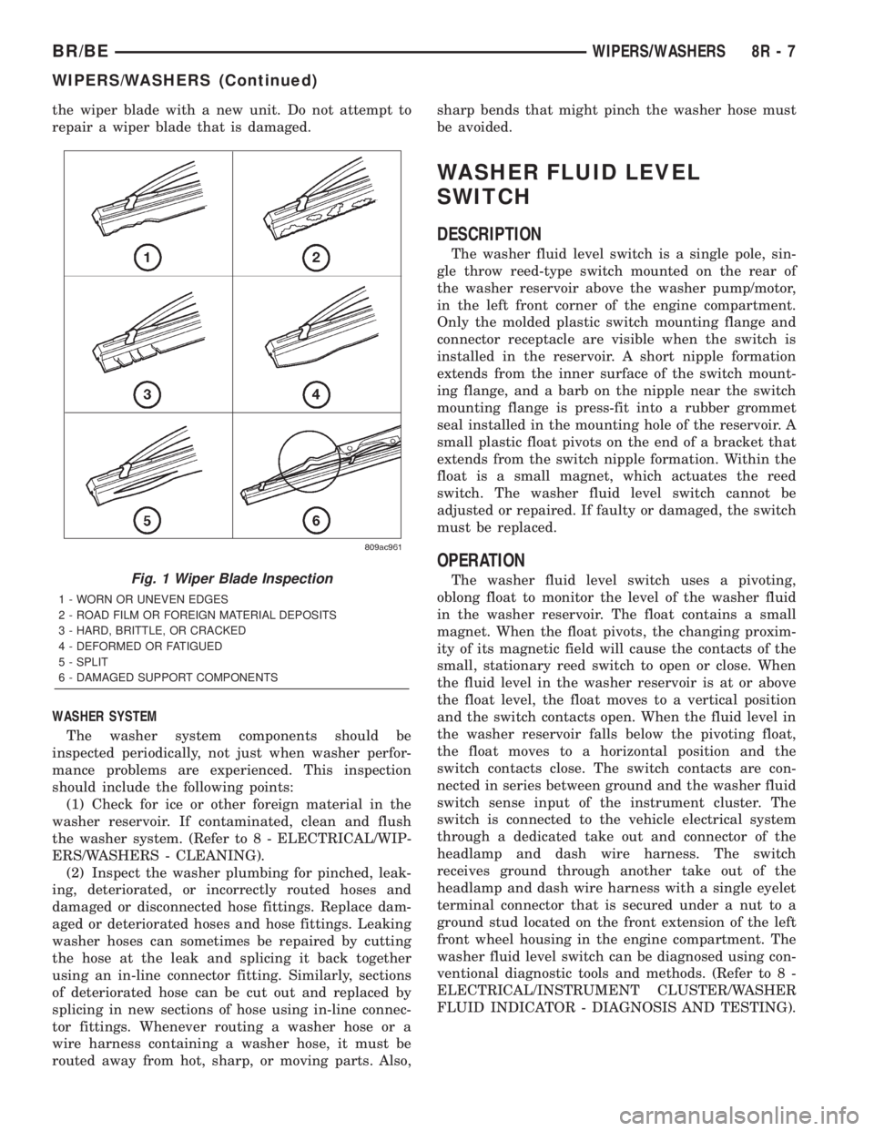
rioration (Fig. 1). If the wiper blades or squeegees
are contaminated with any foreign material, clean
them and the glass as required. (Refer to 8 - ELEC-
TRICAL/WIPERS/WASHERS - CLEANING). After
cleaning the wiper blade and the glass, if the wiper
blade still fails to clear the glass without smearing,
streaking, chattering, hazing, or beading, replace the
wiper blade. Also, if a wiper blade is damaged or the
squeegee rubber is damaged or deteriorated, replace
8R - 6 WIPERS/WASHERSBR/BE
WIPERS/WASHERS (Continued)
Page 650 of 2255
the wiper blade with a new unit. Do not attempt to
repair a wiper blade that is damaged.
WASHER SYSTEM
The washer system components should be
inspected periodically, not just when washer perfor-
mance problems are experienced. This inspection
should include the following points:
(1) Check for ice or other foreign material in the
washer reservoir. If contaminated, clean and flush
the washer system. (Refer to 8 - ELECTRICAL/WIP-
ERS/WASHERS - CLEANING).
(2) Inspect the washer plumbing for pinched, leak-
ing, deteriorated, or incorrectly routed hoses and
damaged or disconnected hose fittings. Replace dam-
aged or deteriorated hoses and hose fittings. Leaking
washer hoses can sometimes be repaired by cutting
the hose at the leak and splicing it back together
using an in-line connector fitting. Similarly, sections
of deteriorated hose can be cut out and replaced by
splicing in new sections of hose using in-line connec-
tor fittings. Whenever routing a washer hose or a
wire harness containing a washer hose, it must be
routed away from hot, sharp, or moving parts. Also,sharp bends that might pinch the washer hose must
be avoided.
WASHER FLUID LEVEL
SWITCH
DESCRIPTION
The washer fluid level switch is a single pole, sin-
gle throw reed-type switch mounted on the rear of
the washer reservoir above the washer pump/motor,
in the left front corner of the engine compartment.
Only the molded plastic switch mounting flange and
connector receptacle are visible when the switch is
installed in the reservoir. A short nipple formation
extends from the inner surface of the switch mount-
ing flange, and a barb on the nipple near the switch
mounting flange is press-fit into a rubber grommet
seal installed in the mounting hole of the reservoir. A
small plastic float pivots on the end of a bracket that
extends from the switch nipple formation. Within the
float is a small magnet, which actuates the reed
switch. The washer fluid level switch cannot be
adjusted or repaired. If faulty or damaged, the switch
must be replaced.
OPERATION
The washer fluid level switch uses a pivoting,
oblong float to monitor the level of the washer fluid
in the washer reservoir. The float contains a small
magnet. When the float pivots, the changing proxim-
ity of its magnetic field will cause the contacts of the
small, stationary reed switch to open or close. When
the fluid level in the washer reservoir is at or above
the float level, the float moves to a vertical position
and the switch contacts open. When the fluid level in
the washer reservoir falls below the pivoting float,
the float moves to a horizontal position and the
switch contacts close. The switch contacts are con-
nected in series between ground and the washer fluid
switch sense input of the instrument cluster. The
switch is connected to the vehicle electrical system
through a dedicated take out and connector of the
headlamp and dash wire harness. The switch
receives ground through another take out of the
headlamp and dash wire harness with a single eyelet
terminal connector that is secured under a nut to a
ground stud located on the front extension of the left
front wheel housing in the engine compartment. The
washer fluid level switch can be diagnosed using con-
ventional diagnostic tools and methods. (Refer to 8 -
ELECTRICAL/INSTRUMENT CLUSTER/WASHER
FLUID INDICATOR - DIAGNOSIS AND TESTING).Fig. 1 Wiper Blade Inspection
1 - WORN OR UNEVEN EDGES
2 - ROAD FILM OR FOREIGN MATERIAL DEPOSITS
3 - HARD, BRITTLE, OR CRACKED
4 - DEFORMED OR FATIGUED
5 - SPLIT
6 - DAMAGED SUPPORT COMPONENTS
BR/BEWIPERS/WASHERS 8R - 7
WIPERS/WASHERS (Continued)