check engine DODGE RAM 2002 Service Manual PDF
[x] Cancel search | Manufacturer: DODGE, Model Year: 2002, Model line: RAM, Model: DODGE RAM 2002Pages: 2255, PDF Size: 62.07 MB
Page 414 of 2255
CHARGING
TABLE OF CONTENTS
page page
CHARGING
DESCRIPTION.........................25
OPERATION...........................25
DIAGNOSIS AND TESTING - CHARGING
SYSTEM............................25
SPECIFICATIONS
GENERATOR RATINGS.................26
SPECIFICATIONS - TORQUE -
GENERATOR/CHARGING SYSTEM........27
BATTERY TEMPERATURE SENSOR
DESCRIPTION.........................27OPERATION...........................27
REMOVAL.............................27
INSTALLATION.........................28
GENERATOR
DESCRIPTION.........................28
OPERATION...........................28
REMOVAL.............................28
INSTALLATION.........................30
VOLTAGE REGULATOR
DESCRIPTION.........................30
OPERATION...........................30
CHARGING
DESCRIPTION
The charging system consists of:
²Generator
²Electronic Voltage Regulator (EVR) circuitry
within the Powertrain Control Module (PCM)
²Ignition switch
²Battery (refer to 8, Battery for information)
²Battery temperature sensor
²Check Gauges Lamp (if equipped)
²Voltmeter (refer to 8, Instrument Panel and
Gauges for information)
²Wiring harness and connections (refer to 8, Wir-
ing Diagrams for information)
OPERATION
The charging system is turned on and off with the
ignition switch. The system is on when the engine is
running and the ASD relay is energized. When the
ASD relay is on, voltage is supplied to the ASD relay
sense circuit at the PCM. This voltage is connected
through the PCM and supplied to one of the genera-
tor field terminals (Gen. Source +) at the back of the
generator.
The amount of direct current produced by the gen-
erator is controlled by the EVR (field control) cir-
cuitry contained within the PCM. This circuitry is
connected in series with the second rotor field termi-
nal and ground.
A battery temperature sensor, located in the bat-
tery tray housing, is used to sense battery tempera-
ture. This temperature data, along with data from
monitored line voltage, is used by the PCM to vary
the battery charging rate. This is done by cycling theground path to control the strength of the rotor mag-
netic field. The PCM then compensates and regulates
generator current output accordingly.
All vehicles are equipped with On-Board Diagnos-
tics (OBD). All OBD-sensed systems, including EVR
(field control) circuitry, are monitored by the PCM.
Each monitored circuit is assigned a Diagnostic Trou-
ble Code (DTC). The PCM will store a DTC in elec-
tronic memory for certain failures it detects. Refer to
On-Board Diagnostics in 25, Emission Control Sys-
tem for more DTC information and a list of codes.
The Check Gauges Lamp (if equipped) monitors:
charging system voltage,engine coolant tempera-
ture and engine oil pressure. If an extreme condition
is indicated, the lamp will be illuminated. This is
done as reminder to check the three gauges. The sig-
nal to activate the lamp is sent via the CCD bus cir-
cuits. The lamp is located on the instrument panel.
Refer to 8, Instrument Panel and Gauges for addi-
tional information.
DIAGNOSIS AND TESTING - CHARGING
SYSTEM
The following procedures may be used to diagnose
the charging system if:
²the check gauges lamp (if equipped) is illumi-
nated with the engine running
²the voltmeter (if equipped) does not register
properly
²an undercharged or overcharged battery condi-
tion occurs.
Remember that an undercharged battery is often
caused by:
²accessories being left on with the engine not
running
BR/BECHARGING 8F - 25
Page 415 of 2255
²a faulty or improperly adjusted switch that
allows a lamp to stay on. Refer to Ignition-Off Draw
Test in 8, Battery for more information.
INSPECTION
The Powertrain Control Module (PCM) monitors
critical input and output circuits of the charging sys-
tem, making sure they are operational. A Diagnostic
Trouble Code (DTC) is assigned to each input and
output circuit monitored by the On-Board Diagnostic
(OBD) system. Some charging system circuits are
checked continuously, and some are checked only
under certain conditions.
Refer to Diagnostic Trouble Codes in; Powertrain
Control Module; Electronic Control Modules for more
DTC information. This will include a complete list of
DTC's including DTC's for the charging system.
To perform a complete test of the charging system,
refer to the appropriate Powertrain Diagnostic Proce-
dures service manual and the DRBtscan tool. Per-
form the following inspections before attaching the
scan tool.
(1) Inspect the battery condition. Refer to 8, Bat-
tery for procedures.(2) Inspect condition of battery cable terminals,
battery posts, connections at engine block, starter
solenoid and relay. They should be clean and tight.
Repair as required.
(3) Inspect all fuses in both the fuseblock and
Power Distribution Center (PDC) for tightness in
receptacles. They should be properly installed and
tight. Repair or replace as required.
(4) Inspect generator mounting bolts for tightness.
Replace or tighten bolts if required. Refer to the Gen-
erator Removal/Installation section of this group for
torque specifications.
(5) Inspect generator drive belt condition and ten-
sion. Tighten or replace belt as required. Refer to
Belt Tension Specifications in 7, Cooling System.
(6) Inspect automatic belt tensioner (if equipped).
Refer to 7, Cooling System for information.
(7) Inspect generator electrical connections at gen-
erator field, battery output, and ground terminal (if
equipped). Also check generator ground wire connec-
tion at engine (if equipped). They should all be clean
and tight. Repair as required.
SPECIFICATIONS
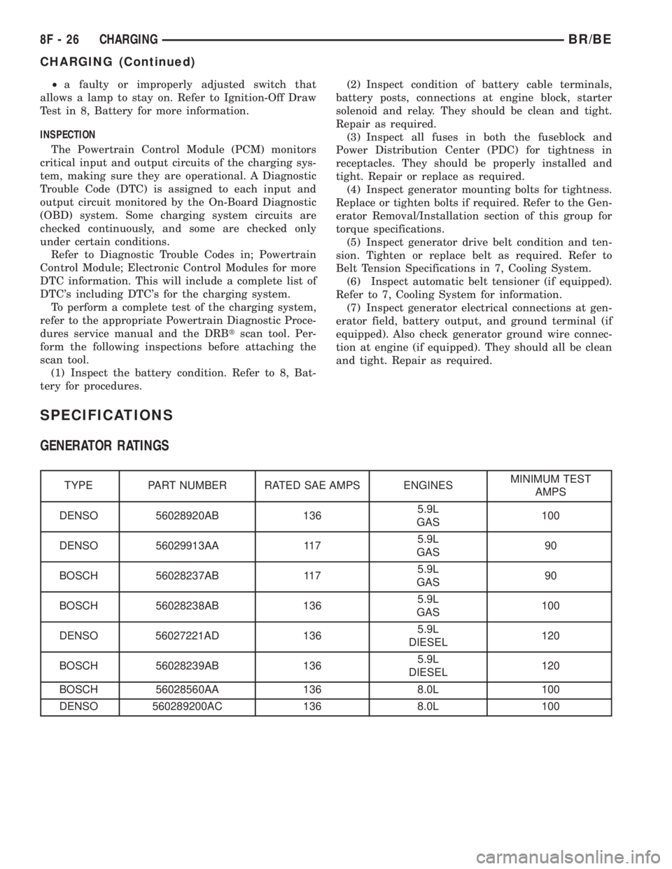
GENERATOR RATINGS
TYPE PART NUMBER RATED SAE AMPS ENGINESMINIMUM TEST
AMPS
DENSO 56028920AB 1365.9L
GAS100
DENSO 56029913AA 1175.9L
GAS90
BOSCH 56028237AB 1175.9L
GAS90
BOSCH 56028238AB 1365.9L
GAS100
DENSO 56027221AD 1365.9L
DIESEL120
BOSCH 56028239AB 1365.9L
DIESEL120
BOSCH 56028560AA 136 8.0L 100
DENSO 560289200AC 136 8.0L 100
8F - 26 CHARGINGBR/BE
CHARGING (Continued)
Page 427 of 2255
the feed of battery voltage to the starter motor, also
engaging and disengaging the starter pinion gear
with the starter ring gear.
All starter motors use an overrunning clutch and
starter pinion gear unit to engage and drive a starter
ring gear that is integral to the flywheel (manual
transmission), torque converter or torque converter
drive plate (automatic transmission) mounted on the
rear crankshaft flange.
DIAGNOSIS AND TESTING - STARTER MOTOR
Correct starter motor operation can be confirmed
by performing the following free running bench test.
This test can only be performed with starter motor
removed from vehicle. Refer to Starter Specifications
for starter motor specifications.
(1) Remove starter motor from vehicle. Refer to
Starter MotorRemoval and Installation.
(2) Mount starter motor securely in a soft-jawed
bench vise. The vise jaws should be clamped on
mounting flange of starter motor. Never clamp on
starter motor by field frame.
(3) Connect suitable volt-ampere tester and 12-volt
battery to starter motor in series, and set ammeter to
100 ampere scale (250 ampere scale for diesel engine
starters). See instructions provided by manufacturer
of volt-ampere tester being used.
(4) Install jumper wire from solenoid terminal to
solenoid battery terminal. The starter motor should
operate. If starter motor fails to operate, replace
faulty starter motor assembly.
(5) Adjust carbon pile load of tester to obtain free
running test voltage. Refer to Specifications for the
starter motor free running test voltage specifications.
(6) Note reading on ammeter and compare this
reading to free running test maximum amperage
draw. Refer to Specifications for starter motor free
running test maximum amperage draw specifica-
tions.
(7) If ammeter reading exceeds maximum amper-
age draw specification, replace faulty starter motor
assembly.
STARTER MOTOR SOLENOID
This test can only be performed with starter motor
removed from vehicle.
(1) Remove starter motor. Refer toStarter Motor
Removal and Installation.
(2) Disconnect wire from solenoid field coil termi-
nal.
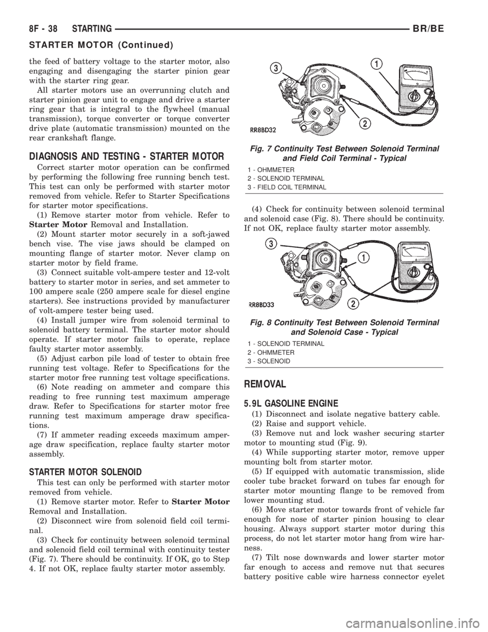
(3) Check for continuity between solenoid terminal
and solenoid field coil terminal with continuity tester
(Fig. 7). There should be continuity. If OK, go to Step
4. If not OK, replace faulty starter motor assembly.(4) Check for continuity between solenoid terminal
and solenoid case (Fig. 8). There should be continuity.
If not OK, replace faulty starter motor assembly.
REMOVAL
5.9L GASOLINE ENGINE
(1) Disconnect and isolate negative battery cable.
(2) Raise and support vehicle.
(3) Remove nut and lock washer securing starter
motor to mounting stud (Fig. 9).
(4) While supporting starter motor, remove upper
mounting bolt from starter motor.
(5) If equipped with automatic transmission, slide
cooler tube bracket forward on tubes far enough for
starter motor mounting flange to be removed from
lower mounting stud.
(6) Move starter motor towards front of vehicle far
enough for nose of starter pinion housing to clear
housing. Always support starter motor during this
process, do not let starter motor hang from wire har-
ness.
(7) Tilt nose downwards and lower starter motor
far enough to access and remove nut that secures
battery positive cable wire harness connector eyelet
Fig. 7 Continuity Test Between Solenoid Terminal
and Field Coil Terminal - Typical
1 - OHMMETER
2 - SOLENOID TERMINAL
3 - FIELD COIL TERMINAL
Fig. 8 Continuity Test Between Solenoid Terminal
and Solenoid Case - Typical
1 - SOLENOID TERMINAL
2 - OHMMETER
3 - SOLENOID
8F - 38 STARTINGBR/BE
STARTER MOTOR (Continued)
Page 430 of 2255
STARTER MOTOR RELAY
DESCRIPTION
The starter relay is an electromechanical device
that switches battery current to the pull-in coil of the
starter solenoid when ignition switch is turned to
Start position. The starter relay is located in the
Power Distribution Center (PDC) in the engine com-
partment. See PDC cover for relay identification and
location.
The starter relay is a International Standards
Organization (ISO) relay. Relays conforming to ISO
specifications have common physical dimensions, cur-
rent capacities, terminal patterns, and terminal func-
tions.
The starter relay cannot be repaired or adjusted
and, if faulty or damaged, it must be replaced.
OPERATION
The ISO relay consists of an electromagnetic coil, a
resistor or diode, and three (two fixed and one mov-
able) electrical contacts. The movable (common feed)
relay contact is held against one of the fixed contacts
(normally closed) by spring pressure. When electro-
magnetic coil is energized, it draws the movable con-
tact away from normally closed fixed contact, and
holds it against the other (normally open) fixed con-
tact.
When electromagnetic coil is de-energized, spring
pressure returns movable contact to normally closed
position. The resistor or diode is connected in parallel
with electromagnetic coil within relay, and helps to
dissipate voltage spikes produced when coil is de-en-
ergized.
DIAGNOSIS AND TESTING - STARTER RELAY
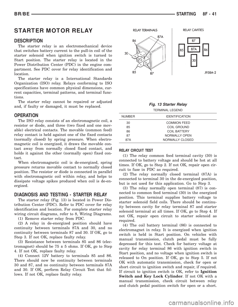
The starter relay (Fig. 13) is located in Power Dis-
tribution Center (PDC). Refer to PDC cover for relay
identification and location. For complete starter relay
wiring circuit diagrams, refer to 8, Wiring Diagrams.
(1) Remove starter relay from PDC.
(2) A relay in de-energized position should have
continuity between terminals 87A and 30, and no
continuity between terminals 87 and 30. If OK, go to
Step 3. If not OK, replace faulty relay.
(3) Resistance between terminals 85 and 86 (elec-
tromagnet) should be 75 5 ohms. If OK, go to Step
4. If not OK, replace faulty relay.
(4) Connect 12V battery to terminals 85 and 86.
There should now be continuity between terminals
30 and 87, and no continuity between terminals 87A
and 30. If OK, perform Relay Circuit Test that fol-
lows. If not OK, replace faulty relay.RELAY CIRCUIT TEST
(1) The relay common feed terminal cavity (30) is
connected to battery voltage and should be hot at all
times. If OK, go to Step 2. If not OK, repair open cir-
cuit to fuse in PDC as required.
(2) The relay normally closed terminal (87A) is
connected to terminal 30 in the de-energized position,
but is not used for this application. Go to Step 3.
(3) The relay normally open terminal (87) is con-
nected to common feed terminal (30) in the energized
position. This terminal supplies battery voltage to
starter solenoid field coils. There should be continu-
ity between cavity for relay terminal 87 and starter
solenoid terminal at all times. If OK, go to Step 4. If
not OK, repair open circuit to starter solenoid as
required.
(4) The coil battery terminal (86) is connected to
electromagnet in relay. It is energized when ignition
switch is held in Start position. On vehicles with
manual transmission, clutch pedal must be fully
depressed for this test. Check for battery voltage at
cavity for relay terminal 86 with ignition switch in
Start position, and no voltage when ignition switch is
released to On position. If OK, go to Step 5. If not
OK with automatic transmission, check for open or
short circuit to ignition switch and repair, if required.
If circuit to ignition switch is OK, refer toIgnition
Switch and Key Lock Cylinder. If not OK with a
manual transmission, check circuit between relay
and clutch pedal position switch for open or a short.
Fig. 13 Starter Relay
TERMINAL LEGEND
NUMBER IDENTIFICATION
30 COMMON FEED
85 COIL GROUND
86 COIL BATTERY
87 NORMALLY OPEN
87A NORMALLY CLOSED
BR/BESTARTING 8F - 41
Page 447 of 2255
B(+) to heated seat module circuit to the heated seat
module as required.
(4) The coil battery terminal (86) is connected to
the electromagnet in the relay. It is connected to bat-
tery voltage and should be hot at all times. Check for
battery voltage at the cavity for relay terminal 86. If
OK, go to Step 5. If not OK, repair the open circuit to
the fused B(+) fuse in the PDC as required.
(5) The coil ground terminal (85) is connected to
the electromagnet in the relay. It is grounded by the
premium version of the Central Timer Module (CTM)
in response to an engine speed message received over
the Chrysler Collision Detection (CCD) data bus from
the Powertrain Control Module (PCM) when the
engine is running. Check for continuity between the
cavity for relay terminal 85 and the heated seat relay
control circuit cavity of the CTM wire harness con-
nector. There should be continuity at all times. If OK,
use a DRBIIItscan tool and the proper diagnostic
procedures manual to test the operation of the CTM
and CCD data bus. If not OK, repair the open heated
seat relay control circuit as required.
REMOVAL
(1) Disconnect and isolate the battery negative
cable.
(2) Remove the fuse access panel by inserting a
finger in the finger recess molded into the panel and
then pulling the panel sharply away from the left
outboard end of the instrument panel.
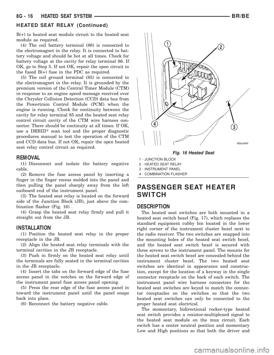
(3) The heated seat relay is located on the forward
side of the Junction Block (JB), just above the com-
bination flasher (Fig. 16) .
(4) Grasp the heated seat relay firmly and pull it
straight out from the JB.
INSTALLATION
(1) Position the heated seat relay in the proper
receptacle in the JB.
(2) Align the heated seat relay terminals with the
terminal cavities in the JB receptacle.
(3) Push in firmly on the heated seat relay until
the terminals are fully seated in the terminal cavities
in the JB receptacle.
(4) Insert the tabs on the forward edge of the fuse
access panel in the notches on the forward edge of
the instrument panel fuse access panel opening.
(5) Press the rear edge of the fuse access panel in
toward the instrument panel until the panel snaps
back into place.
(6) Reconnect the battery negative cable.
PASSENGER SEAT HEATER
SWITCH
DESCRIPTION
The heated seat switches are both mounted in a
heated seat switch bezel (Fig. 17), which replaces the
standard equipment cubby bin located in the lower
right corner of the instrument cluster bezel next to
the radio receiver. The two switches are snapped into
the mounting holes of the heated seat switch bezel,
and the heated seat switch bezel is secured with
three screws to the instrument panel. The mounts for
the heated seat switch bezel are concealed behind the
instrument cluster bezel. The two heated seat
switches are identical in appearance and construc-
tion, except for the location of a keyway in the single
connector receptacle on the back of each switch. The
instrument panel wire harness connectors for the
heated seat switches are keyed to match the connec-
tor receptacles on the switches so that the two
heated seat switches can only be connected to the
proper heated seat electrical.
The momentary, bidirectional rocker-type heated
seat switch provides a resistor-multiplexed signal to
the heated seat module on the mux circuit. Each
switch has a center neutral position and momentary
Low and High positions so that both the driver and
Fig. 16 Heated Seat
1 - JUNCTION BLOCK
2 - HEATED SEAT RELAY
3 - INSTRUMENT PANEL
4 - COMBINATION FLASHER
8G - 16 HEATED SEAT SYSTEMBR/BE
HEATED SEAT RELAY (Continued)
Page 453 of 2255
ELECTRICAL/VEHICLE THEFT SECURITY - GEN-
ERAL INFORMATION) for more information on the
VTSS. (Refer to 8 - ELECTRICAL/POWER LOCKS -
GENERAL INFORMATION) for more information on
the RKE system.
HORN
DESCRIPTION
The standard single, low-note, electromagnetic dia-
phragm-type horn is secured with a bracket to the
right front fender wheel house extension in the
engine compartment. The high-note horn for the
optional dual-note horn system is connected in paral-
lel with and secured with a bracket just forward of
the low-note horn. Each horn is grounded through its
wire harness connector and circuit to a ground splice
joint connector, and receives battery feed through the
closed contacts of the horn relay.
The horns cannot be repaired or adjusted and, if
faulty or damaged, they must be individually
replaced.
OPERATION
Within the two halves of the molded plastic horn
housing are a flexible diaphragm, a plunger, an elec-
tromagnetic coil and a set of contact points. The dia-
phragm is secured in suspension around its
perimeter by the mating surfaces of the horn hous-
ing. The plunger is secured to the center of the dia-
phragm and extends into the center of the
electromagnet. The contact points control the current
flow through the electromagnet.
When the horn is energized, electrical current
flows through the closed contact points to the electro-
magnet. The resulting electromagnetic field draws
the plunger and diaphragm toward it until that
movement mechanically opens the contact points.
When the contact points open, the electromagnetic
field collapses allowing the plunger and diaphragm to
return to their relaxed positions and closing the con-
tact points again. This cycle continues repeating at a
very rapid rate producing the vibration and move-
ment of air that creates the sound that is directed
through the horn outlet.
DIAGNOSIS AND TESTING - HORN
For complete circuit diagrams, refer to the appro-
priate wiring information. The wiring information
includes wiring diagrams, proper wire and connector
repair procedures, details of wire harness routing
and retention, connector pin-out information and
location views for the various wire harness connec-
tors, splices and grounds.(1) Disconnect the wire harness connector(s) from
the horn connector receptacle(s). Measure the resis-
tance between the ground circuit cavity of the horn(s)
wire harness connector(s) and a good ground. There
should be no measurable resistance. If OK, go to Step
2. If not OK, repair the open ground circuit to ground
as required.
(2) Check for battery voltage at the horn relay out-
put circuit cavity of the horn(s) wire harness connec-
tor(s). There should be zero volts. If OK, go to Step 3.
If not OK, repair the shorted horn relay output cir-
cuit or replace the faulty horn relay as required.
(3) Depress the horn switch. There should now be
battery voltage at the horn relay output circuit cavity
of the horn(s) wire harness connector(s). If OK,
replace the faulty horn(s). If not OK, repair the open
horn relay output circuit to the horn relay as
required.
REMOVAL
(1) Disconnect and isolate the battery negative
cable.
(2) Disconnect the wire harness connector(s) from
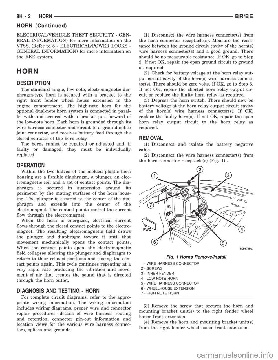
the horn connector receptacle(s) (Fig. 1) .
(3) Remove the screw that secures the horn and
mounting bracket unit(s) to the right fender wheel
house front extension.
(4) Remove the horn and mounting bracket unit(s)
from the right fender wheel house front extension.
Fig. 1 Horns Remove/Install
1 - WIRE HARNESS CONNECTOR
2 - SCREWS
3 - INNER FENDER
4 - LOW NOTE HORN
5 - WIRE HARNESS CONNECTOR
6 - WHEELHOUSE EXTENSION
7 - HIGH NOTE HORN
8H - 2 HORNBR/BE
HORN (Continued)
Page 466 of 2255
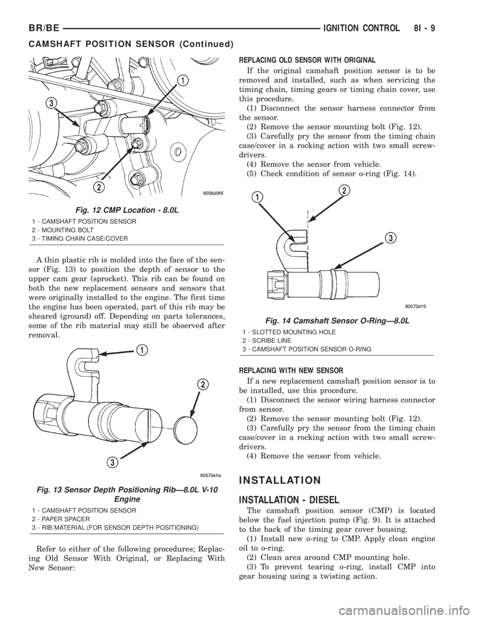
A thin plastic rib is molded into the face of the sen-
sor (Fig. 13) to position the depth of sensor to the
upper cam gear (sprocket). This rib can be found on
both the new replacement sensors and sensors that
were originally installed to the engine. The first time
the engine has been operated, part of this rib may be
sheared (ground) off. Depending on parts tolerances,
some of the rib material may still be observed after
removal.
Refer to either of the following procedures; Replac-
ing Old Sensor With Original, or Replacing With
New Sensor:REPLACING OLD SENSOR WITH ORIGINAL
If the original camshaft position sensor is to be
removed and installed, such as when servicing the
timing chain, timing gears or timing chain cover, use
this procedure.
(1) Disconnect the sensor harness connector from
the sensor.
(2) Remove the sensor mounting bolt (Fig. 12).
(3) Carefully pry the sensor from the timing chain
case/cover in a rocking action with two small screw-
drivers.
(4) Remove the sensor from vehicle.
(5) Check condition of sensor o-ring (Fig. 14).
REPLACING WITH NEW SENSOR
If a new replacement camshaft position sensor is to
be installed, use this procedure.
(1) Disconnect the sensor wiring harness connector
from sensor.
(2) Remove the sensor mounting bolt (Fig. 12).
(3) Carefully pry the sensor from the timing chain
case/cover in a rocking action with two small screw-
drivers.
(4) Remove the sensor from vehicle.
INSTALLATION
INSTALLATION - DIESEL
The camshaft position sensor (CMP) is located
below the fuel injection pump (Fig. 9). It is attached
to the back of the timing gear cover housing.
(1) Install new o-ring to CMP. Apply clean engine
oil to o-ring.
(2) Clean area around CMP mounting hole.
(3) To prevent tearing o-ring, install CMP into
gear housing using a twisting action.
Fig. 12 CMP Location - 8.0L
1 - CAMSHAFT POSITION SENSOR
2 - MOUNTING BOLT
3 - TIMING CHAIN CASE/COVER
Fig. 13 Sensor Depth Positioning RibÐ8.0L V-10
Engine
1 - CAMSHAFT POSITION SENSOR
2 - PAPER SPACER
3 - RIB MATERIAL (FOR SENSOR DEPTH POSITIONING)
Fig. 14 Camshaft Sensor O-RingÐ8.0L
1 - SLOTTED MOUNTING HOLE
2 - SCRIBE LINE
3 - CAMSHAFT POSITION SENSOR O-RING
BR/BEIGNITION CONTROL 8I - 9
CAMSHAFT POSITION SENSOR (Continued)
Page 470 of 2255
INSTALLATION
If engine has been cranked while distributor is
removed, establish the relationship between distribu-
tor shaft and number one piston position as follows:
Rotate crankshaft in a clockwise direction, as
viewed from front, until number one cylinder piston
is at top of compression stroke (compression should
be felt on finger with number one spark plug
removed). Then continue to slowly rotate engine
clockwise until indicating mark (Fig. 18) is aligned to
0 degree (TDC) mark on timing chain cover.
(1) Clean top of cylinder block for a good seal
between distributor base and block.
(2) Lightly oil the rubber o-ring seal on the distrib-
utor housing.
(3) Install rotor to distributor shaft.
(4) Position distributor into engine to its original
position. Engage tongue of distributor shaft with slot
in distributor oil pump drive gear. Position rotor to
the number one spark plug cable position.
(5) Install distributor holddown clamp and clamp
bolt. Do not tighten bolt at this time.
(6) Rotate the distributor housing until rotor is
aligned to CYL. NO. 1 alignment mark on the cam-
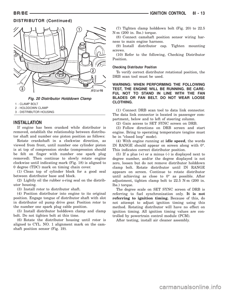
shaft position sensor (Fig. 19).(7) Tighten clamp holddown bolt (Fig. 20) to 22.5
N´m (200 in. lbs.) torque.
(8) Connect camshaft position sensor wiring har-
ness to main engine harness.
(9) Install distributor cap. Tighten mounting
screws.
(10) Refer to the following, Checking Distributor
Position.
Checking Distributor Position
To verify correct distributor rotational position, the
DRB scan tool must be used.
WARNING: WHEN PERFORMING THE FOLLOWING
TEST, THE ENGINE WILL BE RUNNING. BE CARE-
FUL NOT TO STAND IN LINE WITH THE FAN
BLADES OR FAN BELT. DO NOT WEAR LOOSE
CLOTHING.
(1) Connect DRB scan tool to data link connector.
The data link connector is located in passenger com-
partment, below and to left of steering column.
(2) Gain access to SET SYNC screen on DRB.
(3) Follow directions on DRB screen and start
engine. Bring to operating temperature (engine must
be in ªclosed loopº mode).
(4) With engine running atidle speed, the words
IN RANGE should appear on screen along with 0É.
This indicates correct distributor position.
(5) If a plus (+) or a minus (-) is displayed next to
degree number, and/or the degree displayed is not
zero, loosen but do not remove distributor holddown
clamp bolt. Rotate distributor until IN RANGE
appears on screen. Continue to rotate distributor
until achieving as close to 0É as possible. After
adjustment, tighten clamp bolt to 22.5 N´m (200 in.
lbs.) torque.
The degree scale on SET SYNC screen of DRB is
referring to fuel synchronization only.It is not
referring to ignition timing.Because of this, do
not attempt to adjust ignition timing using this
method. Rotating distributor will have no effect on
ignition timing. All ignition timing values are con-
trolled by powertrain control module (PCM).
After testing, install air cleaner assembly.
Fig. 20 Distributor Holddown Clamp
1 - CLAMP BOLT
2 - HOLDDOWN CLAMP
3 - DISTRIBUTOR HOUSING
BR/BEIGNITION CONTROL 8I - 13
DISTRIBUTOR (Continued)
Page 473 of 2255
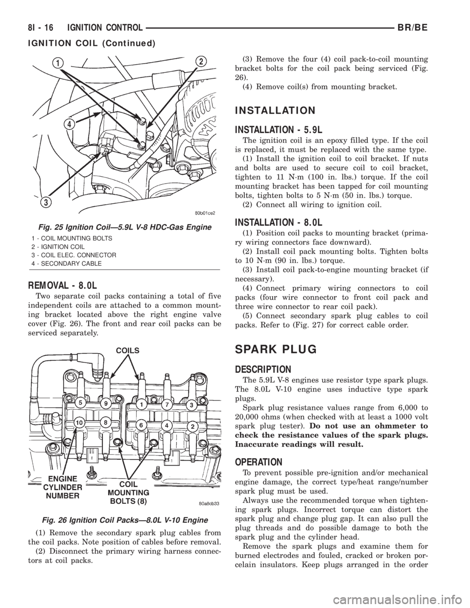
REMOVAL - 8.0L
Two separate coil packs containing a total of five
independent coils are attached to a common mount-
ing bracket located above the right engine valve
cover (Fig. 26). The front and rear coil packs can be
serviced separately.
(1) Remove the secondary spark plug cables from
the coil packs. Note position of cables before removal.
(2) Disconnect the primary wiring harness connec-
tors at coil packs.(3) Remove the four (4) coil pack-to-coil mounting
bracket bolts for the coil pack being serviced (Fig.
26).
(4) Remove coil(s) from mounting bracket.
INSTALLATION
INSTALLATION - 5.9L
The ignition coil is an epoxy filled type. If the coil
is replaced, it must be replaced with the same type.
(1) Install the ignition coil to coil bracket. If nuts
and bolts are used to secure coil to coil bracket,
tighten to 11 N´m (100 in. lbs.) torque. If the coil
mounting bracket has been tapped for coil mounting
bolts, tighten bolts to 5 N´m (50 in. lbs.) torque.
(2) Connect all wiring to ignition coil.
INSTALLATION - 8.0L
(1) Position coil packs to mounting bracket (prima-
ry wiring connectors face downward).
(2) Install coil pack mounting bolts. Tighten bolts
to 10 N´m (90 in. lbs.) torque.
(3) Install coil pack-to-engine mounting bracket (if
necessary).
(4) Connect primary wiring connectors to coil
packs (four wire connector to front coil pack and
three wire connector to rear coil pack).
(5) Connect secondary spark plug cables to coil
packs. Refer to (Fig. 27) for correct cable order.
SPARK PLUG
DESCRIPTION
The 5.9L V-8 engines use resistor type spark plugs.
The 8.0L V-10 engine uses inductive type spark
plugs.
Spark plug resistance values range from 6,000 to
20,000 ohms (when checked with at least a 1000 volt
spark plug tester).Do not use an ohmmeter to
check the resistance values of the spark plugs.
Inaccurate readings will result.
OPERATION
To prevent possible pre-ignition and/or mechanical
engine damage, the correct type/heat range/number
spark plug must be used.
Always use the recommended torque when tighten-
ing spark plugs. Incorrect torque can distort the
spark plug and change plug gap. It can also pull the
plug threads and do possible damage to both the
spark plug and the cylinder head.
Remove the spark plugs and examine them for
burned electrodes and fouled, cracked or broken por-
celain insulators. Keep plugs arranged in the order
Fig. 25 Ignition CoilÐ5.9L V-8 HDC-Gas Engine
1 - COIL MOUNTING BOLTS
2 - IGNITION COIL
3 - COIL ELEC. CONNECTOR
4 - SECONDARY CABLE
Fig. 26 Ignition Coil PacksÐ8.0L V-10 Engine
8I - 16 IGNITION CONTROLBR/BE
IGNITION COIL (Continued)
Page 477 of 2255
(2) Prior to removing the spark plug, spray com-
pressed air around the spark plug hole and the area
around the spark plug. This will help prevent foreign
material from entering the combustion chamber.
(3) Remove the spark plug using a quality socket
with a rubber or foam insert.
(4) Inspect the spark plug condition. Refer to
Spark Plug Condition in the Diagnostics and Testing
section of this group.
CLEANING
The plugs may be cleaned using commercially
available spark plug cleaning equipment. After clean-
ing, file center electrode flat with a small point file or
jewelers file before adjusting gap.
CAUTION: Never use a motorized wire wheel brush
to clean spark plugs. Metallic deposits will remain
on spark plug insulator and will cause plug misfire.
INSTALLATION
Special care should be taken when installing spark
plugs into the cylinder head spark plug wells. Be
sure the plugs do not drop into the plug wells as elec-
trodes can be damaged.
Always tighten spark plugs to the specified torque.
Over tightening can cause distortion resulting in a
change in the spark plug gap or a cracked porcelain
insulator.
When replacing the spark plug and ignition coil
cables, route the cables correctly and secure them in
the appropriate retainers. Failure to route the cables
properly can cause the radio to reproduce ignition
noise. It could cause cross ignition of the spark plugs
or short circuit the cables to ground.
(1) Start the spark plug into the cylinder head by
hand to avoid cross threading.
(2) Tighten spark plugs to 35-41 N´m (26-30 ft.
lbs.) torque.
(3) Install spark plug cables over spark plugs.
SPARK PLUG CABLE
DESCRIPTION
Spark plug cables are sometimes referred to as sec-
ondary ignition wires.
OPERATION
The spark plug cables transfer electrical current
from the ignition coil(s) and/or distributor, to individ-
ual spark plugs at each cylinder. The resistive spark
plug cables are of nonmetallic construction. The
cables provide suppression of radio frequency emis-
sions from the ignition system.
DIAGNOSIS AND TESTING - SPARK PLUG
CABLES
Cable routing is important on certain engines. To
prevent possible ignition crossfire, be sure the cables
are clipped into the plastic routing looms. Try to pre-
vent any one cable from contacting another. Before
removing cables, note their original location and
routing. Never allow one cable to be twisted around
another.
Check the spark plug cable connections for good
contact at the coil(s), distributor cap towers, and
spark plugs. Terminals should be fully seated. The
insulators should be in good condition and should fit
tightly on the coil, distributor and spark plugs. Spark
plug cables with insulators that are cracked or torn
must be replaced.
Clean high voltage ignition cables with a cloth
moistened with a non-flammable solvent. Wipe the
cables dry. Check for brittle or cracked insulation.
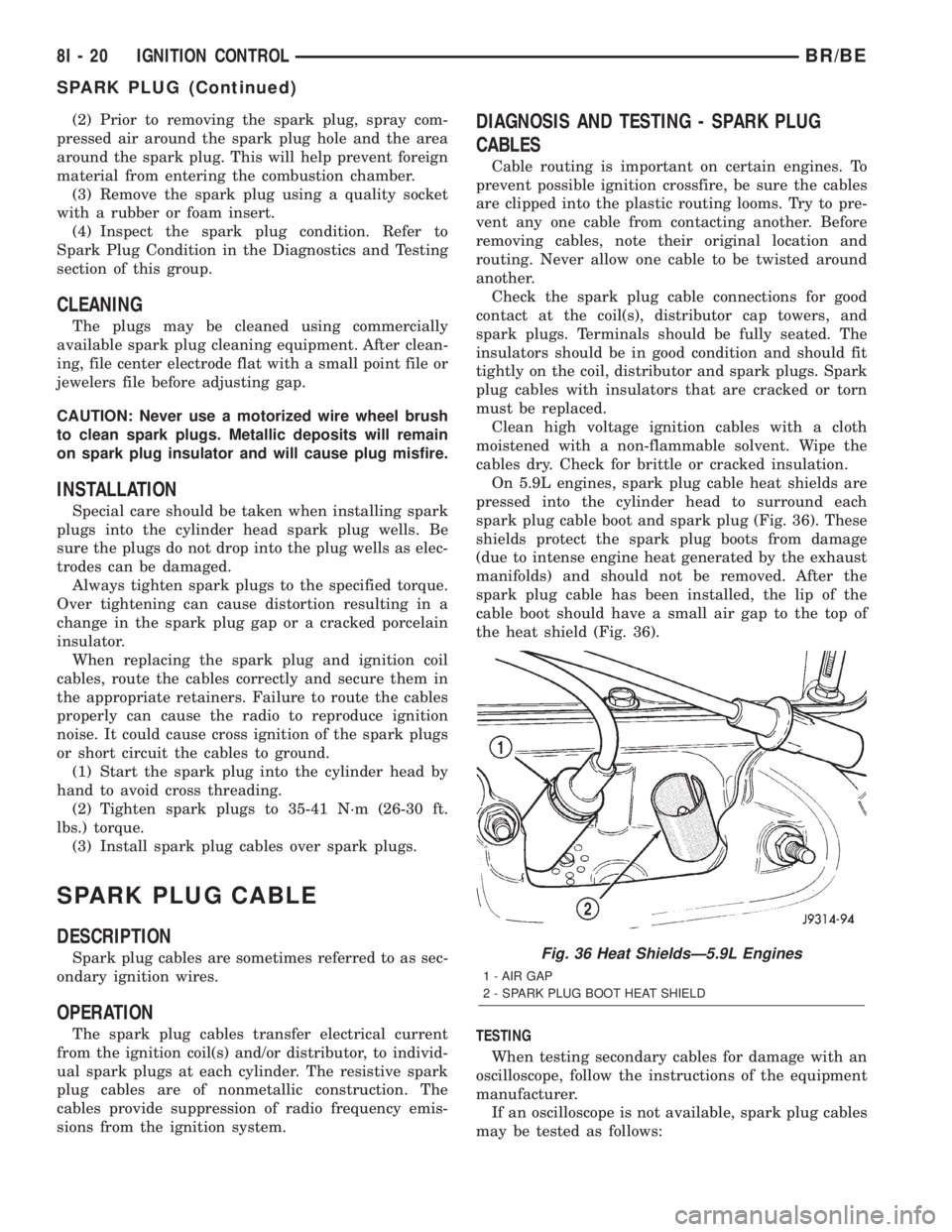
On 5.9L engines, spark plug cable heat shields are
pressed into the cylinder head to surround each
spark plug cable boot and spark plug (Fig. 36). These
shields protect the spark plug boots from damage
(due to intense engine heat generated by the exhaust
manifolds) and should not be removed. After the
spark plug cable has been installed, the lip of the
cable boot should have a small air gap to the top of
the heat shield (Fig. 36).
TESTING
When testing secondary cables for damage with an
oscilloscope, follow the instructions of the equipment
manufacturer.
If an oscilloscope is not available, spark plug cables
may be tested as follows:
Fig. 36 Heat ShieldsÐ5.9L Engines
1 - AIR GAP
2 - SPARK PLUG BOOT HEAT SHIELD
8I - 20 IGNITION CONTROLBR/BE
SPARK PLUG (Continued)