check engine DODGE RAM 2002 Service Repair Manual
[x] Cancel search | Manufacturer: DODGE, Model Year: 2002, Model line: RAM, Model: DODGE RAM 2002Pages: 2255, PDF Size: 62.07 MB
Page 626 of 2255
Once the speed control has been disengaged,
depressing the RES/ACCEL switch (when speed is
greater than 30 mph) restores the vehicle to the tar-
get speed that was stored in the ECM.
While the speed control is engaged, the driver can
increase the vehicle speed by depressing the RES/AC-
CEL switch. The new target speed is stored in the
ECM when the RES/ACCEL is released. The ECM
also has a9tap-up9feature in which vehicle speed
increases at a rate of approximately 2 mph for each
momentary switch activation of the RES/ACCEL
switch.
A ªtap downº feature is used to decelerate without
disengaging the speed control system. To decelerate
from an existing recorded target speed, momentarily
depress the COAST switch. For each switch activa-
tion, speed will be lowered approximately 1 mph.
DIAGNOSIS AND TESTING
DIAGNOSIS AND TESTING - VACUUM SUPPLY
TEST
Gas Powered Engines
On gasoline powered engines: actual engine vac-
uum, a vacuum reservoir, a one-way check valve and
vacuum lines are used to supply vacuum to the speed
control servo.
(1) Disconnect vacuum hose at speed control servo
and install a vacuum gauge into the disconnected
hose.
(2) Start engine and observe gauge at idle. Vac-
uum gauge should read at least ten inches of mer-
cury.
(3) If vacuum is less than ten inches of mercury,
determine source of leak. Check vacuum line to
engine for leaks. Also check actual engine intake
manifold vacuum. If manifold vacuum does not meet
this requirement, check for poor engine performance
and repair as necessary.
(4) If vacuum line to engine is not leaking, check
for leak at vacuum reservoir. To locate and gain
access to reservoir, refer to Vacuum Reservoir Remov-
al/Installation in this group. Disconnect vacuum line
at reservoir and connect a hand-operated vacuum
pump to reservoir fitting. Apply vacuum. Reservoir
vacuum should not bleed off. If vacuum is being lost,
replace reservoir.
(5) Verify operation of one-way check valve and
check it for leaks.
(a) Locate one-way check valve. The valve is
located in vacuum line between vacuum reservoirand engine vacuum source. Disconnect vacuum
hoses (lines) at each end of valve.
(b) Connect a hand-operated vacuum pump to
reservoir end of check valve. Apply vacuum. Vac-
uum should not bleed off. If vacuum is being lost,
replace one-way check valve.
(c) Connect a hand-operated vacuum pump to
vacuum source end of check valve. Apply vacuum.
Vacuum should flow through valve. If vacuum is
not flowing, replace one-way check valve. Seal the
fitting at opposite end of valve with a finger and
apply vacuum. If vacuum will not hold, diaphragm
within check valve has ruptured. Replace valve.
Diesel Engines With Automatic Trans.
On diesel powered engines equipped with an auto-
matic transmission: an engine driven vacuum pump,
a one-way check valve and vacuum lines are used to
supply vacuum to the speed control servo. A vacuum
reservoir is not used.
(1) Disconnect vacuum hose at speed control servo
and install a vacuum gauge into the disconnected
hose.
(2) Start engine and observe gauge at idle. For
vacuum testing and vacuum specifications, refer to
Vacuum Pump OutputÐDiesel Engine in 9, Engines.
(3) If vacuum pump output is OK, determine other
source of leak. Check all vacuum lines to: speed con-
trol servo, engine vacuum pump and heating/air con-
ditioning system for leaks.
(4) Verify operation of one-way check valve and
check it for leaks.
(a) Locate one-way check valve. The valve is
located in vacuum line between speed control servo
and engine vacuum pump. Disconnect vacuum
hoses (lines) at each end of valve.
(b) Connect a hand-operated vacuum pump to
reservoir end of check valve. Apply vacuum. Vac-
uum should not bleed off. If vacuum is being lost,
replace one-way check valve.
(c) Connect a hand-operated vacuum pump to
vacuum source end of check valve. Apply vacuum.
Vacuum should flow through valve. If vacuum is
not flowing, replace one-way check valve. Seal the
fitting at opposite end of valve with a finger and
apply vacuum. If vacuum will not hold, diaphragm
within check valve has ruptured. Replace valve.
Diesel Engine With Manual Trans.
Vacuum is not used for any part of the speed con-
trol system if equipped with a diesel engine and a
manual transmission.
BR/BESPEED CONTROL 8P - 3
SPEED CONTROL (Continued)
Page 627 of 2255
DIAGNOSIS AND TESTING - ROAD TEST
Perform a vehicle road test to verify reports of
speed control system malfunction. The road test
should include attention to the speedometer.
If a road test verifies a system problem and the
speedometer operates properly, check for:
²A Diagnostic Trouble Code (DTC). If a DTC
exists, conduct tests per the Powertrain Diagnostic
Procedures service manual.
²A misadjusted brake (stop) lamp switch. This
could also cause an intermittent problem.
²Loose, damaged or corroded electrical connec-
tions at the servo. Corrosion should be removed from
electrical terminals and a light coating of Mopart
MultiPurpose Grease, or equivalent, applied.²Leaking vacuum reservoir.
²Loose or leaking vacuum hoses or connections.
²Defective one-way vacuum check valve.
²Secure attachment of both ends of the speed con-
trol servo cable.
²Smooth operation of throttle linkage and throttle
body air valve.
²Failed speed control servo. Do the servo vacuum
test.
CAUTION: When test probing for voltage or conti-
nuity at electrical connectors, care must be taken
not to damage connector, terminals or seals. If
these components are damaged, intermittent or
complete system failure may occur.
SPECIFICATIONS
TORQUE - SPEED CONTROL SYSTEM
DESCRIPTION N´m Ft. Lbs. In. Lbs.
Servo Mounting Bracket
Nuts8.5 - 75
Switch Module Mounting
Screws3-26
Vacuum Reservoir
Mounting Screws2.2 -
20
CABLE
DESCRIPTION
The speed control servo cable is connected between
the speed control vacuum servo diaphragm and the
throttle body control linkage.
OPERATION
This cable causes the throttle control linkage to
open or close the throttle valve in response to move-
ment of the vacuum servo diaphragm.
REMOVAL
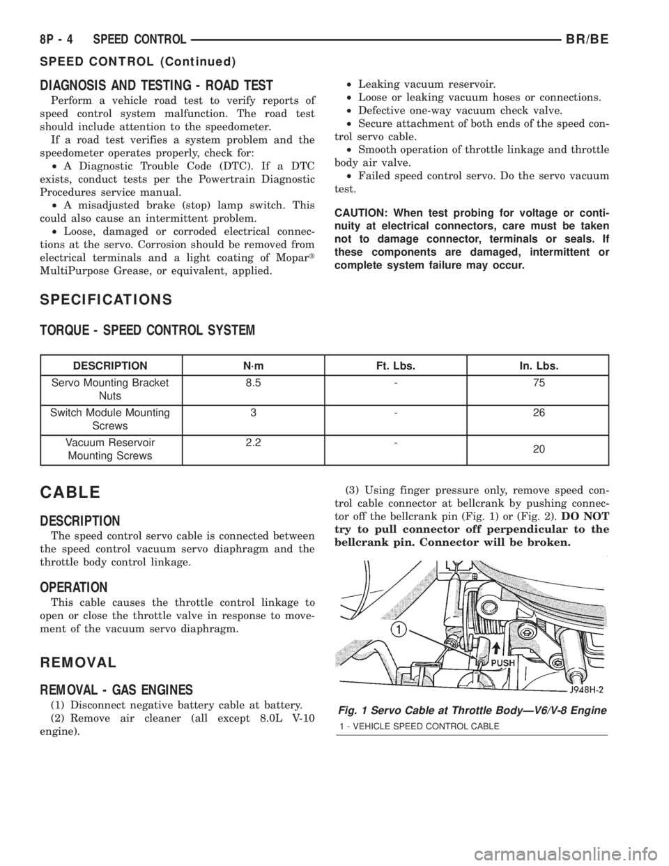
REMOVAL - GAS ENGINES
(1) Disconnect negative battery cable at battery.
(2) Remove air cleaner (all except 8.0L V-10
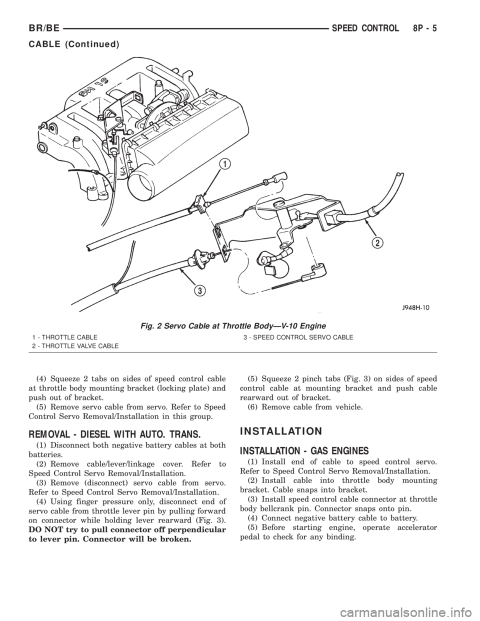
engine).(3) Using finger pressure only, remove speed con-
trol cable connector at bellcrank by pushing connec-
tor off the bellcrank pin (Fig. 1) or (Fig. 2).DO NOT
try to pull connector off perpendicular to the
bellcrank pin. Connector will be broken.Fig. 1 Servo Cable at Throttle BodyÐV6/V-8 Engine
1 - VEHICLE SPEED CONTROL CABLE
8P - 4 SPEED CONTROLBR/BE
SPEED CONTROL (Continued)
Page 628 of 2255
(4) Squeeze 2 tabs on sides of speed control cable
at throttle body mounting bracket (locking plate) and
push out of bracket.
(5) Remove servo cable from servo. Refer to Speed
Control Servo Removal/Installation in this group.
REMOVAL - DIESEL WITH AUTO. TRANS.
(1) Disconnect both negative battery cables at both
batteries.
(2) Remove cable/lever/linkage cover. Refer to
Speed Control Servo Removal/Installation.
(3) Remove (disconnect) servo cable from servo.
Refer to Speed Control Servo Removal/Installation.
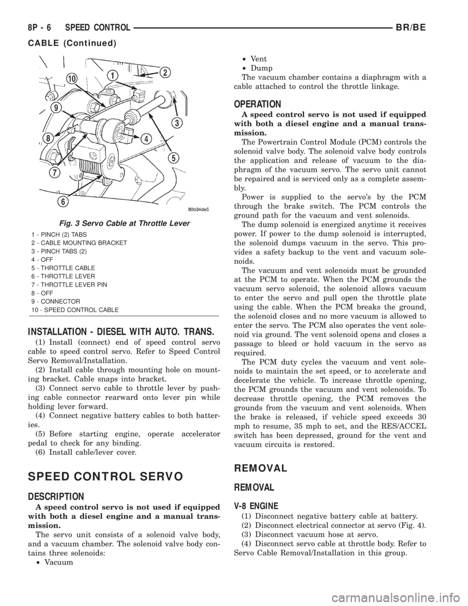
(4) Using finger pressure only, disconnect end of
servo cable from throttle lever pin by pulling forward
on connector while holding lever rearward (Fig. 3).
DO NOT try to pull connector off perpendicular
to lever pin. Connector will be broken.(5) Squeeze 2 pinch tabs (Fig. 3) on sides of speed
control cable at mounting bracket and push cable
rearward out of bracket.
(6) Remove cable from vehicle.
INSTALLATION
INSTALLATION - GAS ENGINES
(1) Install end of cable to speed control servo.
Refer to Speed Control Servo Removal/Installation.
(2) Install cable into throttle body mounting
bracket. Cable snaps into bracket.
(3) Install speed control cable connector at throttle
body bellcrank pin. Connector snaps onto pin.
(4) Connect negative battery cable to battery.
(5) Before starting engine, operate accelerator
pedal to check for any binding.
Fig. 2 Servo Cable at Throttle BodyÐV-10 Engine
1 - THROTTLE CABLE
2 - THROTTLE VALVE CABLE3 - SPEED CONTROL SERVO CABLE
BR/BESPEED CONTROL 8P - 5
CABLE (Continued)
Page 629 of 2255
INSTALLATION - DIESEL WITH AUTO. TRANS.
(1) Install (connect) end of speed control servo
cable to speed control servo. Refer to Speed Control
Servo Removal/Installation.
(2) Install cable through mounting hole on mount-
ing bracket. Cable snaps into bracket.
(3) Connect servo cable to throttle lever by push-
ing cable connector rearward onto lever pin while
holding lever forward.
(4) Connect negative battery cables to both batter-
ies.
(5) Before starting engine, operate accelerator
pedal to check for any binding.
(6) Install cable/lever cover.
SPEED CONTROL SERVO
DESCRIPTION
A speed control servo is not used if equipped
with both a diesel engine and a manual trans-
mission.
The servo unit consists of a solenoid valve body,
and a vacuum chamber. The solenoid valve body con-
tains three solenoids:
²Vacuum²Vent
²Dump
The vacuum chamber contains a diaphragm with a
cable attached to control the throttle linkage.
OPERATION
A speed control servo is not used if equipped
with both a diesel engine and a manual trans-
mission.
The Powertrain Control Module (PCM) controls the
solenoid valve body. The solenoid valve body controls
the application and release of vacuum to the dia-
phragm of the vacuum servo. The servo unit cannot
be repaired and is serviced only as a complete assem-
bly.
Power is supplied to the servo's by the PCM
through the brake switch. The PCM controls the
ground path for the vacuum and vent solenoids.
The dump solenoid is energized anytime it receives
power. If power to the dump solenoid is interrupted,
the solenoid dumps vacuum in the servo. This pro-
vides a safety backup to the vent and vacuum sole-
noids.
The vacuum and vent solenoids must be grounded
at the PCM to operate. When the PCM grounds the
vacuum servo solenoid, the solenoid allows vacuum
to enter the servo and pull open the throttle plate
using the cable. When the PCM breaks the ground,
the solenoid closes and no more vacuum is allowed to
enter the servo. The PCM also operates the vent sole-
noid via ground. The vent solenoid opens and closes a
passage to bleed or hold vacuum in the servo as
required.
The PCM duty cycles the vacuum and vent sole-
noids to maintain the set speed, or to accelerate and
decelerate the vehicle. To increase throttle opening,
the PCM grounds the vacuum and vent solenoids. To
decrease throttle opening, the PCM removes the
grounds from the vacuum and vent solenoids. When
the brake is released, if vehicle speed exceeds 30
mph to resume, 35 mph to set, and the RES/ACCEL
switch has been depressed, ground for the vent and
vacuum circuits is restored.
REMOVAL
REMOVAL
V-8 ENGINE
(1) Disconnect negative battery cable at battery.
(2) Disconnect electrical connector at servo (Fig. 4).
(3) Disconnect vacuum hose at servo.
(4) Disconnect servo cable at throttle body. Refer to
Servo Cable Removal/Installation in this group.
Fig. 3 Servo Cable at Throttle Lever
1 - PINCH (2) TABS
2 - CABLE MOUNTING BRACKET
3 - PINCH TABS (2)
4 - OFF
5 - THROTTLE CABLE
6 - THROTTLE LEVER
7 - THROTTLE LEVER PIN
8 - OFF
9 - CONNECTOR
10 - SPEED CONTROL CABLE
8P - 6 SPEED CONTROLBR/BE
CABLE (Continued)
Page 634 of 2255
INSTALLATION
INSTALLATION
V-8 ENGINE
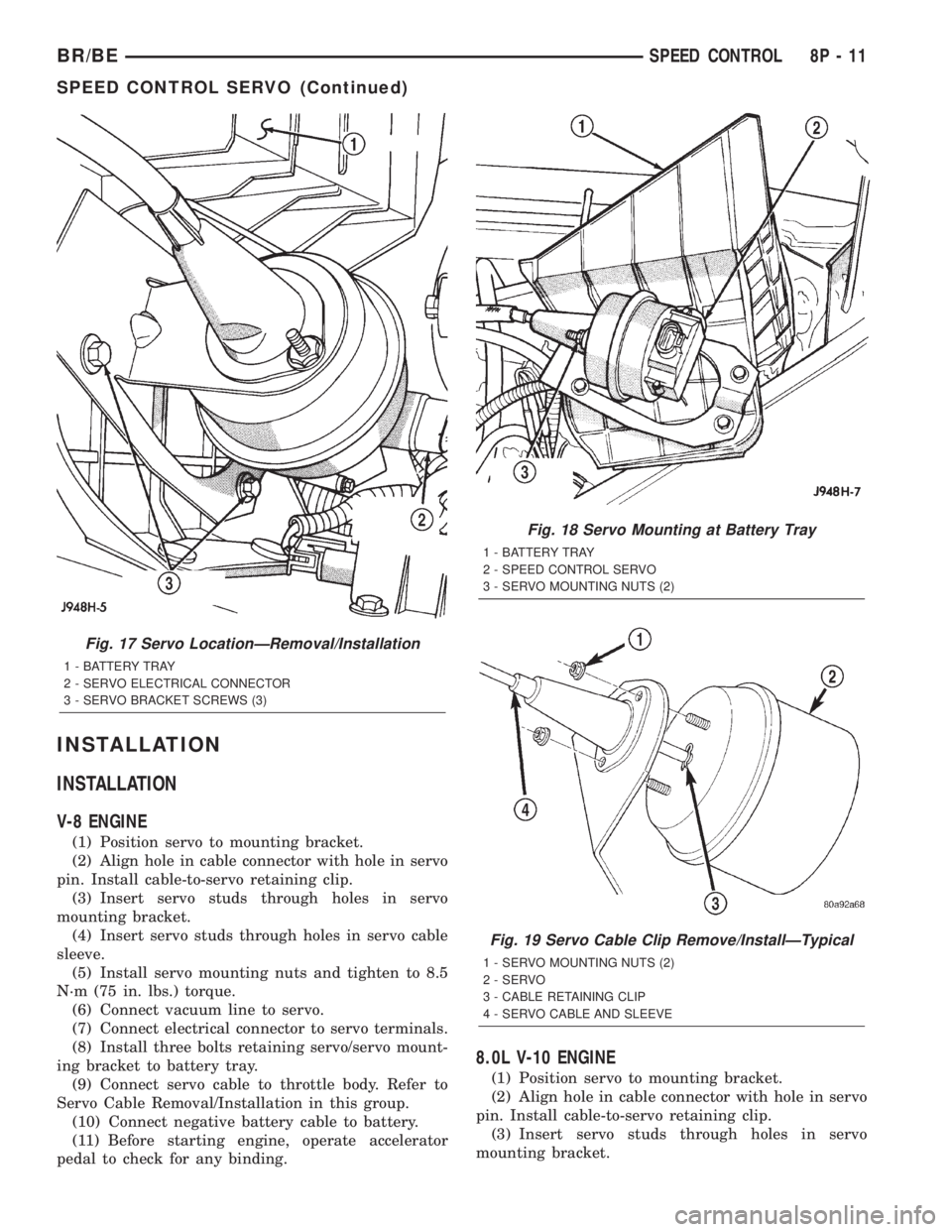
(1) Position servo to mounting bracket.
(2) Align hole in cable connector with hole in servo
pin. Install cable-to-servo retaining clip.
(3) Insert servo studs through holes in servo
mounting bracket.
(4) Insert servo studs through holes in servo cable
sleeve.
(5) Install servo mounting nuts and tighten to 8.5
N´m (75 in. lbs.) torque.
(6) Connect vacuum line to servo.
(7) Connect electrical connector to servo terminals.
(8) Install three bolts retaining servo/servo mount-
ing bracket to battery tray.
(9) Connect servo cable to throttle body. Refer to
Servo Cable Removal/Installation in this group.
(10) Connect negative battery cable to battery.
(11) Before starting engine, operate accelerator
pedal to check for any binding.
8.0L V-10 ENGINE
(1) Position servo to mounting bracket.
(2) Align hole in cable connector with hole in servo
pin. Install cable-to-servo retaining clip.
(3) Insert servo studs through holes in servo
mounting bracket.
Fig. 17 Servo LocationÐRemoval/Installation
1 - BATTERY TRAY
2 - SERVO ELECTRICAL CONNECTOR
3 - SERVO BRACKET SCREWS (3)
Fig. 18 Servo Mounting at Battery Tray
1 - BATTERY TRAY
2 - SPEED CONTROL SERVO
3 - SERVO MOUNTING NUTS (2)
Fig. 19 Servo Cable Clip Remove/InstallÐTypical
1 - SERVO MOUNTING NUTS (2)
2 - SERVO
3 - CABLE RETAINING CLIP
4 - SERVO CABLE AND SLEEVE
BR/BESPEED CONTROL 8P - 11
SPEED CONTROL SERVO (Continued)
Page 635 of 2255
(4) Insert servo studs through holes in servo cable
sleeve.
(5) Install servo mounting nuts and tighten to 8.5
N´m (75 in. lbs.) torque.
(6) Connect vacuum line to servo.
(7) Connect electrical connector to servo terminals.
(8) Connect servo cable to throttle body. Refer to
Servo Cable Removal/Installation in this group.
(9) Install battery tray. Tighten all battery tray
mounting hardware to 16 N´m (140 in. lbs.) torque.
(10) Position battery into battery tray.
(11) If equipped, install battery heat shield.
(12) Install battery holddown clamp. Tighten bolt
to 4 N´m (35 in. lbs.) torque.
(13) Connect positive battery cable to battery.
(14) Connect negative battery cable to battery.
(15) Before starting engine, operate accelerator
pedal to check for any binding.
INSTALLATION - DIESEL WITH AUTO. TRANS.
(1) Position servo to mounting bracket.
(2) Align hole in cable connector with hole in servo
pin. Install cable-to-servo retaining clip.
(3) Insert servo studs through holes in servo
mounting bracket.
(4) Insert servo studs through holes in servo cable
sleeve.
(5) Install servo mounting nuts and tighten to 8.5
N´m (75 in. lbs.) torque.
(6) Connect vacuum line to servo.
(7) Connect electrical connector to servo terminals.
(8) Connect servo cable to throttle lever by push-
ing cable connector rearward onto lever pin while
holding lever forward.
(9) Install battery tray. Tighten all battery tray
mounting hardware to 16 N´m (140 in. lbs.) torque.
(10) Position battery into battery tray.
(11) If equipped, install battery heat shield.
(12) Install battery holddown clamp. Tighten bolt
to 4 N´m (35 in. lbs.) torque.
(13) Connect positive battery cable to battery.
(14) Connect negative battery cables to both bat-
teries.
(15) Before starting engine, operate accelerator
pedal to check for any binding.
(16) Install cable/lever cover.
SWITCH
DESCRIPTION
Gas Engines and Diesel With Auto. Trans.
There are two separate switch pods that operate
the speed control system. The steering-wheel-
mounted switches use multiplexed circuits to provideinputs to the Powertrain Control Module (PCM) for
ON, OFF, RESUME, ACCELERATE, SET, DECEL
and CANCEL modes. Refer to the owner's manual for
more information on speed control switch functions
and setting procedures.
The individual switches cannot be repaired. If one
switch fails, the entire switch module must be
replaced.
Diesel With Manual Trans.
There are two separate switch pods that operate
the speed control system. The steering-wheel-
mounted switches use multiplexed circuits to provide
inputs to the Engine Control Module (ECM) for ON,
OFF, RESUME, ACCELERATE, SET, DECEL and
CANCEL modes. Refer to the owner's manual for
more information on speed control switch functions
and setting procedures.
The individual switches cannot be repaired. If one
switch fails, the entire switch module must be
replaced.
OPERATION
Gas Engines and Diesel With Auto. Trans.
When speed control is selected by depressing the
ON, OFF switch, the Powertrain Control Module
(PCM) allows a set speed to be stored in its RAM for
speed control. To store a set speed, depress the SET
switch while the vehicle is moving at a speed
between approximately 35 and 85 mph. In order for
the speed control to engage, the brakes cannot be
applied, nor can the gear selector be indicating the
transmission is in Park or Neutral.
The speed control can be disengaged manually by:
²Stepping on the brake pedal.
²Depressing the OFF switch.
²Depressing the CANCEL switch.
The speed control can be disengaged also by any of
the following conditions:
²An indication of Park or Neutral.
²The vehicle speed signal increases at a rate of
10 mph per second (indicates that the co-efficient of
friction between the road surface and tires is
extremely low).
²Depressing the clutch pedal.
²Excessive engine rpm (indicates that the trans-
mission may be in a low gear).
²The vehicle speed signal decreases at a rate of
10 mph per second (indicates that the vehicle may
have decelerated at an extremely high rate).
²If the actual speed is not within 20 mph of the
set speed.
The previous disengagement conditions are pro-
grammed for added safety.
8P - 12 SPEED CONTROLBR/BE
SPEED CONTROL SERVO (Continued)
Page 637 of 2255
INSTALLATION
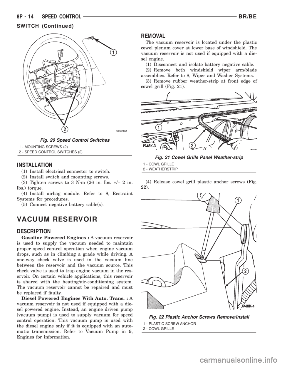
(1) Install electrical connector to switch.
(2) Install switch and mounting screws.
(3) Tighten screws to 3 N´m (26 in. lbs. +/± 2 in.
lbs.) torque.
(4) Install airbag module. Refer to 8, Restraint
Systems for procedures.
(5) Connect negative battery cable(s).
VACUUM RESERVOIR
DESCRIPTION
Gasoline Powered Engines :A vacuum reservoir
is used to supply the vacuum needed to maintain
proper speed control operation when engine vacuum
drops, such as in climbing a grade while driving. A
one-way check valve is used in the vacuum line
between the reservoir and the vacuum source. This
check valve is used to trap engine vacuum in the res-
ervoir. On certain vehicle applications, this reservoir
is shared with the heating/air-conditioning system.
The vacuum reservoir cannot be repaired and must
be replaced if faulty.
Diesel Powered Engines With Auto. Trans. :A
vacuum reservoir is not used if equipped with a die-
sel powered engine. Instead, an engine driven pump
(vacuum pump) is used to supply vacuum for speed
control operation. This vacuum pump is used with
the diesel engine only if it is equipped with an auto-
matic transmission. Refer to Vacuum Pump in 9,
Engines for information.
REMOVAL
The vacuum reservoir is located under the plastic
cowel plenum cover at lower base of windshield. The
vacuum reservoir is not used if equipped with a die-
sel engine.
(1) Disconnect and isolate battery negative cable.
(2) Remove both windshield wiper arm/blade
assemblies. Refer to 8, Wiper and Washer Systems.
(3) Remove rubber weather-strip at front edge of
cowel grill (Fig. 21).
(4) Release cowel grill plastic anchor screws (Fig.
22).
Fig. 20 Speed Control Switches
1 - MOUNTING SCREWS (2)
2 - SPEED CONTROL SWITCHES (2)
Fig. 21 Cowel Grille Panel Weather-strip
1 - COWL GRILLE
2 - WEATHERSTRIP
Fig. 22 Plastic Anchor Screws Remove/Install
1 - PLASTIC SCREW ANCHOR
2 - COWL GRILLE
8P - 14 SPEED CONTROLBR/BE
SWITCH (Continued)
Page 642 of 2255
POWER-UP MODE
When the armed VTSS senses that the battery has
been disconnected and reconnected, it enters its pow-
er-up mode. In the power-up mode the alarm system
remains armed following a battery failure or discon-
nect. If the VTSS was armed prior to a battery dis-
connect or failure, the technician or vehicle operator
will have to actively or passively disarm the alarm
system after the battery is reconnected. The pow-
er-up mode will also apply if the battery goes dead
while the system is armed, and battery jump-starting
is attempted. The engine no-run feature will prevent
the engine from starting until the alarm system has
been actively or passively disarmed. The VTSS will
be armed until the technician or vehicle operator has
actively or passively disarmed the alarm system. If
the VTSS is in the disarmed mode prior to a battery
disconnect or failure, it will remain disarmed after
the battery is reconnected or replaced, or if jump-
starting is attempted.
TAMPER ALERT
The VTSS tamper alert feature will sound the horn
three times upon disarming, if the alarm was trig-
gered and has since timed-out (about fifteen min-
utes). This feature alerts the vehicle operator that
the VTSS alarm was activated while the vehicle was
unattended.
DIAGNOSIS AND TESTING - VEHICLE THEFT
SECURITY SYSTEM
The VTSS-related hard wired inputs to and out-
puts from the high-line or premium Central Timer
Module (CTM) may be diagnosed and tested using
conventional diagnostic tools and procedures. Refer
to the appropriate wiring information. The wiring
information includes wiring diagrams, proper wire
and connector repair procedures, further details on
wire harness routing and retention, as well as pin-
out and location views for the various wire harness
connectors, splices and grounds.
However, conventional diagnostic methods may not
prove conclusive in the diagnosis of the CTM, the
Powertrain Control Module (PCM), or the Chrysler
Collision Detection (CCD) data bus network. In order
to obtain conclusive testing of the VTSS, the CTM,
the PCM, and the CCD data bus network must also
be checked. The most reliable, efficient, and accurate
means to diagnose the VTSS requires the use of a
DRBIIItscan tool. Refer to the appropriate diagnos-
tic information. The DRBIIItscan tool can provide
confirmation that the CCD data bus network is func-
tional, that all of the electronic modules are sending
and receiving the proper messages over the CCD
data bus, and that these modules are receiving the
proper hard wired inputs and responding with theproper hard wired outputs needed to perform their
functions. See the ªVehicle Theft Security Systemº
menu item on the DRBIIItscan tool.
WARNING: ON VEHICLES EQUIPPED WITH AIR-
BAGS, DISABLE THE AIRBAG SYSTEM BEFORE
ATTEMPTING ANY STEERING WHEEL, STEERING
COLUMN, OR INSTRUMENT PANEL COMPONENT
DIAGNOSIS OR SERVICE. DISCONNECT AND ISO-
LATE THE BATTERY NEGATIVE (GROUND) CABLE,
THEN WAIT TWO MINUTES FOR THE AIRBAG SYS-
TEM CAPACITOR TO DISCHARGE BEFORE PER-
FORMING FURTHER DIAGNOSIS OR SERVICE. THIS
IS THE ONLY SURE WAY TO DISABLE THE AIRBAG
SYSTEM. FAILURE TO TAKE THE PROPER PRE-
CAUTIONS COULD RESULT IN ACCIDENTAL AIR-
BAG DEPLOYMENT AND POSSIBLE PERSONAL
INJURY.
VTSS INDICATOR
DESCRIPTION
The Vehicle Theft Security System (VTSS) indica-
tor consists of a red Light-Emitting Diode (LED)
located on the electronic circuit board of the Compass
Mini-Trip Computer (CMTC) within the overhead
console. The LED extends through a hole in the
CMTC lens located near the forward end of the over-
head console housing near the windshield.
The VTSS indicator cannot be adjusted or repaired
and, if faulty or damaged, the entire CMTC unit
must be replaced. (Refer to 8 - ELECTRICAL/OVER-
HEAD CONSOLE/COMPASS/MINI-TRIP COM-
PUTER - DESCRIPTION).
OPERATION
The Vehicle Theft Security System (VTSS) indica-
tor gives a visible indication of the VTSS arming sta-
tus. One side of Light-Emitting Diode (LED) in the
VTSS indicator is connected to battery current
through a fused B(+) circuit and a fuse in the Junc-
tion Block (JB), so the indicator remains functional
regardless of the ignition switch position. The other
side of the LED is hard wired to the Central Timer
Module (CTM), which controls the operation of the
VTSS indicator by pulling this side of the LED cir-
cuit to ground. When the VTSS arming is in
progress, the CTM will flash the LED rapidly on and
off for about fifteen seconds. When the VTSS has
been successfully armed, the CTM will flash the LED
on and off continually at a much slower rate until
the VTSS has been disarmed. The VTSS indicator
can be diagnosed using conventional diagnostic tools
and methods.
BR/BEVEHICLE THEFT SECURITY 8Q - 3
VEHICLE THEFT SECURITY (Continued)
Page 650 of 2255
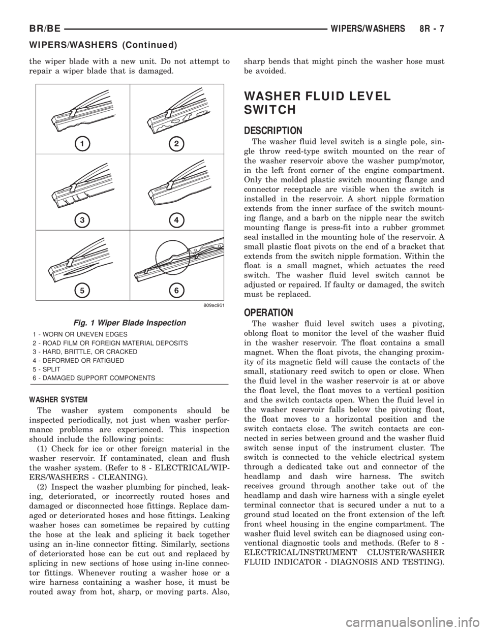
the wiper blade with a new unit. Do not attempt to
repair a wiper blade that is damaged.
WASHER SYSTEM
The washer system components should be
inspected periodically, not just when washer perfor-
mance problems are experienced. This inspection
should include the following points:
(1) Check for ice or other foreign material in the
washer reservoir. If contaminated, clean and flush
the washer system. (Refer to 8 - ELECTRICAL/WIP-
ERS/WASHERS - CLEANING).
(2) Inspect the washer plumbing for pinched, leak-
ing, deteriorated, or incorrectly routed hoses and
damaged or disconnected hose fittings. Replace dam-
aged or deteriorated hoses and hose fittings. Leaking
washer hoses can sometimes be repaired by cutting
the hose at the leak and splicing it back together
using an in-line connector fitting. Similarly, sections
of deteriorated hose can be cut out and replaced by
splicing in new sections of hose using in-line connec-
tor fittings. Whenever routing a washer hose or a
wire harness containing a washer hose, it must be
routed away from hot, sharp, or moving parts. Also,sharp bends that might pinch the washer hose must
be avoided.
WASHER FLUID LEVEL
SWITCH
DESCRIPTION
The washer fluid level switch is a single pole, sin-
gle throw reed-type switch mounted on the rear of
the washer reservoir above the washer pump/motor,
in the left front corner of the engine compartment.
Only the molded plastic switch mounting flange and
connector receptacle are visible when the switch is
installed in the reservoir. A short nipple formation
extends from the inner surface of the switch mount-
ing flange, and a barb on the nipple near the switch
mounting flange is press-fit into a rubber grommet
seal installed in the mounting hole of the reservoir. A
small plastic float pivots on the end of a bracket that
extends from the switch nipple formation. Within the
float is a small magnet, which actuates the reed
switch. The washer fluid level switch cannot be
adjusted or repaired. If faulty or damaged, the switch
must be replaced.
OPERATION
The washer fluid level switch uses a pivoting,
oblong float to monitor the level of the washer fluid
in the washer reservoir. The float contains a small
magnet. When the float pivots, the changing proxim-
ity of its magnetic field will cause the contacts of the
small, stationary reed switch to open or close. When
the fluid level in the washer reservoir is at or above
the float level, the float moves to a vertical position
and the switch contacts open. When the fluid level in
the washer reservoir falls below the pivoting float,
the float moves to a horizontal position and the
switch contacts close. The switch contacts are con-
nected in series between ground and the washer fluid
switch sense input of the instrument cluster. The
switch is connected to the vehicle electrical system
through a dedicated take out and connector of the
headlamp and dash wire harness. The switch
receives ground through another take out of the
headlamp and dash wire harness with a single eyelet
terminal connector that is secured under a nut to a
ground stud located on the front extension of the left
front wheel housing in the engine compartment. The
washer fluid level switch can be diagnosed using con-
ventional diagnostic tools and methods. (Refer to 8 -
ELECTRICAL/INSTRUMENT CLUSTER/WASHER
FLUID INDICATOR - DIAGNOSIS AND TESTING).Fig. 1 Wiper Blade Inspection
1 - WORN OR UNEVEN EDGES
2 - ROAD FILM OR FOREIGN MATERIAL DEPOSITS
3 - HARD, BRITTLE, OR CRACKED
4 - DEFORMED OR FATIGUED
5 - SPLIT
6 - DAMAGED SUPPORT COMPONENTS
BR/BEWIPERS/WASHERS 8R - 7
WIPERS/WASHERS (Continued)
Page 669 of 2255
DESCRIPTION - SECTION IDENTIFICATION AND
INFORMATION
The wiring diagrams are grouped into individual
sections. If a component is most likely found in a par-
ticular group, it will be shown complete (all wires,
connectors, and pins) within that group. For exam-
ple, the Auto Shutdown Relay is most likely to be
found in Group 30, so it is shown there complete. It
can, however, be shown partially in another group if
it contains some associated wiring.
Splice diagrams in Section 8W-70 show the entire
splice and provide references to other sections the
splices serves. Section 8W-70 only contains splice dia-
grams that are not shown in their entirety some-
where else in the wiring diagrams.
Section 8W-80 shows each connector and the cir-
cuits involved with that connector. The connectors
are identified using the name/number on the dia-
gram pages.
WIRING SECTION CHART
GROUP TOPIC
8W-01 thru
8W-09General information and Diagram
Overview
8W-10 thru
8W-19Main Sources of Power and
Vehicle Grounding
8W-20 thru
8W-29Starting and Charging
8W-30 thru
8W-39Powertrain/Drivetrain Systems
GROUP TOPIC
8W-40 thru
8W-49Body Electrical items and A/C
8W-50 thru
8W-59Exterior Lighting, Wipers and
Trailer Tow
8W-60 thru
8W-69Power Accessories
8W-70 Splice Information
8W-80 Connector Pin Outs
8W-91 Connector, Ground and Splice
Locations
DESCRIPTION - CONNECTOR, GROUND AND
SPLICE INFORMATION
CAUTION: Not all connectors are serviced. Some
connectors are serviced only with a harness. A typ-
ical example might be the Supplemental Restraint
System connectors. Always check parts availability
before attempting a repair.
IDENTIFICATION
In-line connectors are identified by a number, as
follows:
²In-line connectors located in the engine compart-
ment are C100 series numbers
²In-line connectors located in the Instrument
Panel area are C200 series numbers.
²In-line connectors located in the body are C300
series numbers.
²Jumper harness connectors are C400 series
numbers.
²Grounds and ground connectors are identified
with a ªGº and follow the same series numbering as
the in-line connectors.
²Splices are identified with an ªSº and follow the
same series numbering as the in-line connectors.
²Component connectors are identified by the com-
ponent name instead of a number. Multiple connec-
tors on a component use a C1, C2, etc. identifier.
LOCATIONS
Section 8W-91 contains connector/ground/splice
location illustrations. The illustrations contain the
connector name (or number)/ground number/splice
number and component identification. Connector/
ground/splice location charts in section 8W-91 refer-
ence the figure numbers of the illustrations.
The abbreviation T/O is used in the component
location section to indicate a point in which the wir-
ing harness branches out to a component. The abbre-
viation N/S means Not Shown in the illustrations
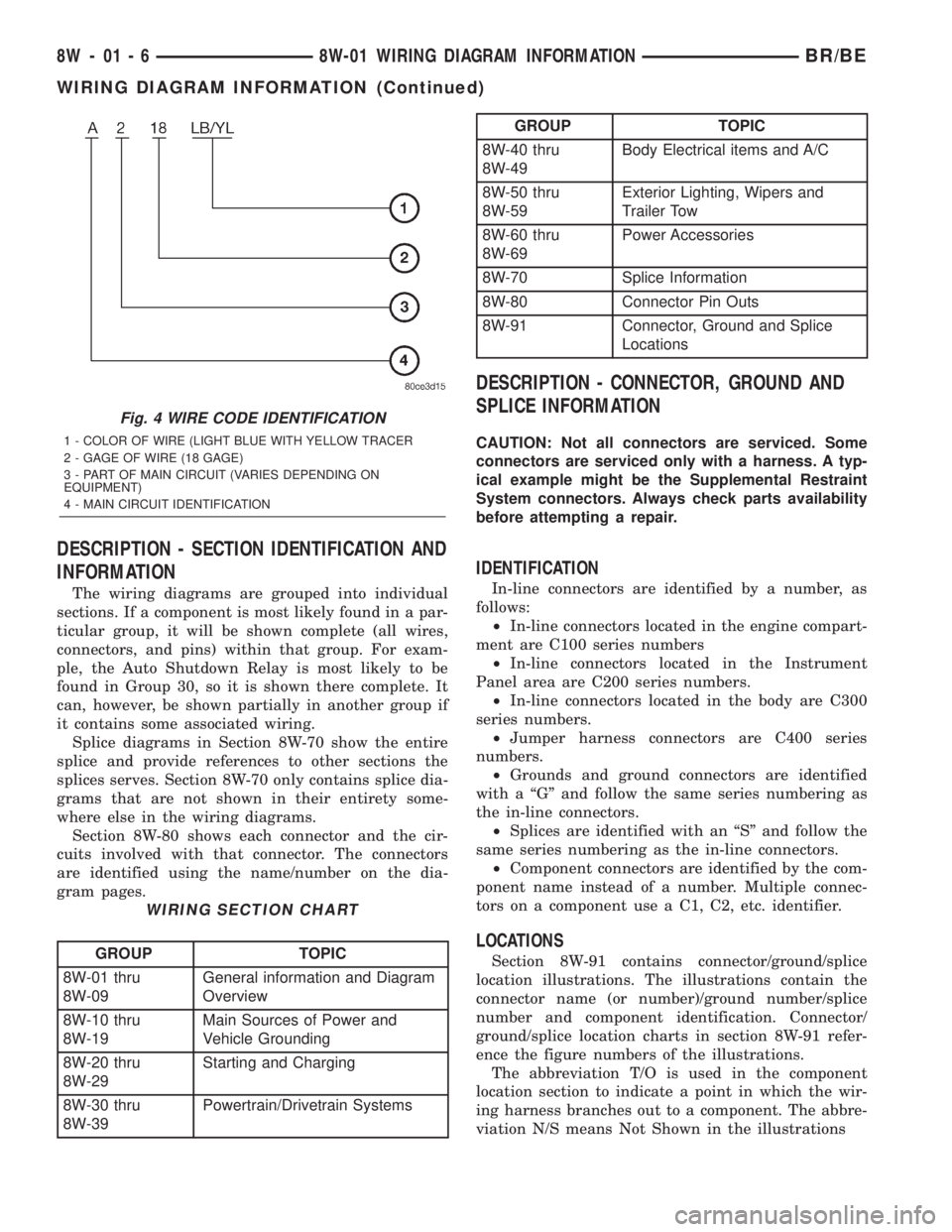
Fig. 4 WIRE CODE IDENTIFICATION
1 - COLOR OF WIRE (LIGHT BLUE WITH YELLOW TRACER
2 - GAGE OF WIRE (18 GAGE)
3 - PART OF MAIN CIRCUIT (VARIES DEPENDING ON
EQUIPMENT)
4 - MAIN CIRCUIT IDENTIFICATION
8W - 01 - 6 8W-01 WIRING DIAGRAM INFORMATIONBR/BE
WIRING DIAGRAM INFORMATION (Continued)