check engine DODGE RAM 2002 Service Owners Manual
[x] Cancel search | Manufacturer: DODGE, Model Year: 2002, Model line: RAM, Model: DODGE RAM 2002Pages: 2255, PDF Size: 62.07 MB
Page 507 of 2255
overlay causes the ªMAINT REQDº text to appear in
amber through the translucent outer layer of the
overlay when the indicator is illuminated from
behind by a Light Emitting Diode (LED) soldered
onto the instrument cluster electronic circuit board.
The SRI is serviced as a unit with the instrument
cluster.
OPERATION
The Service Reminder Indicator (SRI) gives an
indication to the vehicle operator when engine emis-
sions maintenance procedures should be performed.
This indicator is controlled by a transistor on the
instrument cluster circuit board based upon the clus-
ter programming and electronic messages received by
the cluster from the Powertrain Control Module
(PCM) over the Chrysler Collision Detection (CCD)
data bus. The SRI Light Emitting Diode (LED)
receives battery current on the instrument cluster
electronic circuit board through the fused ignition
switch output (st-run) circuit whenever the ignition
switch is in the On or Start positions; therefore, the
LED will always be off when the ignition switch is in
any position except On or Start. The LED only illu-
minates when it is provided a path to ground by the
instrument cluster transistor. The instrument cluster
will turn on the SRI for the following reasons:
²Bulb Test- Each time the ignition switch is
turned to the On position the SRI is illuminated for
about two seconds as a bulb test.
²Service Required Lamp-On Message- Each
time the cluster receives a service required lamp-on
message from the PCM indicating that an emissions
maintenance interval has been reached, the SRI will
be illuminated. The indicator remains illuminated
until the cluster receives a service required lamp-off
message from the PCM, or until the ignition switch
is turned to the Off position, whichever occurs first.
²Actuator Test- Each time the cluster is put
through the actuator test, the SRI will be turned on
during the bulb check portion of the test to confirm
the functionality of the LED and the cluster control
circuitry.
The PCM continually monitors the vehicle speed
sensor to determine the distance the vehicle has been
driven, then sends the proper messages to the instru-
ment cluster. Once the SRI has been illuminated and
the required emissions maintenance procedures have
been completed, the PCM must be reset using a
DRBIIItscan tool before it will send the proper ser-
vice required lamp-off message to the instrument
cluster. Refer to the appropriate diagnostic informa-
tion. For further diagnosis of the SRI or the instru-
ment cluster circuitry that controls the LED, (Refer
to 8 - ELECTRICAL/INSTRUMENT CLUSTER -
DIAGNOSIS AND TESTING). For proper diagnosisof the PCM, the CCD data bus, or the message
inputs to the instrument cluster that control the SRI,
a DRBIIItscan tool is required. Refer to the appro-
priate diagnostic information.
SHIFT INDICATOR (TRANSFER
CASE)
DESCRIPTION
A four-wheel drive indicator is standard equipment
on all instrument clusters. However, on vehicles not
equipped with the optional four-wheel drive system,
this indicator is mechanically disabled. The four-
wheel drive indicator is located near the lower edge
of the instrument cluster overlay, to the right of cen-
ter. The four-wheel drive indicator consists of a sten-
cilled cutout of the text ª4WDº in the opaque layer of
the instrument cluster overlay. The dark outer layer
of the overlay prevents the indicator from being
clearly visible when it is not illuminated. An amber
lens behind the cutout in the opaque layer of the
overlay causes the ª4WDº text to appear in amber
through the translucent outer layer of the overlay
when the indicator is illuminated from behind by a
Light Emitting Diode (LED) soldered onto the instru-
ment cluster electronic circuit board. The four-wheel
drive indicator is serviced as a unit with the instru-
ment cluster.
OPERATION
The four-wheel drive indicator lamp gives an indi-
cation to the vehicle operator that a four-wheel drive
operating mode is engaged. The indicator will be illu-
minated when either high range (4H) or low range
(4L) have been selected with the transfer case shift
lever. This indicator is controlled by a transistor on
the instrument cluster circuit board based upon the
cluster programming, and a hard wired input from
the four-wheel drive switch on the front axle discon-
nect housing. The four-wheel drive indicator Light
Emitting Diode (LED) receives battery current on the
instrument cluster electronic circuit board through
the fused ignition switch output (st-run) circuit
whenever the ignition switch is in the On or Start
positions; therefore, the lamp will always be off when
the ignition switch is in any position except On or
Start. The LED only illuminates when it is switched
to ground by the instrument cluster transistor.
The four-wheel drive switch is connected in series
between ground and the four-wheel drive switch
sense input to the instrument cluster. For further
information on the transfer case and the transfer
case operating ranges, (Refer to 21 - TRANSMIS-
SION/TRANSAXLE/TRANSFER CASE - OPERA-
TION. For further information on the front axle
8J - 28 INSTRUMENT CLUSTERBR/BE
SERVICE REMINDER INDICATOR (Continued)
Page 508 of 2255
disconnect mechanism, (Refer to 3 - DIFFERENTIAL
& DRIVELINE/FRONT AXLE/AXLE VACUUM
MOTOR - OPERATION). The four-wheel drive switch
input to the instrument cluster circuitry can be diag-
nosed using conventional diagnostic tools and meth-
ods.
DIAGNOSIS AND TESTING - FOUR-WHEEL
DRIVE INDICATOR
The diagnosis found here addresses an inoperative
four-wheel drive indicator condition. If the problem
being diagnosed is related to indicator accuracy, be
certain to confirm that the problem is with the indi-
cator and not with a damaged or inoperative front
axle disconnect mechanism. (Refer to 3 - DIFFEREN-
TIAL & DRIVELINE/FRONT AXLE/AXLE VACUUM
MOTOR - DIAGNOSIS AND TESTING). If no front
axle disconnect problem is found, the following proce-
dure will help locate a short or open in the four-
wheel drive switch input to the instrument cluster.
Refer to the appropriate wiring information. The wir-
ing information includes wiring diagrams, proper
wire and connector repair procedures, details of wire
harness routing and retention, connector pin-out
information and location views for the various wire
harness connectors, splices and grounds.
WARNING: ON VEHICLES EQUIPPED WITH AIR-
BAGS, DISABLE THE AIRBAG SYSTEM BEFORE
ATTEMPTING ANY STEERING WHEEL, STEERING
COLUMN, OR INSTRUMENT PANEL COMPONENT
DIAGNOSIS OR SERVICE. DISCONNECT AND ISO-
LATE THE BATTERY NEGATIVE (GROUND) CABLE,
THEN WAIT TWO MINUTES FOR THE AIRBAG SYS-
TEM CAPACITOR TO DISCHARGE BEFORE PER-
FORMING FURTHER DIAGNOSIS OR SERVICE. THIS
IS THE ONLY SURE WAY TO DISABLE THE AIRBAG
SYSTEM. FAILURE TO TAKE THE PROPER PRE-
CAUTIONS COULD RESULT IN ACCIDENTAL AIR-
BAG DEPLOYMENT AND POSSIBLE PERSONAL
INJURY.
INDICATOR DOES NOT ILLUMINATE WITH FOUR-WHEEL
DRIVE MODE SELECTED
(1) Disconnect and isolate the battery negative
cable. Disconnect the engine wire harness connector
for the four-wheel drive switch from the switch con-
nector receptacle. Check for continuity between the
ground circuit cavity of the engine wire harness con-
nector for the four-wheel drive switch and a good
ground. There should be continuity. If OK, go to Step
2. If not OK, repair the open ground circuit to ground
(G100) as required.
(2) Reconnect the battery negative cable. Turn the
ignition switch to the On position. Install a jumper
wire between the 4WD switch sense circuit cavity ofthe engine wire harness connector for the four-wheel
drive switch and a good ground. The four-wheel drive
indicator should light. If OK, replace the faulty four-
wheel drive switch. If not OK, go to Step 3.
(3) Turn the ignition switch to the Off position.
Disconnect and isolate the battery negative cable.
Remove the instrument cluster from the instrument
panel. Check for continuity between the 4WD switch
sense circuit cavities of the instrument panel wire
harness connector (Connector C2) for the instrument
cluster and the engine wire harness connector for the
four-wheel drive switch. There should be continuity.
If OK, replace the faulty instrument cluster. If not
OK, repair the open 4WD switch sense circuit
between the instrument cluster and the four-wheel
drive switch as required.
INDICATOR STAYS ILLUMINATED WITH FOUR-WHEEL DRIVE
MODE NOT SELECTED
(1) Disconnect and isolate the battery negative
cable. Disconnect the engine wire harness connector
for the four-wheel drive switch from the switch con-
nector receptacle. Check for continuity between the
ground circuit terminal and the 4WD switch sense
circuit terminal in the four-wheel drive switch con-
nector receptacle. There should be no continuity. If
OK, repair the shorted 4WD switch sense circuit
between the four-wheel drive switch and the instru-
ment cluster as required. If not OK, replace the
faulty four-wheel drive switch.
SPEEDOMETER
DESCRIPTION
A speedometer is standard equipment on all instru-
ment clusters. The speedometer is located just to the
right of the tachometer near the center of the instru-
ment cluster. The speedometer consists of a movable
gauge needle or pointer controlled by the instrument
cluster circuitry and a fixed 210 degree primary scale
on the gauge dial face that reads left-to-right either
from 0 to 120 mph, or from 0 to 200 km/h, depending
upon the market for which the vehicle is manufac-
tured. Each version also has a secondary inner scale
on the gauge dial face that provides the equivalent
opposite units from the primary scale. Text appearing
on the cluster overlay just below the hub of the
speedometer needle abbreviates the unit of measure
for the primary scale in all upper case letters (i.e.:
MPH or KM/H), followed by the unit of measure for
the secondary scale in all lower case letters (i.e.: mph
or km/h). The speedometer graphics are white (pri-
mary scale) and red (secondary scale) against a black
field, making them clearly visible within the instru-
ment cluster in daylight. When illuminated from
behind by the panel lamps dimmer controlled cluster
BR/BEINSTRUMENT CLUSTER 8J - 29
SHIFT INDICATOR (TRANSFER CASE) (Continued)
Page 510 of 2255
sage is not received after about four seconds, the
gauge needle will return to the far left (low) end of
the scale.
²Actuator Test- Each time the cluster is put
through the actuator test, the gauge needle will be
swept to several calibration points on the gauge scale
in a prescribed sequence in order to confirm the func-
tionality of the gauge and the cluster control cir-
cuitry.
The PCM continually monitors the crankshaft posi-
tion sensor to determine the engine speed, then
sends the proper engine speed messages to the
instrument cluster. For further diagnosis of the
tachometer or the instrument cluster circuitry that
controls the gauge, (Refer to 8 - ELECTRICAL/IN-
STRUMENT CLUSTER - DIAGNOSIS AND TEST-
ING). For proper diagnosis of the crankshaft position
sensor, the PCM, the CCD data bus, or the message
inputs to the instrument cluster that control the
tachometer, a DRBIIItscan tool is required. Refer to
the appropriate diagnostic information.
TRANS OVERTEMP
INDICATOR
DESCRIPTION
A transmission over-temperature indicator lamp is
standard equipment on all instrument clusters. How-
ever, on vehicles not equipped with the optional auto-
matic transmission, this indicator is electronically
disabled. The transmission over-temperature indica-
tor is located near the lower edge of the instrument
cluster overlay, to the left of center. The transmission
over-temperature indicator consists of a stencilled
cutout of the words ªTRANS TEMPº in the opaque
layer of the instrument cluster overlay. The dark
outer layer of the overlay prevents the indicator from
being clearly visible when it is not illuminated. A red
lens behind the cutout in the opaque layer of the
overlay causes the ªTRANS TEMPº text to appear in
red through the translucent outer layer of the over-
lay when the indicator is illuminated from behind by
a Light Emitting Diode (LED) soldered onto the
instrument cluster electronic circuit board. The
transmission over-temperature indicator is serviced
as a unit with the instrument cluster.
OPERATION
The transmission over-temperature indicator gives
an indication to the vehicle operator when the trans-
mission fluid temperature is excessive, which may
lead to accelerated transmission component wear or
failure. This indicator is controlled by a transistor on
the instrument cluster circuit board based upon the
cluster programming and electronic messagesreceived by the cluster from the Powertrain Control
Module (PCM) over the Chrysler Collision Detection
(CCD) data bus. The transmission over-temperature
indicator Light Emitting Diode (LED) receives bat-
tery current on the instrument cluster electronic cir-
cuit board through the fused ignition switch output
(st-run) circuit whenever the ignition switch is in the
On or Start positions; therefore, the LED will always
be off when the ignition switch is in any position
except On or Start. The LED only illuminates when
it is provided a path to ground by the instrument
cluster transistor. The instrument cluster will turn
on the transmission over-temperature indicator for
the following reasons:
²Bulb Test- Each time the ignition switch is
turned to the On position the transmission over-tem-
perature indicator is illuminated for about two sec-
onds as a bulb test.
²Trans Over-Temp Lamp-On Message- Each
time the cluster receives a trans over-temp lamp-on
message from the PCM indicating that the transmis-
sion fluid temperature is 135É C (275É F) or higher,
the indicator will be illuminated and a single chime
tone is sounded. The lamp remains illuminated until
the cluster receives a trans over-temp lamp-off mes-
sage from the PCM, or until the ignition switch is
turned to the Off position, whichever occurs first.
The chime tone feature will only repeat during the
same ignition cycle if the transmission over-tempera-
ture indicator is cycled off and then on again by the
appropriate trans over-temp messages from the PCM.
²Actuator Test- Each time the cluster is put
through the actuator test, the indicator will be
turned on during the bulb check portion of the test to
confirm the functionality of the LED and the cluster
control circuitry.
The PCM continually monitors the transmission
temperature sensor to determine the transmission
operating condition, then sends the proper messages
to the instrument cluster. If the instrument cluster
turns on the transmission over-temperature indicator
due to a high transmission oil temperature condition,
it may indicate that the transmission and/or the
transmission cooling system are being overloaded or
that they require service. For further diagnosis of the
transmission over-temperature indicator or the
instrument cluster circuitry that controls the LED,
(Refer to 8 - ELECTRICAL/INSTRUMENT CLUS-
TER - DIAGNOSIS AND TESTING). For proper
diagnosis of the transmission temperature sensor, the
PCM, the CCD data bus, or the message inputs to
the instrument cluster that control the transmission
over-temperature indicator, a DRBIIItscan tool is
required. Refer to the appropriate diagnostic infor-
mation.
BR/BEINSTRUMENT CLUSTER 8J - 31
TACHOMETER (Continued)
Page 512 of 2255
OPERATION
The upshift indicator gives an indication to the
vehicle operator when the transmission should be
shifted to the next highest gear in order to achieve
the best fuel economy. This indicator is controlled by
a transistor on the instrument cluster circuit board
based upon the cluster programming and electronic
messages received by the cluster from the Powertrain
Control Module (PCM) over the Chrysler Collision
Detection (CCD) data bus. The upshift indicator bulb
receives battery current on the instrument cluster
electronic circuit board through the fused ignition
switch output (st-run) circuit whenever the ignition
switch is in the On or Start positions; therefore, the
lamp will always be off when the ignition switch is in
any position except On or Start. The bulb only illu-
minates when it is provided a path to ground by the
instrument cluster transistor. On models not
equipped with a manual transmission, the incandes-
cent bulb and bulb holder unit are not installed at
the factory when the vehicle is built. The instrument
cluster will turn on the upshift indicator for the fol-
lowing reasons:
²Upshift Lamp-On Message- Each time the
cluster receives an upshift lamp-on message from the
PCM indicating the engine speed and load conditions
are right for a transmission upshift to occur, the
upshift indicator is illuminated. The indicator
remains illuminated until the cluster receives an
upshift lamp-off message from the PCM or until the
ignition switch is turned to the Off position, which-
ever occurs first. The PCM will normally send an
upshift lamp-off message three to five seconds after a
lamp-on message, if an upshift is not performed. The
indicator will then remain off until the vehicle stops
accelerating and is brought back into the range of
indicator operation, or until the transmission is
shifted into another gear.
²Actuator Test- Each time the cluster is put
through the actuator test, the indicator will be
turned on during the bulb check portion of the test to
confirm the functionality of the indicator and the
cluster control circuitry.
The PCM continually monitors the engine speed
and load conditions to determine the proper fuel and
ignition requirements. The PCM then sends the
proper messages to the instrument cluster. If the
upshift indicator fails to light during normal vehicle
operation, replace the bulb with a known good unit.
For further diagnosis of the upshift indicator or the
instrument cluster circuitry that controls the indica-
tor, (Refer to 8 - ELECTRICAL/INSTRUMENT
CLUSTER - DIAGNOSIS AND TESTING). For
proper diagnosis of the PCM, the CCD data bus, or
the message inputs to the instrument cluster that
control the upshift indicator, a DRBIIItscan tool isrequired. Refer to the appropriate diagnostic infor-
mation.
VOLTAGE GAUGE
DESCRIPTION
A voltage gauge is standard equipment on all
instrument clusters. The voltage gauge is located in
the upper left quadrant of the instrument cluster,
above the temperature gauge. The voltage gauge con-
sists of a movable gauge needle or pointer controlled
by the instrument cluster circuitry and a fixed 90
degree scale on the cluster overlay that reads left-to-
right from 8 volts to 18 volts. An International Con-
trol and Display Symbol icon for ªBattery Charging
Conditionº is located directly below the lowest grad-
uation of the gauge scale. The voltage gauge graphics
are white against a black field except for a single red
graduation at each end of the gauge scale, making
them clearly visible within the instrument cluster in
daylight. When illuminated from behind by the panel
lamps dimmer controlled cluster illumination lighting
with the exterior lamps turned On, the white graph-
ics appear blue-green and the red graphics appear
red. The orange gauge needle is internally illumi-
nated. Gauge illumination is provided by replaceable
incandescent bulb and bulb holder units located on
the instrument cluster electronic circuit board. The
voltage gauge is serviced as a unit with the instru-
ment cluster.
OPERATION
The voltage gauge gives an indication to the vehi-
cle operator of the electrical system voltage. This
gauge is controlled by the instrument cluster circuit
board based upon the cluster programming and elec-
tronic messages received by the cluster from the
Powertrain Control Module (PCM) over the Chrysler
Collision Detection (CCD) data bus. The voltage
gauge is an air core magnetic unit that receives bat-
tery current on the instrument cluster electronic cir-
cuit board through the fused ignition switch output
(st-run) circuit whenever the ignition switch is in the
On or Start positions. The cluster is programmed to
move the gauge needle back to the low end of the
scale after the ignition switch is turned to the Off
position. The instrument cluster circuitry controls
the gauge needle position and provides the following
features:
²Charge Fail Message- Each time the cluster
receives a message from the PCM indicating a charge
fail condition (system voltage is 10.8 volts or lower),
the gauge needle is moved to the 8 volt graduation
on the gauge scale and the check gauges indicator is
illuminated. The gauge needle remains on the 8 volt
BR/BEINSTRUMENT CLUSTER 8J - 33
UPSHIFT INDICATOR (Continued)
Page 513 of 2255
graduation and the check gauges indicator remains
illuminated until the cluster receives a message from
the PCM indicating there is no charge fail condition
(system voltage is 10.9 volts or higher, but lower
than 16.7 volts), or until the ignition switch is turned
to the Off position, whichever occurs first. On models
equipped with the optional diesel engine, the instru-
ment cluster is programmed to support the voltmeter
gauge needle above the low end of normal graduation
and suppress the check gauges indicator operation
until ten seconds after the engine intake manifold air
heater has completed its cycle.
²Voltage High Message- Each time the cluster
receives a message from the PCM indicating a volt-
age high condition (system voltage is 16.7 volts or
higher), the gauge needle is moved to the 18 volt
graduation on the gauge scale and the check gauges
indicator is illuminated. The gauge needle remains
on the 18 volt graduation and the check gauges indi-
cator remains illuminated until the cluster receives a
message from the PCM indicating there is no voltage
high condition (system voltage is 16.6 volts or lower,
but higher than 10.9 volts), or until the ignition
switch is turned to the Off position, whichever occurs
first.
²Message Failure- If the cluster fails to receive
a system voltage message, it will hold the gauge nee-
dle at the last indication until a new message is
received, or until the ignition switch is turned to the
Off position, whichever occurs first.
²Actuator Test- Each time the cluster is put
through the actuator test, the gauge needle will be
swept to several calibration points on the gauge scale
in a prescribed sequence in order to confirm the func-
tionality of the gauge and the cluster control cir-
cuitry.
The PCM continually monitors the system voltage
to control the generator output. The PCM then sends
the proper system voltage messages to the instru-
ment cluster. For further diagnosis of the voltage
gauge or the instrument cluster circuitry that con-
trols the gauge, (Refer to 8 - ELECTRICAL/INSTRU-
MENT CLUSTER - DIAGNOSIS AND TESTING). If
the instrument cluster turns on the check gauges
indicator due to a charge fail or voltage high condi-
tion, it may indicate that the charging system
requires service. For proper diagnosis of the charging
system, the CCD data bus, or the message inputs to
the instrument cluster that control the voltage
gauge, a DRBIIItscan tool is required. Refer to the
appropriate diagnostic information.WAIT-TO-START INDICATOR
DESCRIPTION
A wait-to-start indicator is standard equipment on
all instrument clusters, but is only functional in vehi-
cles equipped with an optional diesel engine. The
wait-to-start indicator is located near the lower edge
of the instrument cluster overlay, to the right of cen-
ter. The wait-to-start indicator consists of a stenciled
cutout of the text ªWAIT TO STARTº in the opaque
layer of the cluster overlay. The dark outer layer of
the overlay prevents the indicator from being clearly
visible when it is not illuminated. A red lens located
behind the cutout causes the ªWAIT TO STARTº text
to appear in red through the translucent outer layer
of the overlay when the indicator is illuminated from
behind by a Light Emitting Diode (LED) that is sol-
dered onto the instrument cluster electronic circuit
board. The wait-to-start indicator is serviced as a
unit with the instrument cluster.
OPERATION
The wait-to-start indicator gives an indication to
the vehicle operator when the diesel engine intake
air heater is energized in its preheat operating mode.
This indicator is controlled by a hard wired input to
the instrument cluster from the Engine Control Mod-
ule (ECM). The wait-to-start indicator Light Emitting
Diode (LED) receives battery current on the instru-
ment cluster electronic circuit board through the
fused ignition switch output (st-run) circuit whenever
the ignition switch is in the On or Start positions;
therefore, the lamp will always be off when the igni-
tion switch is in any position except On or Start. The
indicator LED only illuminates when it is switched to
ground by the input from the ECM. The ECM will
turn on the wait-to-start indicator by pulling the
wait-to-start indicator driver circuit to ground each
time the ignition switch is turned to the On or Start
positions. The indicator then remains illuminated
until the ECM detects that the air within the intake
manifold is the proper temperature to ensure reliable
and efficient engine starting, until the ECM detects
that the engine is running, or until the ignition
switch is turned to the Off position, whichever occurs
first.
The ECM continually monitors the intake manifold
air temperature sensor, the Manifold Absolute Pres-
sure (MAP) sensor, and many other vehicle condi-
tions to determine when the wait-to-start indicator
should be illuminated. For proper diagnosis of the
wait-to-start indicator, the ECM, or the inputs the
ECM uses to control the wait-to-start indicator oper-
ation, a DRBIIItscan tool is required. Refer to the
appropriate diagnostic information.
8J - 34 INSTRUMENT CLUSTERBR/BE
VOLTAGE GAUGE (Continued)
Page 515 of 2255
INDICATOR DOES NOT ILLUMINATE WITH WASHER
RESERVOIR EMPTY
(1) Disconnect and isolate the battery negative
cable. Disconnect the headlamp and dash wire har-
ness connector for the washer fluid level switch from
the washer fluid level switch connector receptacle.
Check for continuity between the ground circuit cav-
ity of the headlamp and dash wire harness connector
for the washer fluid level switch and a good ground.
There should be continuity. If OK, go to Step 2. If not
OK, repair the open ground circuit to ground (G100)
as required.
(2) Remove the instrument cluster from the instru-
ment panel. Check for continuity between the washer
fluid switch sense circuit cavities of the headlamp
and dash wire harness connector for the washer fluid
level switch and the instrument panel wire harness
connector (Connector C2) for the instrument cluster.
If OK, replace the faulty washer fluid level switch. If
not OK, repair the open washer fluid switch sense
circuit between the washer fluid level switch and the
instrument cluster as required.
INDICATOR STAYS ILLUMINATED WITH WASHER
RESERVOIR FULL
(1) Disconnect and isolate the battery negative
cable. Disconnect the headlamp and dash wire har-
ness connector for the washer fluid level switch from
the washer fluid level switch connector receptacle.
Check for continuity between the ground circuit ter-
minal and the washer fluid switch sense terminal in
the washer fluid level switch connector receptacle.
There should be no continuity. If OK, go to Step 2. If
not OK, replace the faulty washer fluid level switch.
(2) Remove the instrument cluster from the instru-
ment panel. Check for continuity between the washer
fluid switch sense circuit cavity of the headlamp and
dash wire harness connector for the washer fluid
level switch and a good ground. There should be no
continuity. If not OK, repair the shorted washer fluid
switch sense circuit between the washer fluid level
switch and the instrument cluster as required.
WATER-IN-FUEL INDICATOR
DESCRIPTION
A water-in-fuel indicator is standard equipment on
all instrument clusters, but is only functional in vehi-
cles equipped with an optional diesel engine. The
water-in-fuel indicator is located near the lower edge
of the instrument cluster overlay, to the left of center.
The water-in-fuel indicator consists of a stencilled
cutout of the text ªWATER IN FUELº in the opaque
layer of the instrument cluster overlay. The dark
outer layer of the overlay prevents the indicator from
being clearly visible when it is not illuminated. A redlens located behind the cutout causes the ªWATER
IN FUELº text to appear in red through the translu-
cent outer layer of the overlay when the indicator is
illuminated from behind by a Light Emitting Diode
(LED) soldered onto the instrument cluster electronic
circuit board. The water-in-fuel indicator is serviced
as a unit with the instrument cluster.
OPERATION
The water-in-fuel indicator gives an indication to
the vehicle operator when the water accumulated in
the diesel engine fuel filter/separator filter bowl
requires draining. This indicator is controlled by a
transistor on the instrument cluster circuit board
based upon cluster programming and electronic mes-
sages received by the cluster from the Engine Control
Module (ECM) over the Chrysler Collision Detection
(CCD) data bus. The water-in-fuel indicator Light
Emitting Diode (LED) receives battery current on the
instrument cluster electronic circuit board through
the fused ignition switch output (st-run) circuit
whenever the ignition switch is in the On or Start
positions; therefore, the indicator will always be off
when the ignition switch is in any position except On
or Start. The LED only illuminates when it is
switched to ground by the instrument cluster transis-
tor. The instrument cluster will turn on the water-in-
fuel indicator for the following reasons:
²Bulb Test- Each time the ignition switch is
turned to the On position the indicator is illuminated
for about two seconds as a bulb test.
²Water-In-Fuel Lamp-On Message- Each time
the cluster receives a water-in-fuel lamp-on message
from the ECM, the indicator will be illuminated. The
indicator remains illuminated until the cluster
receives a water-in-fuel lamp-off message from the
ECM or until the ignition switch is turned to the Off
position, whichever occurs first.
²Actuator Test- Each time the cluster is put
through the actuator test, the indicator will be
turned on during the bulb check portion of the test to
confirm the functionality of the LED and the cluster
control circuitry.
The ECM continually monitors the water-in-fuel
sensor, then sends the proper messages to the instru-
ment cluster. For further diagnosis of the water-in-
fuel indicator or the instrument cluster circuitry that
controls the indicator, (Refer to 8 - ELECTRICAL/IN-
STRUMENT CLUSTER - DIAGNOSIS AND TEST-
ING). For proper diagnosis of the water-in-fuel
sensor, the ECM, the CCD data bus, or the message
inputs to the instrument cluster that control the
water-in-fuel indicator, a DRBIIItscan tool is
required. Refer to the appropriate diagnostic
information.
8J - 36 INSTRUMENT CLUSTERBR/BE
WASHER FLUID INDICATOR (Continued)
Page 525 of 2255
FOG LAMP
DIAGNOSIS AND TESTING - FOG LAMP
CONDITION POSSIBLE CAUSES CORRECTION
FOG LAMPS ARE DIM
WITH ENGINE IDLING OR
IGNITION TURNED OFF.1. Loose or corroded battery cables. 1. Clean and secure battery cable clamps
and posts.
2. Loose or worn generator drive
belt.2. Adjust or replace generator drive belt.
3. Charging system output too low. 3. Test and repair charging system.
4. Battery has insufficient charge. 4. Test battery state-of -charge.
5. Battery is sulfated or shorted. 5. Load test battery.
6. Poor lighting circuit Z33-ground. 6. Test for voltage drop across Z33-ground
locations.
FOG LAMP BULBS BURN
OUT FREQUENTLY1. Charging system output too high. 1. Test and repair charging system.
2. Loose or corroded terminals or
splices in circuit.2. Inspect and repair all connectors and
splices.
FOG LAMPS ARE DIM
WITH ENGINE RUNNING
ABOVE IDLE1. Charging system output too low. 1. Test and repair charging system.
2. Poor lighting circuit Z33-ground. 2. Test for voltage drop across Z33-ground
locations.
3. High resistance in fog lamp circuit. 3. Test amperage draw of fog lamp circuit.
FOG LAMPS FLASH
RANDOMLY1. Poor lighting circuit Z33-ground. 1. Test for voltage drop across Z33-ground
locations.
2. High resistance in fog lamp circuit. 2. Test amperage draw of fog lamp circuit.
3. Faulty fog lamp switch. 3. Replace fog lamp switch.
4. Loose or corroded terminals or
splices in circuit.4. Inspect and repair all connectors and
splices.
FOG LAMPS DO NOT
ILLUMINATE1. Blown fuse for fog lamp. 1.Trace short and replace fuse.
2. No Z33-ground at fog lamps. 2. Repair circuit ground.
3. Faulty fog lamp switch. 3. Replace fog lamp switch.
4. Broken connector terminal or wire
splice in fog lamp circuit.4. Repair connector terminal or wire splice.
5. Defective or burned out bulb. 5. Replace bulb.
FOG LAMPS ARE
INOPERATIVE AND FOG
LAMP INDICATOR LIGHT
ALWAYS STAYS ON.1. Fog lamp/DRL* feed shorted to
ground.1. Check wiring circuit from fog lamp/DRL*
fuse to fog lamp. Trace short circuit in
wiring and repair.
FOG LAMPS ARE
INOPERATIVE AND FOG
LAMP INDICATOR LIGHT
IS ILLUMINATED.1. Fog lamp/DRL* fuse defective. 1. Trace short circuit and replace fuse.
2. Open circuit from fog lamp fuse to
fog lamp.2. Check wiring circuit from fog lamp/DRL*
fuse to fog lamp. Trace open circuit in
wiring and repair.
8L - 10 LAMPS/LIGHTING - EXTERIORBR/BE
Page 529 of 2255
DIAGNOSIS AND TESTING - HEADLAMP
A good ground is necessary for proper lighting
operation. Grounding is provided by the lamp socket
when it comes in contact with the metal body, or
through a separate ground wire.
Always begin any diagnosis by testing all of the
fuses and circuit breakers in the system. For com-plete circuit diagrams, refer to the appropriate wir-
ing information. The wiring information includes
wiring diagrams, proper wire and connector repair
procedures, details of wire harness routing and
retention, connector pin-out information and location
views for the various wire harness connectors, splices
and grounds.
CONDITION POSSIBLE CAUSES CORRECTION
HEADLAMPS ARE DIM
WITH ENGINE IDLING1. Loose or corroded battery cables. 1. Clean and secure battery cable clamps
and posts.
OR IGNITION TURNED
OFF2. Loose or worn generator drive
belt.2. Adjust or replace generator drive belt.
3. Charging system output too low. 3. Test and repair charging system.
4. Battery has insufficient charge. 4. Test battery state-of -charge.
5. Battery is sulfated or shorted. 5. Load test battery.
6. Poor lighting circuit Z3-ground. 6. Test for voltage drop across Z3-ground
locations.
7. Both headlamp bulbs defective. 7. Replace both headlamp bulbs.
HEADLAMP BULBS BURN
OUT1. Charging system output too high. 1. Test and repair charging system.
FREQUENTLY 2. Loose or corroded terminals or
splices in circuit.2. Inspect and repair all connectors and
splices.
HEADLAMPS ARE DIM
WITH ENGINE RUNNING1. Charging system output too low. 1. Test and repair charging system.
ABOVE IDLE* 2. Poor lighting circuit Z3-ground. 2. Test for voltage drop across Z3-ground
locations.
3. High resistance in headlamp
circuit.3. Test amperage draw of headlamp circuit.
4. Both headlamp bulbs defective. 4. Replace both headlamp bulbs.
HEADLAMPS FLASH
RANDOMLY1. Poor lighting circuit Z3-ground. 1. Test for voltage drop across Z3-ground
locations.
2. High resistance in headlamp
circuit.2. Test amperage draw of headlamp circuit.
Should not exceed 30 amps.
3. Faulty headlamps switch circuit
breaker.3. Replace headlamp switch.
4. Loose or corroded terminals or
splices in circuit.4. Inspect and repair all connectors and
splices.
HEADLAMPS (HIGH &
LOW) DO NOT
ILLUMINATE1. No voltage at either headlamp. 1. Voltage should always be present. Trace
short circuit and replace BOTH headlamp
fuses. Check wiring circuit from Right
headlamp fuse to headlamp. (Repeat for
Left side)
8L - 14 LAMPS/LIGHTING - EXTERIORBR/BE
HEADLAMP (Continued)
Page 548 of 2255
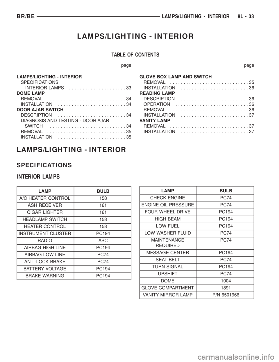
LAMPS/LIGHTING - INTERIOR
TABLE OF CONTENTS
page page
LAMPS/LIGHTING - INTERIOR
SPECIFICATIONS
INTERIOR LAMPS.....................33
DOME LAMP
REMOVAL.............................34
INSTALLATION.........................34
DOOR AJAR SWITCH
DESCRIPTION.........................34
DIAGNOSIS AND TESTING - DOOR AJAR
SWITCH............................34
REMOVAL.............................35
INSTALLATION.........................35GLOVE BOX LAMP AND SWITCH
REMOVAL.............................35
INSTALLATION.........................36
READING LAMP
DESCRIPTION.........................36
OPERATION...........................36
REMOVAL.............................36
INSTALLATION.........................37
VANITY LAMP
REMOVAL.............................37
INSTALLATION.........................37
LAMPS/LIGHTING - INTERIOR
SPECIFICATIONS
INTERIOR LAMPS
LAMP BULB
A/C HEATER CONTROL 158
ASH RECEIVER 161
CIGAR LIGHTER 161
HEADLAMP SWITCH 158
HEATER CONTROL 158
INSTRUMENT CLUSTER PC194
RADIO ASC
AIRBAG HIGH LINE PC194
AIRBAG LOW LINE PC74
ANTI-LOCK BRAKE PC74
BATTERY VOLTAGE PC194
BRAKE WARNING PC194LAMP BULB
CHECK ENGINE PC74
ENGINE OIL PRESSURE PC74
FOUR WHEEL DRIVE PC194
HIGH BEAM PC194
LOW FUEL PC194
LOW WASHER FLUID PC74
MAINTENANCE
REQUIREDPC74
MESSAGE CENTER PC194
SEAT BELT PC74
TURN SIGNAL PC194
UPSHIFT PC74
DOME 1004
GLOVE COMPARTMENT 1891
VANITY MIRROR LAMP P/N 6501966
BR/BELAMPS/LIGHTING - INTERIOR 8L - 33
Page 565 of 2255
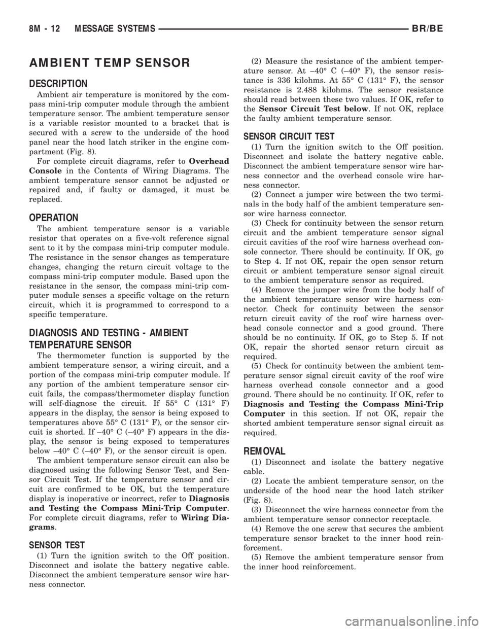
AMBIENT TEMP SENSOR
DESCRIPTION
Ambient air temperature is monitored by the com-
pass mini-trip computer module through the ambient
temperature sensor. The ambient temperature sensor
is a variable resistor mounted to a bracket that is
secured with a screw to the underside of the hood
panel near the hood latch striker in the engine com-
partment (Fig. 8).
For complete circuit diagrams, refer toOverhead
Consolein the Contents of Wiring Diagrams. The
ambient temperature sensor cannot be adjusted or
repaired and, if faulty or damaged, it must be
replaced.
OPERATION
The ambient temperature sensor is a variable
resistor that operates on a five-volt reference signal
sent to it by the compass mini-trip computer module.
The resistance in the sensor changes as temperature
changes, changing the return circuit voltage to the
compass mini-trip computer module. Based upon the
resistance in the sensor, the compass mini-trip com-
puter module senses a specific voltage on the return
circuit, which it is programmed to correspond to a
specific temperature.
DIAGNOSIS AND TESTING - AMBIENT
TEMPERATURE SENSOR
The thermometer function is supported by the
ambient temperature sensor, a wiring circuit, and a
portion of the compass mini-trip computer module. If
any portion of the ambient temperature sensor cir-
cuit fails, the compass/thermometer display function
will self-diagnose the circuit. If 55É C (131É F)
appears in the display, the sensor is being exposed to
temperatures above 55É C (131É F), or the sensor cir-
cuit is shorted. If ±40É C (±40É F) appears in the dis-
play, the sensor is being exposed to temperatures
below ±40É C (±40É F), or the sensor circuit is open.
The ambient temperature sensor circuit can also be
diagnosed using the following Sensor Test, and Sen-
sor Circuit Test. If the temperature sensor and cir-
cuit are confirmed to be OK, but the temperature
display is inoperative or incorrect, refer toDiagnosis
and Testing the Compass Mini-Trip Computer.
For complete circuit diagrams, refer toWiring Dia-
grams.
SENSOR TEST
(1) Turn the ignition switch to the Off position.
Disconnect and isolate the battery negative cable.
Disconnect the ambient temperature sensor wire har-
ness connector.(2) Measure the resistance of the ambient temper-
ature sensor. At ±40É C (±40É F), the sensor resis-
tance is 336 kilohms. At 55É C (131É F), the sensor
resistance is 2.488 kilohms. The sensor resistance
should read between these two values. If OK, refer to
theSensor Circuit Test below. If not OK, replace
the faulty ambient temperature sensor.
SENSOR CIRCUIT TEST
(1) Turn the ignition switch to the Off position.
Disconnect and isolate the battery negative cable.
Disconnect the ambient temperature sensor wire har-
ness connector and the overhead console wire har-
ness connector.
(2) Connect a jumper wire between the two termi-
nals in the body half of the ambient temperature sen-
sor wire harness connector.
(3) Check for continuity between the sensor return
circuit and the ambient temperature sensor signal
circuit cavities of the roof wire harness overhead con-
sole connector. There should be continuity. If OK, go
to Step 4. If not OK, repair the open sensor return
circuit or ambient temperature sensor signal circuit
to the ambient temperature sensor as required.
(4) Remove the jumper wire from the body half of
the ambient temperature sensor wire harness con-
nector. Check for continuity between the sensor
return circuit cavity of the roof wire harness over-
head console connector and a good ground. There
should be no continuity. If OK, go to Step 5. If not
OK, repair the shorted sensor return circuit as
required.
(5) Check for continuity between the ambient tem-
perature sensor signal circuit cavity of the roof wire
harness overhead console connector and a good
ground. There should be no continuity. If OK, refer to
Diagnosis and Testing the Compass Mini-Trip
Computerin this section. If not OK, repair the
shorted ambient temperature sensor signal circuit as
required.
REMOVAL
(1) Disconnect and isolate the battery negative
cable.
(2) Locate the ambient temperature sensor, on the
underside of the hood near the hood latch striker
(Fig. 8).
(3) Disconnect the wire harness connector from the
ambient temperature sensor connector receptacle.
(4) Remove the one screw that secures the ambient
temperature sensor bracket to the inner hood rein-
forcement.
(5) Remove the ambient temperature sensor from
the inner hood reinforcement.
8M - 12 MESSAGE SYSTEMSBR/BE