front control module DODGE RAM 2002 Service Repair Manual
[x] Cancel search | Manufacturer: DODGE, Model Year: 2002, Model line: RAM, Model: DODGE RAM 2002Pages: 2255, PDF Size: 62.07 MB
Page 225 of 2255
OPERATION
Battery voltage is supplied to the CAB when a
speed of 15 miles per hour is reached. The CAB per-
forms a system initialization procedure at this point.
Initialization consists of a static and dynamic self
check of system electrical components.
The static and dynamic checks occurs at ignition
start up. During the dynamic check, the CAB briefly
cycles the pump and solenoids to verify operation. An
audible noise may be heard during this self check.
This noise should be considered normal.
If an ABS component exhibits a fault during ini-
tialization, the CAB illuminates the amber warning
light and registers a fault code in the microprocessor
memory.
The CAB monitors wheel speed sensor inputs con-
tinuously while the vehicle is in motion. However,
the CAB will not activate any ABS components as
long as sensor inputs indicate normal braking.
During normal braking, the master cylinder, power
booster and wheel brake units all function as they
would in a vehicle without ABS. The HCU compo-
nents are not activated.
The purpose of the antilock system is to prevent
wheel lockup during periods of high wheel slip. Pre-
venting lockup helps maintain vehicle braking action
and steering control.
The antilock CAB activates the system whenever
sensor signals indicate periods of wheel slip. Periods
of wheel slip occur when brake stops involve high
pedal pressure and rate of vehicle deceleration.
The antilock system prevents lockup during a
wheel slip condition by modulating fluid apply pres-
sure to the wheel brake units.
Brake fluid apply pressure is modulated according
to wheel speed, degree of slip and rate of decelera-
tion. Sensors at each front wheel convert wheel speed
into electrical signals. These signals are transmitted
to the CAB for processing and determination of
wheel slip and deceleration rate.
The ABS system has three fluid pressure control
channels. The front brakes are controlled separately
and the rear brakes in tandem. A speed sensor input
signal indicating a wheel slip condition activates the
CAB antilock program.
There are Two solenoid valves (Isolation and Dump
valve) which are used in each antilock control chan-
nel. The valves are all located within the HCU valve
body and work in pairs to either increase, hold, or
decrease apply pressure as needed in the individual
control channels.
During an ABS stop the ISO valve actuates, Stop-
ping anymore pressure build Ðup to the calipers.
Then the Dump valve dumps off pressure until the
wheel unlocks. This will continue until the wheels
quit slipping altogether.
DIAGNOSIS AND TESTING - ANTILOCK
BRAKES
The ABS brake system performs several self-tests
every time the ignition switch is turned on and the
vehicle is driven. The CAB monitors the systems
input and output circuits to verify the system is oper-
ating correctly. If the on board diagnostic system
senses that a circuit is malfunctioning the system
will set a trouble code in its memory.
NOTE: An audible noise may be heard during the
self-test. This noise should be considered normal.
NOTE: The MDS or DRB III scan tool is used to
diagnose the ABS system. For additional informa-
tion refer to the Antilock Brake section in Group
8W. For test procedures refer to the Chassis Diag-
nostic Manual.
STANDARD PROCEDURE
STANDARD PROCEDURE - RWAL SERVICE
PRECAUTIONS
The RWAL uses an electronic control module, the
CAB. This module is designed to withstand normal
current draws associated with vehicle operation.
Care must be taken to avoid overloading the CAB
circuits.In testing for open or short circuits, do
not ground or apply voltage to any of the cir-
cuits unless instructed to do so for a diagnostic
procedure.These circuits should only be tested
using a high impedance multi-meter or the DRB
tester as described in this section. Power should
never be removed or applied to any control module
with the ignition in the ON position. Before removing
or connecting battery cables, fuses, or connectors,
always turn the ignition to the OFF position.
CAUTION: Use only factory wiring harnesses. Do
not cut or splice wiring to the brake circuits. The
addition of after-market electrical equipment (car
phone, radar detector, citizen band radio, trailer
lighting, trailer brakes, ect.) on a vehicle equipped
with antilock brakes may affect the function of the
antilock brake system.
STANDARD PROCEDURE - BLEEDING ABS
BRAKE SYSTEM
ABS system bleeding requires conventional bleed-
ing methods plus use of the DRB scan tool. The pro-
cedure involves performing a base brake bleeding,
followed by use of the scan tool to cycle and bleed the
5 - 36 BRAKES - ABSBR/BE
BRAKES - ABS (Continued)
Page 290 of 2255
INSTALLATION
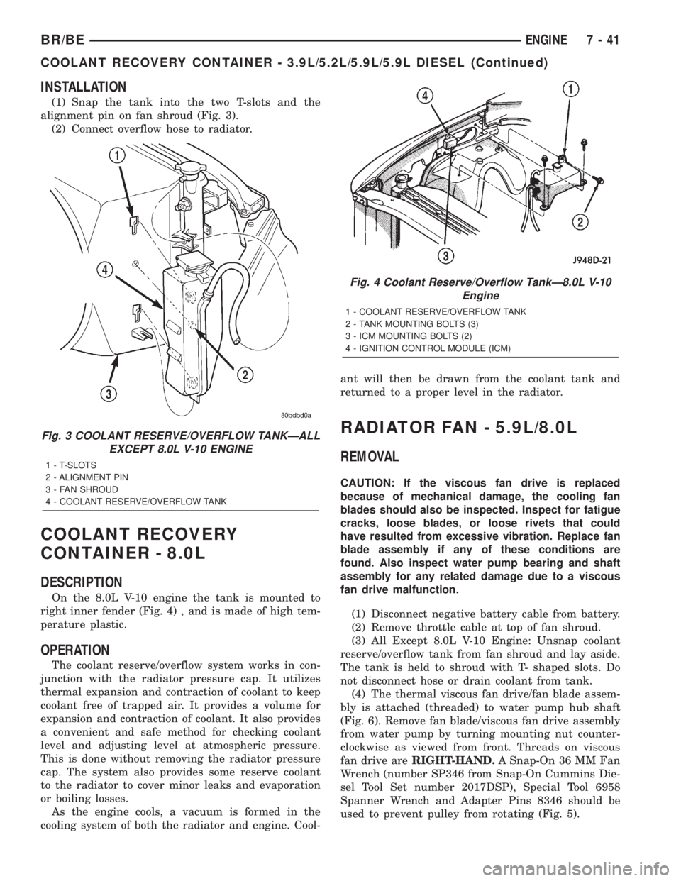
(1) Snap the tank into the two T-slots and the
alignment pin on fan shroud (Fig. 3).
(2) Connect overflow hose to radiator.
COOLANT RECOVERY
CONTAINER - 8.0L
DESCRIPTION
On the 8.0L V-10 engine the tank is mounted to
right inner fender (Fig. 4) , and is made of high tem-
perature plastic.
OPERATION
The coolant reserve/overflow system works in con-
junction with the radiator pressure cap. It utilizes
thermal expansion and contraction of coolant to keep
coolant free of trapped air. It provides a volume for
expansion and contraction of coolant. It also provides
a convenient and safe method for checking coolant
level and adjusting level at atmospheric pressure.
This is done without removing the radiator pressure
cap. The system also provides some reserve coolant
to the radiator to cover minor leaks and evaporation
or boiling losses.
As the engine cools, a vacuum is formed in the
cooling system of both the radiator and engine. Cool-ant will then be drawn from the coolant tank and
returned to a proper level in the radiator.
RADIATOR FAN - 5.9L/8.0L
REMOVAL
CAUTION: If the viscous fan drive is replaced
because of mechanical damage, the cooling fan
blades should also be inspected. Inspect for fatigue
cracks, loose blades, or loose rivets that could
have resulted from excessive vibration. Replace fan
blade assembly if any of these conditions are
found. Also inspect water pump bearing and shaft
assembly for any related damage due to a viscous
fan drive malfunction.
(1) Disconnect negative battery cable from battery.
(2) Remove throttle cable at top of fan shroud.
(3) All Except 8.0L V-10 Engine: Unsnap coolant
reserve/overflow tank from fan shroud and lay aside.
The tank is held to shroud with T- shaped slots. Do
not disconnect hose or drain coolant from tank.
(4) The thermal viscous fan drive/fan blade assem-
bly is attached (threaded) to water pump hub shaft
(Fig. 6). Remove fan blade/viscous fan drive assembly
from water pump by turning mounting nut counter-
clockwise as viewed from front. Threads on viscous
fan drive areRIGHT-HAND.A Snap-On 36 MM Fan
Wrench (number SP346 from Snap-On Cummins Die-
sel Tool Set number 2017DSP), Special Tool 6958
Spanner Wrench and Adapter Pins 8346 should be
used to prevent pulley from rotating (Fig. 5).
Fig. 3 COOLANT RESERVE/OVERFLOW TANKÐALL
EXCEPT 8.0L V-10 ENGINE
1 - T-SLOTS
2 - ALIGNMENT PIN
3 - FAN SHROUD
4 - COOLANT RESERVE/OVERFLOW TANK
Fig. 4 Coolant Reserve/Overflow TankÐ8.0L V-10
Engine
1 - COOLANT RESERVE/OVERFLOW TANK
2 - TANK MOUNTING BOLTS (3)
3 - ICM MOUNTING BOLTS (2)
4 - IGNITION CONTROL MODULE (ICM)
BR/BEENGINE 7 - 41
COOLANT RECOVERY CONTAINER - 3.9L/5.2L/5.9L/5.9L DIESEL (Continued)
Page 297 of 2255
ENGINE COOLANT
THERMOSTAT - 5.9L
DESCRIPTION
CAUTION: Do not operate an engine without a ther-
mostat, except for servicing or testing.
The thermostat on the 5.9L gas powered engine is
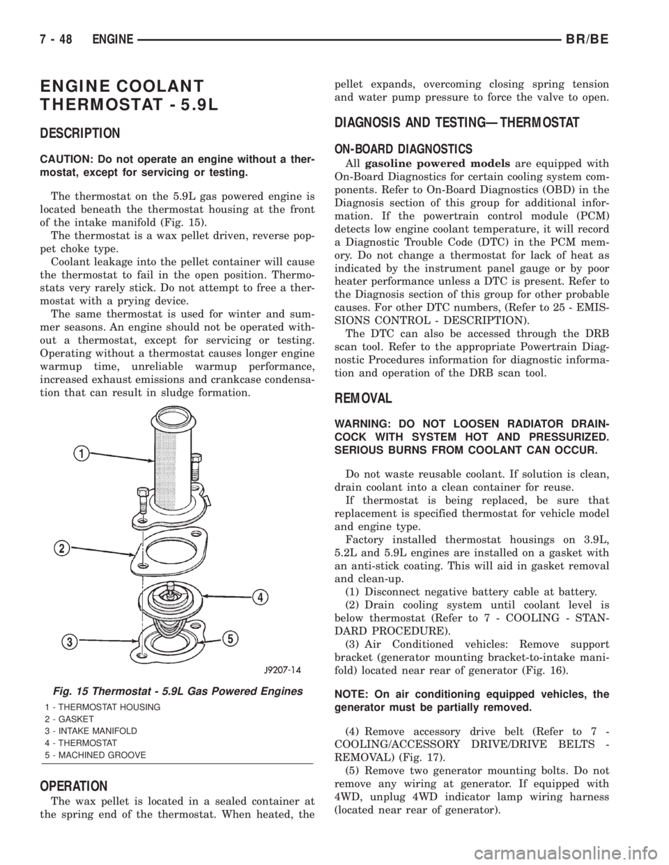
located beneath the thermostat housing at the front
of the intake manifold (Fig. 15).
The thermostat is a wax pellet driven, reverse pop-
pet choke type.
Coolant leakage into the pellet container will cause
the thermostat to fail in the open position. Thermo-
stats very rarely stick. Do not attempt to free a ther-
mostat with a prying device.
The same thermostat is used for winter and sum-
mer seasons. An engine should not be operated with-
out a thermostat, except for servicing or testing.
Operating without a thermostat causes longer engine
warmup time, unreliable warmup performance,
increased exhaust emissions and crankcase condensa-
tion that can result in sludge formation.
OPERATION
The wax pellet is located in a sealed container at
the spring end of the thermostat. When heated, thepellet expands, overcoming closing spring tension
and water pump pressure to force the valve to open.
DIAGNOSIS AND TESTINGÐTHERMOSTAT
ON-BOARD DIAGNOSTICS
Allgasoline powered modelsare equipped with
On-Board Diagnostics for certain cooling system com-
ponents. Refer to On-Board Diagnostics (OBD) in the
Diagnosis section of this group for additional infor-
mation. If the powertrain control module (PCM)
detects low engine coolant temperature, it will record
a Diagnostic Trouble Code (DTC) in the PCM mem-
ory. Do not change a thermostat for lack of heat as
indicated by the instrument panel gauge or by poor
heater performance unless a DTC is present. Refer to
the Diagnosis section of this group for other probable
causes. For other DTC numbers, (Refer to 25 - EMIS-
SIONS CONTROL - DESCRIPTION).
The DTC can also be accessed through the DRB
scan tool. Refer to the appropriate Powertrain Diag-
nostic Procedures information for diagnostic informa-
tion and operation of the DRB scan tool.
REMOVAL
WARNING: DO NOT LOOSEN RADIATOR DRAIN-
COCK WITH SYSTEM HOT AND PRESSURIZED.
SERIOUS BURNS FROM COOLANT CAN OCCUR.
Do not waste reusable coolant. If solution is clean,
drain coolant into a clean container for reuse.
If thermostat is being replaced, be sure that
replacement is specified thermostat for vehicle model
and engine type.
Factory installed thermostat housings on 3.9L,
5.2L and 5.9L engines are installed on a gasket with
an anti-stick coating. This will aid in gasket removal
and clean-up.
(1) Disconnect negative battery cable at battery.
(2) Drain cooling system until coolant level is
below thermostat (Refer to 7 - COOLING - STAN-
DARD PROCEDURE).
(3) Air Conditioned vehicles: Remove support
bracket (generator mounting bracket-to-intake mani-
fold) located near rear of generator (Fig. 16).
NOTE: On air conditioning equipped vehicles, the
generator must be partially removed.
(4) Remove accessory drive belt (Refer to 7 -
COOLING/ACCESSORY DRIVE/DRIVE BELTS -
REMOVAL) (Fig. 17).
(5) Remove two generator mounting bolts. Do not
remove any wiring at generator. If equipped with
4WD, unplug 4WD indicator lamp wiring harness
(located near rear of generator).
Fig. 15 Thermostat - 5.9L Gas Powered Engines
1 - THERMOSTAT HOUSING
2 - GASKET
3 - INTAKE MANIFOLD
4 - THERMOSTAT
5 - MACHINED GROOVE
7 - 48 ENGINEBR/BE
Page 300 of 2255
ENGINE COOLANT
THERMOSTAT - 8.0L
DESCRIPTION
CAUTION: Do not operate an engine without a ther-
mostat, except for servicing or testing.
The thermostat on all gas powered engines is
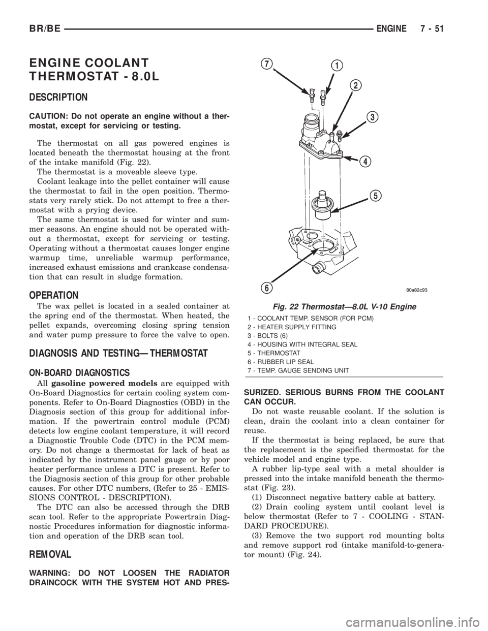
located beneath the thermostat housing at the front
of the intake manifold (Fig. 22).
The thermostat is a moveable sleeve type.
Coolant leakage into the pellet container will cause
the thermostat to fail in the open position. Thermo-
stats very rarely stick. Do not attempt to free a ther-
mostat with a prying device.
The same thermostat is used for winter and sum-
mer seasons. An engine should not be operated with-
out a thermostat, except for servicing or testing.
Operating without a thermostat causes longer engine
warmup time, unreliable warmup performance,
increased exhaust emissions and crankcase condensa-
tion that can result in sludge formation.
OPERATION
The wax pellet is located in a sealed container at
the spring end of the thermostat. When heated, the
pellet expands, overcoming closing spring tension
and water pump pressure to force the valve to open.
DIAGNOSIS AND TESTINGÐTHERMOSTAT
ON-BOARD DIAGNOSTICS
Allgasoline powered modelsare equipped with
On-Board Diagnostics for certain cooling system com-
ponents. Refer to On-Board Diagnostics (OBD) in the
Diagnosis section of this group for additional infor-
mation. If the powertrain control module (PCM)
detects low engine coolant temperature, it will record
a Diagnostic Trouble Code (DTC) in the PCM mem-
ory. Do not change a thermostat for lack of heat as
indicated by the instrument panel gauge or by poor
heater performance unless a DTC is present. Refer to
the Diagnosis section of this group for other probable
causes. For other DTC numbers, (Refer to 25 - EMIS-
SIONS CONTROL - DESCRIPTION).
The DTC can also be accessed through the DRB
scan tool. Refer to the appropriate Powertrain Diag-
nostic Procedures information for diagnostic informa-
tion and operation of the DRB scan tool.
REMOVAL
WARNING: DO NOT LOOSEN THE RADIATOR
DRAINCOCK WITH THE SYSTEM HOT AND PRES-SURIZED. SERIOUS BURNS FROM THE COOLANT
CAN OCCUR.
Do not waste reusable coolant. If the solution is
clean, drain the coolant into a clean container for
reuse.
If the thermostat is being replaced, be sure that
the replacement is the specified thermostat for the
vehicle model and engine type.
A rubber lip-type seal with a metal shoulder is
pressed into the intake manifold beneath the thermo-
stat (Fig. 23).
(1) Disconnect negative battery cable at battery.
(2) Drain cooling system until coolant level is
below thermostat (Refer to 7 - COOLING - STAN-
DARD PROCEDURE).
(3) Remove the two support rod mounting bolts
and remove support rod (intake manifold-to-genera-
tor mount) (Fig. 24).
Fig. 22 ThermostatÐ8.0L V-10 Engine
1 - COOLANT TEMP. SENSOR (FOR PCM)
2 - HEATER SUPPLY FITTING
3 - BOLTS (6)
4 - HOUSING WITH INTEGRAL SEAL
5 - THERMOSTAT
6 - RUBBER LIP SEAL
7 - TEMP. GAUGE SENDING UNIT
BR/BEENGINE 7 - 51
Page 338 of 2255
AUDIO
TABLE OF CONTENTS
page page
AUDIO
DESCRIPTION..........................1
OPERATION............................2
DIAGNOSIS AND TESTING - AUDIO..........2
SPECIAL TOOLS
AUDIO SYSTEMS......................4
ANTENNA BODY & CABLE
DESCRIPTION..........................4
OPERATION............................4
DIAGNOSIS AND TESTING - ANTENNA.......5
REMOVAL.............................6
INSTALLATION..........................6
RADIO CHOKE RELAY
DESCRIPTION..........................7
OPERATION............................8
DIAGNOSIS AND TESTING - RADIO CHOKE
RELAY...............................8
REMOVAL.............................8
INSTALLATION..........................9
INSTRUMENT PANEL ANTENNA CABLE
REMOVAL.............................9
INSTALLATION..........................9
RADIO
DESCRIPTION.........................10
OPERATION...........................10
DIAGNOSIS AND TESTING - RADIO.........10
REMOVAL.............................11
INSTALLATION.........................11
RADIO NOISE SUPPRESSION COMPONENTS
DESCRIPTION.........................12
DIAGNOSIS AND TESTING - RADIO NOISE
SUPPRESSION COMPONENTS...........12ENGINE-TO-BODY GROUND STRAP
REMOVAL.............................12
INSTALLATION.........................13
CAB-TO- BED GROUND STRAP
REMOVAL.............................13
INSTALLATION.........................14
HEATER CORE GROUND STRAP
REMOVAL.............................14
INSTALLATION.........................14
REMOTE SWITCHES
DESCRIPTION.........................14
OPERATION...........................15
DIAGNOSIS AND TESTING - REMOTE
SWITCHES..........................15
REMOVAL.............................16
INSTALLATION.........................16
SPEAKER
DESCRIPTION.........................17
OPERATION...........................17
DIAGNOSIS AND TESTING - SPEAKER......17
A-PILLAR TWEETER SPEAKER
REMOVAL.............................18
INSTALLATION.........................19
FRONT DOOR SPEAKER
REMOVAL.............................19
INSTALLATION.........................19
REAR CAB SIDE PANEL SPEAKER
REMOVAL.............................20
INSTALLATION.........................20
REAR DOOR SPEAKER
REMOVAL.............................20
INSTALLATION.........................21
AUDIO
DESCRIPTION
An audio system is standard factory-installed
equipment on this model, unless the vehicle is
ordered with an available radio delete option. The
standard equipment audio system includes an
AM/FM/cassette (RAS sales code) receiver, and
speakers in four locations. Several combinations of
radio receivers and speaker systems are offered as
optional equipment on this model. The audio system
uses an ignition switched source of battery current so
that the system will only operate when the ignition
switch is in the On or Accessory positions. The audio
system includes the following components:²Antenna
²Clockspring (with remote radio switches only)
²Filter, choke and speaker relay (with premium
speaker system only)
²High-line or premium Central Timer Module
(CTM) (with remote radio switches)
²Radio noise suppression components
²Radio receiver
²Remote radio switches (optional with RAZ radio
receiver only)
²Speakers
Refer to Electrical, Restraints for more information
on the clockspring. Refer to Electrical, Body Control/
Central Control Module for more information on the
Central Timer Module. Refer to the appropriate wir-
ing information. The wiring information includes wir-
BR/BEAUDIO 8A - 1
Page 354 of 2255
(5) Install the driver side airbag module onto the
steering wheel. Refer to Electrical, Restraints for the
procedures.
(6) Reconnect the battery negative cable.
SPEAKER
DESCRIPTION
STANDARD
The standard equipment speaker system includes
speakers in four locations. One full-range 15.2 by
22.9 centimeter (6.0 by 9.0 inch) speaker is located in
each front door. There is also one full-range 13.3 cen-
timeter (5.25 inch) diameter speaker located in each
rear cab side panel for the standard cab and the club
cab models, or in each rear door of the quad cab mod-
els.
PREMIUM
The optional premium speaker system features
Infinity model speakers in six locations. Each of the
standard front door speakers are replaced with Infin-
ity model speakers that include integral dual 30 watt
amplifiers. Each of the standard rear speakers is also
replaced by an Infinity model speaker. The premium
speaker system also includes an additional Infinity
tweeter mounted in the A-pillar garnish molding. The
total available power of the premium speaker system
is about 120 watts.
OPERATION
STANDARD
Each of the four full-range speakers used in the
standard speaker system is driven by the amplifier
that is integral to the factory-installed radio receiver.
For complete circuit diagrams, refer to the appropri-
ate wiring information. The wiring information
includes wiring diagrams, proper wire and connector
repair procedures, details of wire harness routing
and retention, connector pin-out information and
location views for the various wire harness connec-
tors, splices and grounds.
PREMIUM
The Infinity speakers used in the premium speaker
system are driven by dual amplifiers that are inte-
gral to each of the front door speakers. One of these
dual amplifiers drives the front door speaker and the
A-pillar mounted tweeter for that side of the vehicle,
while the other amplifier drives the rear speaker for
that side of the vehicle. For complete circuit dia-
grams, to refer to the appropriate wiring information.
The wiring information includes wiring diagrams,proper wire and connector repair procedures, details
of wire harness routing and retention, connector pin-
out information and location views for the various
wire harness connectors, splices and grounds.
DIAGNOSIS AND TESTING - SPEAKER
For complete circuit diagrams, refer to the appro-
priate wiring information. The wiring information
includes wiring diagrams, proper wire and connector
repair procedures, details of wire harness routing
and retention, connector pin-out information and
location views for the various wire harness connec-
tors, splices and grounds.
WARNING: ON VEHICLES EQUIPPED WITH AIR-
BAGS, REFER TO ELECTRICAL, RESTRAINTS
BEFORE ATTEMPTING ANY STEERING WHEEL,
STEERING COLUMN, OR INSTRUMENT PANEL
COMPONENT DIAGNOSIS OR SERVICE. FAILURE
TO TAKE THE PROPER PRECAUTIONS COULD
RESULT IN ACCIDENTAL AIRBAG DEPLOYMENT
AND POSSIBLE PERSONAL INJURY.
CAUTION: The speaker output of the radio receiver
is a ªfloating groundº system. Do not allow any
speaker lead to short to ground, as damage to the
radio receiver may result.
(1) Turn the ignition switch to the On position.
Turn the radio receiver on. Adjust the balance and
fader controls to check the performance of each indi-
vidual speaker. Note the speaker locations that are
not performing correctly. If only an Infinity A-pillar
or an Infinity rear speaker is inoperative, go to Step
8. If any other speaker is inoperative, go to Step 2.
NOTE: If the vehicle is equipped with the Infinity
premium speaker package and all of the speakers
are inoperative, refer to Filter, Choke, and Speaker
Relay in the Diagnosis and Testing section of this
group.
(2) Turn the radio receiver off. Turn the ignition
switch to the Off position. Disconnect and isolate the
battery negative cable. Remove the radio receiver
from the instrument panel. Check both the feed (+)
circuit and return (±) circuit cavities for the inopera-
tive speaker location(s) in the radio receiver wire
harness connectors for continuity to ground. In each
case, there should be no continuity. If OK, go to Step
3. If not OK, repair the shorted speaker feed (+)
and/or return (±) circuit(s) to the speaker as required.
(3) If the inoperative speaker is an Infinity-ampli-
fied speaker, go to Step 5. If the vehicle is equipped
with the standard speaker system, check the resis-
tance between the speaker feed (+) circuit and return
BR/BEAUDIO 8A - 17
REMOTE SWITCHES (Continued)
Page 385 of 2255
To avoid possible voltage spike damage to the
PCM, ignition key must be off, and negative battery
cable must be disconnected before unplugging PCM
connectors.
(1) Disconnect negative battery cable(s) at bat-
tery(s).
(2) Remove cover over electrical connectors. Cover
snaps onto PCM.
(3) Carefully unplug the three 32±way connectors
from PCM.
(4) Remove three PCM mounting bolts and remove
PCM from vehicle.
INSTALLATION
USE THE DRB SCAN TOOL TO REPROGRAM
THE NEW POWERTRAIN CONTROL MODULE
(PCM) WITH THE VEHICLES ORIGINAL IDEN-
TIFICATION NUMBER (VIN) AND THE VEHI-
CLES ORIGINAL MILEAGE. IF THIS STEP IS
NOT DONE, A DIAGNOSTIC TROUBLE CODE
(DTC) MAY BE SET.
(1) Install PCM and mounting bolts to vehicle.
(2) Tighten bolts to 4 N´m (35 in. lbs.).
(3) Check pin connectors in the PCM and the three
32±way connectors for corrosion or damage. Repair
as necessary.
(4) Install three 32±way connectors.
(5) Install cover over electrical connectors. Cover
snaps onto PCM.
(6) Install battery cable(s).
(7) Use the DRB scan tool to reprogram new PCM
with vehicles original Identification Number (VIN)
and original vehicle mileage. If this step is not done,
a Diagnostic Trouble Code (DTC) may be set.
HEATED SEAT MODULE
DESCRIPTION
The heated seat module is also known as the Seat
Heat Interface Module. The heated seat module (Fig.
19) is located under the front seat center cushion,
where it is secured to a mounting bracket that also
serves as the support for the slide-out rear seat cup
holder unit. The mounting tabs that are molded into
the plastic housing of the heated seat module are
inserted through holes in the mounting bracket and
then secured by push on retainers. The heated seat
module has a single connector receptacle that allows
the module to be connected to all of the required
inputs and outputs through the seat wire harness.
The heated seat module is an electronic micropro-
cessor controlled device designed and programmed to
use inputs from the heated seat relay, the two heated
seat switches and the two heated seat sensors to
operate and control the heated seat elements in both
front seats and the two heated seat indicator lamp
Light-Emitting Diodes (LEDs) in each heated seat
switch. The heated seat module is also programmed
to perform self-diagnosis of certain heated seat sys-
tem functions and provide feedback of that diagnosis
through the heated seat switch indicator lamps.
The heated seat module cannot be repaired. If the
heated seat module is damaged or faulty, the entire
module must be replaced.
OPERATION
The heated seat module operates on fused battery
current received from the heated seat relay. The
module is grounded at all times through a ground
screw located below the left rear speaker in the cab
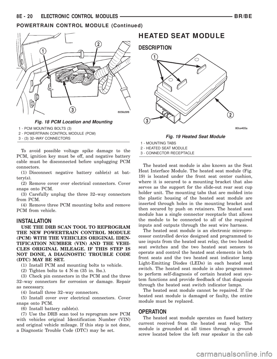
Fig. 18 PCM Location and Mounting
1 - PCM MOUNTING BOLTS (3)
2 - POWERTRAIN CONTROL MODULE (PCM)
3 - (3) 32±WAY CONNECTORS
Fig. 19 Heated Seat Module
1 - MOUNTING TABS
2 - HEATED SEAT MODULE
3 - CONNECTOR RECEPTACLE
8E - 20 ELECTRONIC CONTROL MODULESBR/BE
POWERTRAIN CONTROL MODULE (Continued)
Page 386 of 2255
of the vehicle. Inputs to the module include a resistor
multiplexed heated seat switch request circuit for
each of the two heated seat switches and the heated
seat sensor inputs from the seat cushions of each
front seat. In response to those inputs the heated
seat module controls battery current feeds to the
heated seat elements and sensors, and controls the
ground for the heated seat switch indicator lamps.
NOTE: The vehicle's engine must be running in
order for the heated seat system to function. This
eliminates the possibility of draining the vehicles
battery voltage while operating the heated seat sys-
tem.
When a heated seat switch (Driver or Passenger) is
depressed a signal is received by the heated seat
module, the module energizes the proper indicator
LED (Low or High) in the switch by grounding the
indicator lamp circuit to indicate that the heated seat
system is operating. At the same time, the heated
seat module energizes the selected heated seat sensor
circuit and the sensor provides the module with an
input indicating the surface temperature of the
selected seat cushion.
The Low heat set point is about 36É C (96.8É F),
and the High heat set point is about 42É C (107.6É F).
If the seat cushion surface temperature input is
below the temperature set point for the selected tem-
perature setting, the heated seat module energizes
an N-channel Field Effect Transistor (N-FET) within
the module which energizes the heated seat elements
in the selected seat cushion and back. When the sen-
sor input to the module indicates the correct temper-
ature set point has been achieved, the module
de-energizes the N-FET which de-energizes the
heated seat elements. The heated seat module will
continue to cycle the N-FET as needed to maintain
the selected temperature set point.
If the heated seat module detects a heated seat
sensor value input that is out of range or a shorted
or open heated seat element circuit, it will notify the
vehicle operator or the repair technician of this con-
dition by flashing the High and/or Low indicator
lamps in the affected heated seat switch. Refer to
Diagnosis and Testing Heated Seat Systemin
Heated Systems for flashing LED diagnosis and test-
ing procedures. Refer toDiagnosis and Testing
Heated Seat Modulein this section for heated seat
module diagnosis and testing procedures. Also refer
to the Body Diagnostic Manual for additional diagno-
sis and testing procedures.DIAGNOSIS AND TESTING - HEATED SEAT
MODULE
If a heated seat fails to heat and one or both of the
indicator lamps on a heated seat switch flash, refer
toHeated Seat System Diagnosis and Testingin
Heated Systems for flashing LED failure identifica-
tion. Refer toWiring Diagramsin for complete
heated seat system wiring diagrams.
(1) Remove the heated seat module from its
mounting location (Refer to 8 - ELECTRICAL/ELEC-
TRONIC CONTROL MODULES/MEMORY HEATED
SEAT/MIRROR MODULE - REMOVAL).
NOTE: IN ORDER TO PERFORM THE FOLLOWING
TESTS IT WILL BE NECESSARY TO REMOVE THE
HEATED SEAT RELAY AND INSTALL A JUMPER
WIRE IN TERMINALS 87 AND 30, BYPASSING THE
HEATED SEAT RELAY.
NOTE: ANY RESISTANCE VALUES (OHMSV) GIVEN
IN THE FOLLOWING TEXT ARE SUPPLIED USING
THE AUTOMATIC RANGE GENERATED BY A
FLUKETAUTOMOTIVE METER. IF ANOTHER TYPE
OF MEASURING DEVICE IS USED THE VALUES
GENERATED MAY NOT BE THE SAME AS THE
RESULTS SHOWN HERE, OR MAY HAVE TO BE
CONVERTED TO THE RANGE USED HERE.
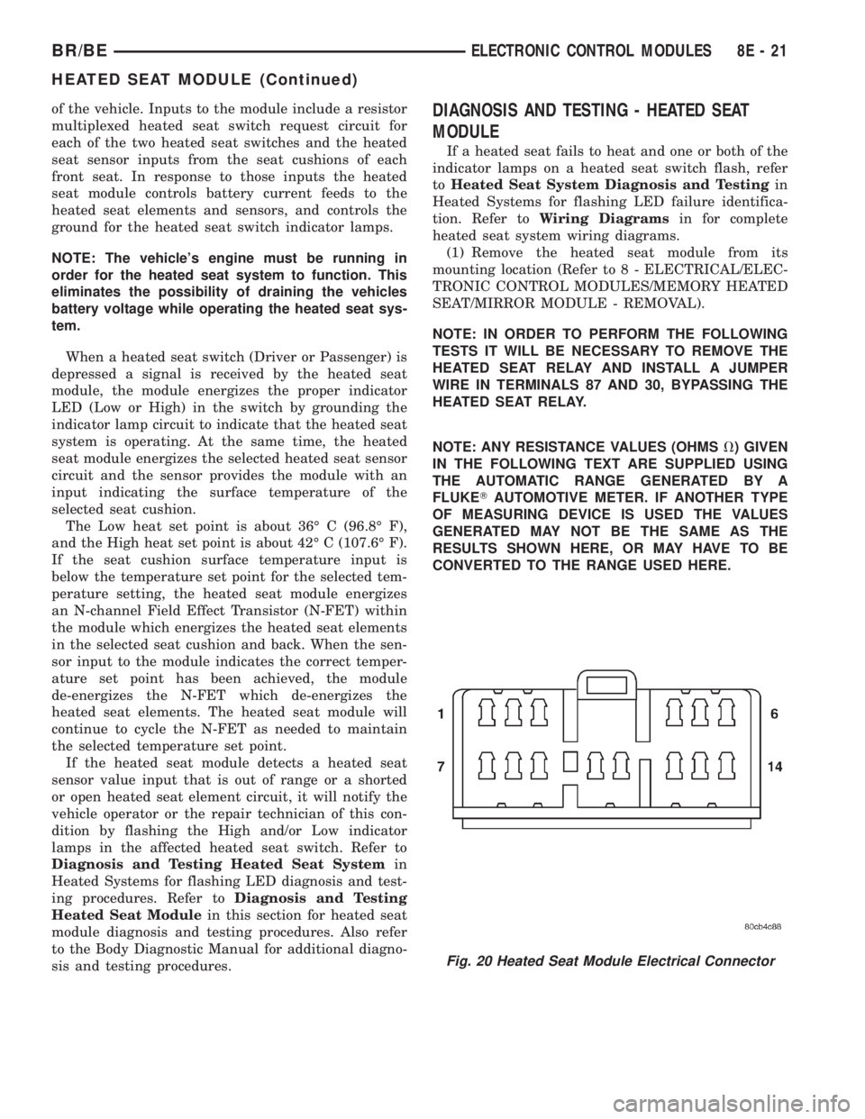
Fig. 20 Heated Seat Module Electrical Connector
BR/BEELECTRONIC CONTROL MODULES 8E - 21
HEATED SEAT MODULE (Continued)
Page 388 of 2255
(5) Back-probe the heated seat module wire har-
ness connector (Fig. 20) , do not disconnect. Check
cavity #2 for approx. 5v, 5 voltage should be present,
If OK go to Step 6. If NOT OK replace the heated
seat control module.
(6) Back-probe the heated seat module wire har-
ness connector, do not disconnect. Check cavity #8 for
a range in voltage from 1.72v (warm seat) ± 3.0v
(cold seat). It should be within this range, If OK
replace the heated seat control module. If NOT OK,
test the Heated Seat Sensor. If NOT OK, replace the
left heated seat element and sensor assembly. If the
heated seat sensor tests OK, check for continuity
between the left heated seat cushion connector and
control module connector on the 5v supply circuit, If
NOT OK, repair the open or shorted 5v supply circuit
as required. If OK check for continuity between the
left heated seat cushion connector and control mod-
ule connector on the temperature sensor input cir-
cuit. If NOT OK, repair the open or shorted
temperature sensor input circuit as required. If OK
replace the heated seat control module.
BOTH SEATS INOPERATIVE
If both seats (driver and passenger) fail to heat
and the indicator lamps on the heated seat switches
for both seats fail to operate, test the heated seat
relay and/or fuses. Refer toRelay Diagnosis and
Testingin the Power Distribution section for heated
seat relay diagnosis and testing procedures. If the
heated seat relay checks OK, go to Step 1.
(1) Back-probe the heated seat module wire har-
ness connector (Fig. 20) , do not disconnect. Check for
continuity between the ground circuit cavity #13 of
the heated seat module connector and a good ground.
If OK go to Step 2. If NOT OK, repair the open or
shorted ground circuit as required.
(2) Back-probe the heated seat module wire har-
ness connector (Fig. 20) , do not disconnect. Check
cavity #4 and #6 for battery voltage, voltage should
be present, If OK go to Step 3. If NOT OK repair the
open or shorted fused B(+) circuit as required.
(3) Back-probe the heated seat module wire har-
ness connector, do not disconnect. Check cavity #2 for
approx. 5v, voltage should be present, replace the
heated seat control module with a known good mod-
ule and verify system operation.
REMOVAL
(1) Working under the center front seat console,
cut the tiestrap and remove the two push-on retain-
ers that secure the mounting tabs of the heated seat
module to the of the mounting bracket.
(2) Position the driver seat to the full forward and
inclined position and working under the center of the
front seat, from behind the seat, disconnect the seat
wire harness connector from the connector receptacle
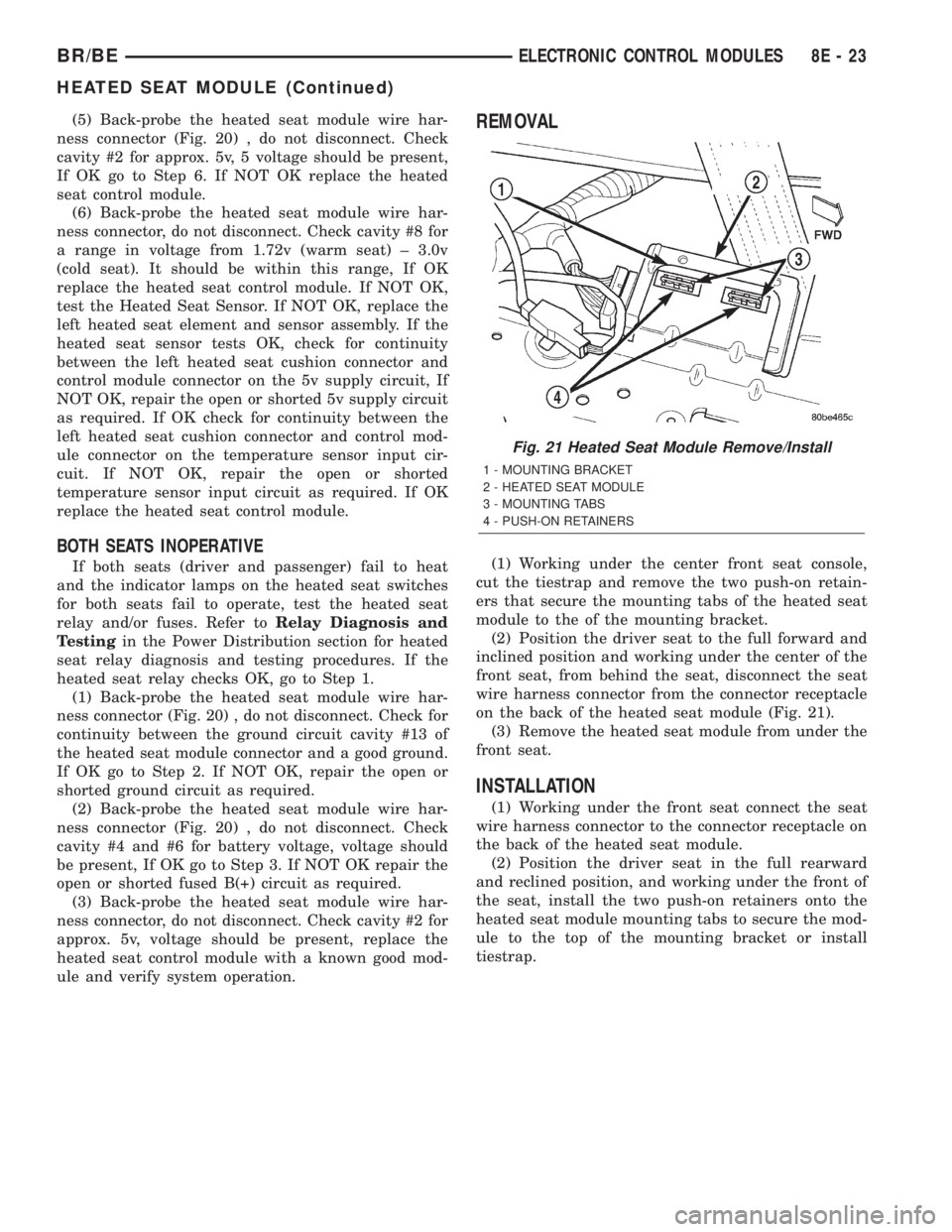
on the back of the heated seat module (Fig. 21).
(3) Remove the heated seat module from under the
front seat.
INSTALLATION
(1) Working under the front seat connect the seat
wire harness connector to the connector receptacle on
the back of the heated seat module.
(2) Position the driver seat in the full rearward
and reclined position, and working under the front of
the seat, install the two push-on retainers onto the
heated seat module mounting tabs to secure the mod-
ule to the top of the mounting bracket or install
tiestrap.
Fig. 21 Heated Seat Module Remove/Install
1 - MOUNTING BRACKET
2 - HEATED SEAT MODULE
3 - MOUNTING TABS
4 - PUSH-ON RETAINERS
BR/BEELECTRONIC CONTROL MODULES 8E - 23
HEATED SEAT MODULE (Continued)
Page 436 of 2255
HEATED SEAT SYSTEM
TABLE OF CONTENTS
page page
HEATED SEAT SYSTEM
DESCRIPTION..........................5
OPERATION............................6
DIAGNOSIS AND TESTING - HEATED SEAT
SYSTEM.............................6
DRIVER SEAT HEATER SWITCH
DESCRIPTION..........................7
OPERATION............................8
DIAGNOSIS AND TESTING - HEATED SEAT
SWITCH.............................8
REMOVAL.............................9
INSTALLATION.........................10
HEATED SEAT ELEMENT
DESCRIPTION.........................10
OPERATION...........................11
DIAGNOSIS AND TESTING - HEATED SEAT
ELEMENT AND SENSOR................11REMOVAL.............................13
INSTALLATION.........................13
HEATED SEAT RELAY
DESCRIPTION.........................14
OPERATION...........................15
DIAGNOSIS AND TESTING - HEATED SEAT
RELAY..............................15
REMOVAL.............................16
INSTALLATION.........................16
PASSENGER SEAT HEATER SWITCH
DESCRIPTION.........................16
OPERATION...........................17
DIAGNOSIS AND TESTING - HEATED SEAT
SWITCH............................17
REMOVAL.............................18
INSTALLATION.........................19
HEATED SEAT SYSTEM
DESCRIPTION
Individually controlled electrically heated front
seats are available factory-installed optional equip-
ment on the Ram quad cab models that are also
equipped with the optional SLT Plus (leather) trim
package. Vehicles with this option can be visually
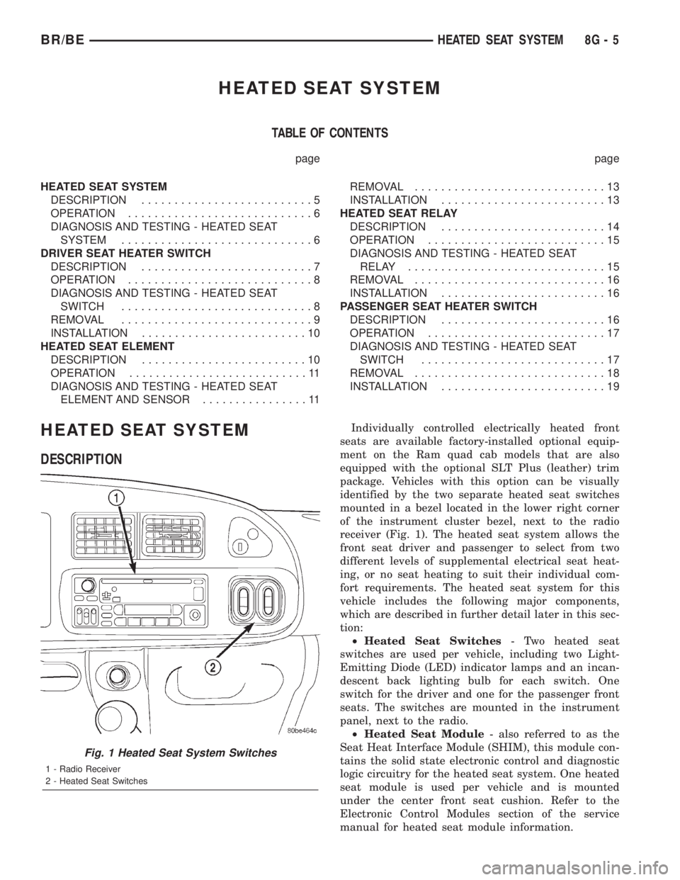
identified by the two separate heated seat switches
mounted in a bezel located in the lower right corner
of the instrument cluster bezel, next to the radio
receiver (Fig. 1). The heated seat system allows the
front seat driver and passenger to select from two
different levels of supplemental electrical seat heat-
ing, or no seat heating to suit their individual com-
fort requirements. The heated seat system for this
vehicle includes the following major components,
which are described in further detail later in this sec-
tion:
²Heated Seat Switches- Two heated seat
switches are used per vehicle, including two Light-
Emitting Diode (LED) indicator lamps and an incan-
descent back lighting bulb for each switch. One
switch for the driver and one for the passenger front
seats. The switches are mounted in the instrument
panel, next to the radio.
²Heated Seat Module- also referred to as the
Seat Heat Interface Module (SHIM), this module con-
tains the solid state electronic control and diagnostic
logic circuitry for the heated seat system. One heated
seat module is used per vehicle and is mounted
under the center front seat cushion. Refer to the
Electronic Control Modules section of the service
manual for heated seat module information.
Fig. 1 Heated Seat System Switches
1 - Radio Receiver
2 - Heated Seat Switches
BR/BEHEATED SEAT SYSTEM 8G - 5