window switch DODGE RAM 2002 Service Repair Manual
[x] Cancel search | Manufacturer: DODGE, Model Year: 2002, Model line: RAM, Model: DODGE RAM 2002Pages: 2255, PDF Size: 62.07 MB
Page 432 of 2255
HEATED SYSTEMS
TABLE OF CONTENTS
page page
HEATED MIRRORS......................... 1 HEATED SEATSYSTEM..................... 5
HEATED MIRRORS
TABLE OF CONTENTS
page page
HEATED MIRRORS
DESCRIPTION - HEATED MIRROR SYSTEM . . . 1
OPERATION - HEATED MIRROR SYSTEM.....2
DIAGNOSIS AND TESTING - HEATED
MIRROR SYSTEM......................2
MIRROR SWITCH
DESCRIPTION..........................2
OPERATION............................3DIAGNOSIS AND TESTING - HEATED
MIRROR SWITCH......................3
HEATED MIRROR GRID
DESCRIPTION..........................4
OPERATION............................4
DIAGNOSIS AND TESTING - HEATED
MIRROR GRID.........................4
HEATED MIRRORS
DESCRIPTION - HEATED MIRROR SYSTEM
Electrically heated outside rear view mirrors are
an additional factory-installed option on models that
are equipped with factory-installed dual power mir-
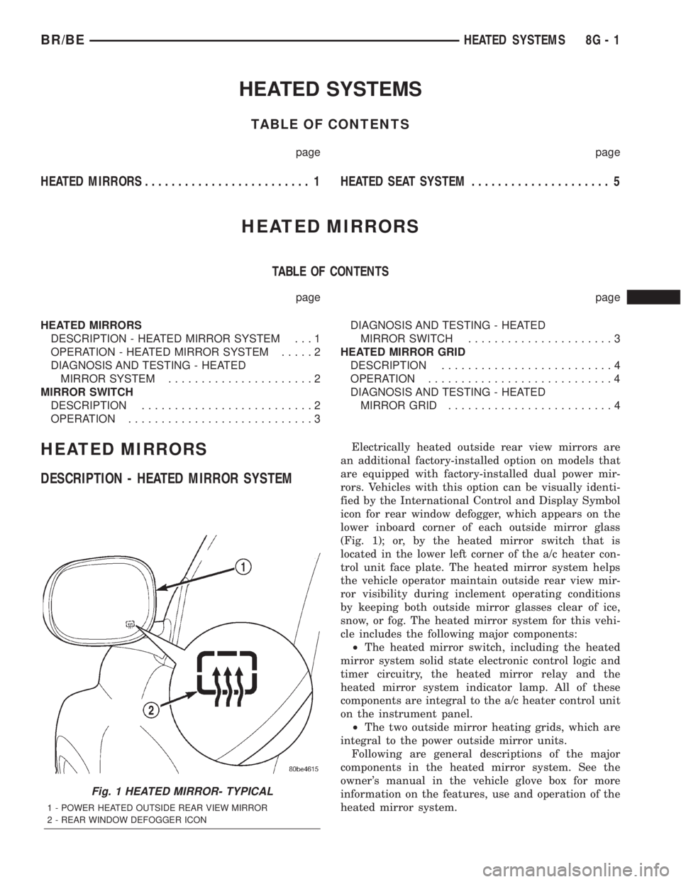
rors. Vehicles with this option can be visually identi-
fied by the International Control and Display Symbol
icon for rear window defogger, which appears on the
lower inboard corner of each outside mirror glass
(Fig. 1); or, by the heated mirror switch that is
located in the lower left corner of the a/c heater con-
trol unit face plate. The heated mirror system helps
the vehicle operator maintain outside rear view mir-
ror visibility during inclement operating conditions
by keeping both outside mirror glasses clear of ice,
snow, or fog. The heated mirror system for this vehi-
cle includes the following major components:
²The heated mirror switch, including the heated
mirror system solid state electronic control logic and
timer circuitry, the heated mirror relay and the
heated mirror system indicator lamp. All of these
components are integral to the a/c heater control unit
on the instrument panel.
²The two outside mirror heating grids, which are
integral to the power outside mirror units.
Following are general descriptions of the major
components in the heated mirror system. See the
owner's manual in the vehicle glove box for more
information on the features, use and operation of the
heated mirror system.
Fig. 1 HEATED MIRROR- TYPICAL
1 - POWER HEATED OUTSIDE REAR VIEW MIRROR
2 - REAR WINDOW DEFOGGER ICON
BR/BEHEATED SYSTEMS 8G - 1
Page 500 of 2255

instrument cluster housing with two screws. A face
plate on the indicator housing is visible through a
rectangular cutout in the lower right corner of the
instrument cluster overlay, just below the fuel gauge.
Vehicles with a manual transmission have a block-off
plate mounted to the back of the instrument cluster
behind this cutout in the overlay, in place of the gear
selector indicator. Near the top of this face plate the
following characters are imprinted from left to right:
ªP,º ªR,º ªN,º ªD,º ª2,º and ª1.º Respectively, these
characters represent the park, reverse, neutral,
drive, second gear, and first gear positions of the
transmission gear selector lever on the steering col-
umn. Directly below each character on the face plate
is a small, rectangular window, and behind these
windows is a single, movable red pointer.
The gear selector indicator graphics are white
against a black field except for the single red pointer,
making them clearly visible within the instrument
cluster in daylight. When illuminated from behind by
the panel lamps dimmer controlled cluster illumina-
tion lighting with the exterior lamps turned On, the
white graphics appear blue-green, while the red
pointer still appears red. Indicator illumination is
provided by replaceable incandescent bulb and bulb
holder units located on the instrument cluster elec-
tronic circuit board. The gear selector indicator is
available for service replacement separate from the
instrument cluster. The instrument cluster must be
removed from the instrument panel for service access
to the gear selector indicator. (Refer to 8 - ELECTRI-
CAL/INSTRUMENT CLUSTER - REMOVAL).
OPERATION
The mechanical gear selector indicator gives an
indication of the transmission gear that has been
selected with the automatic transmission gear selec-
tor lever. A red pointer appears in a window below
the character in the indicator representing the trans-
mission gear that has been selected. The small,
spring-loaded pointer moves on a track through a
trolley-like mechanism within the indicator housing.
A short length of small diameter stranded cable is
attached to one side of the pointer trolley and is
encased in a tubular plastic housing that exits the
right side of the indicator. The cable is routed
through the instrument panel and under the steering
column to the left side of the column. The looped end
of the cable is hooked over the end of the PRNDL
driver lever on the steering column gearshift mecha-
nism, and the cable housing is secured in a molded
plastic adjuster and bracket on the column housing.
When the gear selector lever is moved the PRNDL
driver lever moves, which moves the pointer through
the mechanical actuator cable. The cable adjuster
and bracket unit mounted on the steering columnhousing provides a mechanical means of calibrating
the gear selector indicator mechanism. (Refer to 19 -
STEERING/COLUMN - INSTALLATION).
HIGH BEAM INDICATOR
DESCRIPTION
A high beam indicator is standard equipment on
all instrument clusters. The high beam indicator is
located near the upper edge of the instrument cluster
overlay, between the tachometer and the speedome-
ter. The high beam indicator consists of a stenciled
cutout of the International Control and Display Sym-
bol icon for ªHigh Beamº in the opaque layer of the
instrument cluster overlay. The dark outer layer of
the overlay prevents the indicator from being clearly
visible when it is not illuminated. A blue lens behind
the cutout in the opaque layer of the overlay causes
the icon to appear in blue through the translucent
outer layer of the overlay when it is illuminated from
behind by a replaceable incandescent bulb and bulb
holder unit located on the instrument cluster elec-
tronic circuit board. The high beam indicator is ser-
viced as a unit with the instrument cluster.
OPERATION
The high beam indicator gives an indication to the
vehicle operator when the headlamp high beams are
illuminated. This indicator is hard wired on the
instrument cluster electronic circuit board, and is
controlled by a headlamp beam select switch input to
the cluster. The headlamp high beam indicator bulb
receives battery current on the instrument cluster
electronic circuit board through a fused B(+) circuit
at all times; therefore, the indicator remains opera-
tional regardless of the ignition switch position. The
headlamp beam select switch is integral to the multi-
function switch on the left side of the steering col-
umn, and is connected in series between ground and
the headlamp high beam indicator. The indicator
bulb only illuminates when it is provided with a path
to ground through the high beam indicator driver cir-
cuit by the headlamp beam select switch. (Refer to 8
- ELECTRICAL/LAMPS/LIGHTING - EXTERIOR/
MULTI-FUNCTION SWITCH - OPERATION). The
high beam indicator can be diagnosed using conven-
tional diagnostic tools and methods.
DIAGNOSIS AND TESTING - HIGH BEAM
INDICATOR
The diagnosis found here addresses an inoperative
headlamp high beam indicator condition. If the prob-
lem being diagnosed is related to inoperative head-
lamp high beams, be certain to repair the headlamp
system before attempting to diagnose or repair the
BR/BEINSTRUMENT CLUSTER 8J - 21
GEAR SELECTOR INDICATOR (Continued)
Page 503 of 2255
²PCM Lamp-On Message- Each time the clus-
ter receives a lamp-on message from the PCM or
ECM, the indicator will be illuminated. The indicator
can be flashed on and off, or illuminated solid, as dic-
tated by the PCM or ECM message. For some DTC's,
if a problem does not recur, the PCM or ECM will
send a lamp-off message automatically. Other DTC's
may require that a fault be repaired and the PCM or
ECM be reset before a lamp-off message will be sent.
For more information on the PCM, the ECM, and the
DTC set and reset parameters, (Refer to 25 - EMIS-
SIONS CONTROL - OPERATION).
²Communication Error- If the cluster receives
no lamp-on message from the PCM or ECM for
twenty seconds, the MIL is illuminated by the instru-
ment cluster to indicate a loss of bus communication.
The indicator remains controlled and illuminated by
the cluster until a valid lamp-on message is received
from the PCM or ECM.
²Actuator Test- Each time the cluster is put
through the actuator test, the indicator will be
turned on during the bulb check portion of the test to
confirm the functionality of the LED and the cluster
control circuitry.
The PCM/ECM continually monitor the fuel and
emissions system circuits and sensors to decide
whether the system is in good operating condition.
The PCM or ECM then sends the proper lamp-on or
lamp-off messages to the instrument cluster. For fur-
ther diagnosis of the MIL or the instrument cluster
circuitry that controls the LED, (Refer to 8 - ELEC-
TRICAL/INSTRUMENT CLUSTER - DIAGNOSIS
AND TESTING). If the instrument cluster turns on
the MIL after the bulb test, it may indicate that a
malfunction has occurred and that the fuel and emis-
sions systems may require service. For proper diag-
nosis of the fuel and emissions systems, the PCM,
the ECM, the CCD data bus, or the message inputs
to the instrument cluster that control the MIL, a
DRBIIItscan tool is required. Refer to the appropri-
ate diagnostic information.
ODOMETER
DESCRIPTION
An odometer and trip odometer are standard
equipment in all instrument clusters. The odometer
and trip odometer information are displayed in a
common electronic Vacuum-Fluorescent Display
(VFD), which is visible through a small window cut-
out located in the left lower quadrant of the cluster
overlay. However, the odometer and trip odometer
information are not displayed simultaneously. The
trip odometer reset switch on the instrument cluster
circuit board toggles the display between odometerand trip odometer modes by depressing the odometer/
trip odometer switch knob that extends through the
lower edge of the cluster lens, just right of the
tachometer. Both the odometer and the trip odometer
information is stored in the instrument cluster mem-
ory.
The odometer can display values up to 499,999
kilometers (499,999 miles). The odometer latches at
these values, and will not roll over to zero. The trip
odometer can display values up to 999.9 kilometers
(999.9 miles) before it rolls over to zero. The odome-
ter display does not have a decimal point and will
not show values less than a full unit (kilometer or
mile), the trip odometer display does have a decimal
point and will show tenths of a unit (kilometer or
mile). The unit of measure (kilometers or miles) for
the odometer and trip odometer display is not shown
in the VFD. The unit of measure for the instrument
cluster odometer/trip odometer is selected at the time
that it is manufactured, and cannot be changed. Dur-
ing daylight hours (exterior lamps Off) the VFD is
illuminated at full brightness for clear visibility. At
night (exterior lamps are On) the VFD lighting level
is adjusted with the other cluster illumination lamps
using the panel lamps dimmer thumbwheel on the
headlamp switch. However, a ªParadeº mode position
of the panel lamps dimmer thumbwheel allows the
VFD to be illuminated at full brightness while the
exterior lamps are turned On during daylight hours.
The VFD, the trip odometer switch, and the trip
odometer switch button are serviced as a unit with
the instrument cluster.
OPERATION
The odometer and trip odometer give an indication
to the vehicle operator of the distance the vehicle has
traveled. This gauge is controlled by the instrument
cluster circuit board based upon the cluster program-
ming and electronic messages received by the cluster
from the Powertrain Control Module (PCM) over the
Chrysler Collision Detection (CCD) data bus. The
odometer and trip odometer information is displayed
by the instrument cluster Vacuum Fluorescent Dis-
play (VFD), and the VFD will not display odometer
or trip odometer information after the ignition switch
is turned to the Off position. The instrument cluster
circuitry controls the VFD and provides the following
features:
²Odometer/Trip Odometer Display Toggling-
Actuating the trip odometer reset switch momen-
tarily with the ignition switch in the On position will
toggle the VFD between the odometer and trip odom-
eter display. Each time the ignition switch is turned
to the On position the VFD will automatically return
to the mode (odometer or trip odometer) last dis-
8J - 24 INSTRUMENT CLUSTERBR/BE
MALFUNCTION INDICATOR LAMP MIL (Continued)
Page 568 of 2255
POWER SYSTEMS
TABLE OF CONTENTS
page page
POWER LOCKS............................ 1
POWER MIRRORS........................ 11POWER SEAT SYSTEM..................... 16
POWER WINDOWS........................ 23
POWER LOCKS
TABLE OF CONTENTS
page page
POWER LOCKS
DESCRIPTION
DESCRIPTION - POWER LOCKS..........1
DESCRIPTION - REMOTE KEYLESS ENTRY
SYSTEM.............................2
OPERATION
OPERATION - POWER LOCKS............3
OPERATION - REMOTE KEYLESS ENTRY
SYSTEM.............................4
DIAGNOSIS AND TESTING
DIAGNOSIS AND TESTING - POWER
LOCKS..............................4
DIAGNOSIS AND TESTING - POWER LOCK
& REMOTE KEYLESS ENTRY SYSTEM.....5
DOOR CYLINDER LOCK SWITCH
DESCRIPTION..........................5
OPERATION............................5
DIAGNOSIS AND TESTING - DOOR
CYLINDER LOCK SWITCH...............6
REMOVAL.............................6
INSTALLATION..........................6POWER LOCK MOTOR
DESCRIPTION..........................7
OPERATION............................7
DIAGNOSIS AND TESTING - POWER LOCK
MOTOR ..............................7
REMOTE KEYLESS ENTRY TRANSMITTER
DESCRIPTION..........................7
OPERATION............................8
DIAGNOSIS AND TESTING - REMOTE
KEYLESS ENTRY TRANSMITTER..........8
STANDARD PROCEDURE
STANDARD PROCEDURE - RKE
TRANSMITTER PROGRAMMING...........8
STANDARD PROCEDURE - REMOTE
KEYLESS ENTRY TRANSMITTER
BATTERIES...........................8
POWER LOCK SWITCH
DESCRIPTION..........................8
OPERATION............................8
DIAGNOSIS AND TESTING - POWER LOCK
SWITCH.............................9
POWER LOCKS
DESCRIPTION
DESCRIPTION - POWER LOCKS
Two different power lock systems are offered as
optional factory-installed equipment on this model.
Both power lock systems are offered only on models
that are also equipped with power windows. On mod-
els without the optional Remote Keyless Entry (RKE)
system, a base version of the Central Timer Module
(CTM) is used. In this version of the power lock sys-
tem, the power lock switches provide the only controlover the operation of the power lock motors. On mod-
els with the optional RKE system, a high-line or pre-
mium version of the CTM is used to provide many
electronic features and conveniences that are not pos-
sible with the base version CTM. In this power lock
system, the power lock motors are controlled by the
microprocessor-based high-line or premium version of
the CTM based upon the CTM programming and
electronic message inputs received from other elec-
tronic modules in the vehicle over the Chrysler Col-
lision Detection (CCD) data bus network, Radio
Frequency (RF) inputs received from the RKE trans-
mitters, as well as many hard wired inputs.
BR/BEPOWER SYSTEMS 8N - 1
Page 569 of 2255
Both versions of the power lock system include the
following major components, which are described in
further detail elsewhere in this service manual:
²Power Lock Motors- A reversible electric
motor integral to the door latch of each front door
locks or unlocks the front door latch when provided
with the appropriate electrical inputs.
²Power Lock Switches- A power lock switch
integral to the power window/lock switch unit located
near the forward end of the arm rest on each front
door trim panel allows the power door lock system to
be operated by either the driver or the front seat pas-
senger.
On those models equipped with the optional RKE
system, the power lock system also includes the fol-
lowing components, which are described in further
detail elsewhere in this service manual:
²Central Timer Module- The high-line or pre-
mium Central Timer Module (CTM) is located under
the driver side end of the instrument panel, inboard
of the instrument panel steering column opening.
The high-line or premium CTM contains a micropro-
cessor and software that allow it to provide the many
electronic functions and features not available with
base version of the power lock system.
²Door Cylinder Lock Switches- A resistor-
multiplexed switch located on the back of each front
door lock cylinder allows the power door lock system
to be operated using a key inserted in either the
driver or passenger front door lock cylinder.
Some of the additional features of the power lock
system found in vehicles with the RKE system option
include:
²Automatic Door Lock- The high-line/premium
CTM provides an optional automatic door lock fea-
ture (also known as rolling door locks). This is a pro-
grammable feature.
²Central Locking- The high-line/premium CTM
provides an optional central locking/unlocking fea-
ture.
²Door Lock Inhibit- The high-line/premium
CTM provides a door lock inhibit feature.
²Enhanced Accident Response- The high-line/
premium CTM provides an optional enhanced acci-
dent response feature. This is a programmable
feature.
Hard wired circuitry connects the power lock sys-
tem components to the electrical system of the vehi-
cle. These hard wired circuits are integral to several
wire harnesses, which are routed throughout the
vehicle and retained by many different methods.
These circuits may be connected to each other, to the
vehicle electrical system and to the power lock sys-
tem components through the use of a combination of
soldered splices, splice block connectors, and many
different types of wire harness terminal connectorsand insulators. Refer to the appropriate wiring infor-
mation. The wiring information includes wiring dia-
grams, proper wire and connector repair procedures,
further details on wire harness routing and reten-
tion, as well as pin-out and location views for the
various wire harness connectors, splices and grounds.
Many of the electronic features in the vehicle con-
trolled or supported by the high-line or premium ver-
sions of the CTM are programmable using the
DRBIIItscan tool. In addition, the high-line/pre-
mium CTM software is Flash compatible, which
means it can be reprogrammed using Flash repro-
gramming procedures. However, if any of the CTM
hardware components are damaged or faulty, the
entire CTM unit must be replaced. The power lock
system components and the hard wired inputs or out-
puts of the CTM can be diagnosed using conventional
diagnostic tools and methods; however, for diagnosis
of the high-line or premium versions of the CTM or
the CCD data bus, the use of a DRBIIItscan tool is
required. Refer to the appropriate diagnostic infor-
mation.
DESCRIPTION - REMOTE KEYLESS ENTRY
SYSTEM
A Remote Keyless Entry (RKE) system is an avail-
able option on this model. The Remote Keyless Entry
(RKE) system is a Radio Frequency (RF) system that
allows the remote operation of the power lock system
and, if the vehicle is so equipped, the Vehicle Theft
Security System (VTSS). (Refer to 8 - ELECTRICAL/
VEHICLE THEFT SECURITY - DESCRIPTION).
The RKE system includes the following major compo-
nents, which are described in further detail else-
where in this service manual:
²Central Timer Module- The high-line or pre-
mium Central Timer Module (CTM) is located under
the driver side end of the instrument panel, inboard
of the instrument panel steering column opening.
The high-line or premium CTM contains a micropro-
cessor, an RF receiver, and the software that allow it
to provide the many electronic functions and features
of the RKE system.
²Keyless Entry Transmitter- The keyless
entry transmitter is a small, battery-powered, RF
transmitter that is contained within a molded plastic
case that is designed to also serve as a convenient
key fob.
Some additional features of the RKE system
include:
²Horn Chirp- This feature provides a short,
sharp chirp of the vehicle horn to give an audible
confirmation that a valid Lock signal has been
received from the RKE transmitter. This feature can
be enabled or disabled and, if enabled, one of two
8N - 2 POWER LOCKSBR/BE
POWER LOCKS (Continued)
Page 575 of 2255
The RKE transmitter operates on two Duracell
DL2016, Panasonic CR2016 (or equivalent) batteries.
Typical battery life is from one to two years. The
RKE transmitter cannot be repaired and, if faulty or
damaged, it must be replaced.
OPERATION
See the owner's manual in the vehicle glove box for
more information on the features, use and operation
of the Remote Keyless Entry (RKE) transmitters.
DIAGNOSIS AND TESTING - REMOTE KEYLESS
ENTRY TRANSMITTER
(1) Replace the Remote Keyless Entry (RKE)
transmitter batteries. (Refer to 8 - ELECTRICAL/
POWER LOCKS/REMOTE KEYLESS ENTRY
TRANSMITTER - STANDARD PROCEDURE - RKE
TRANSMITTER BATTERIES). Test each of the RKE
transmitter functions. If OK, discard the faulty bat-
teries. If not OK, go to Step 2.
(2) Program the suspect RKE transmitter and
another known good transmitter into the RKE
receiver. (Refer to 8 - ELECTRICAL/POWER
LOCKS/REMOTE KEYLESS ENTRY TRANSMIT-
TER - STANDARD PROCEDURE - RKE TRANS-
MITTER PROGRAMMING).
(3) Test the RKE system operation with both
transmitters. If both transmitters fail to operate the
power lock system, a DRBIIItscan tool is required
for further diagnosis of the RKE system. Refer to the
appropriate diagnostic information. If the known
good RKE transmitter operates the power locks and
the suspect transmitter does not, replace the faulty
RKE transmitter.
NOTE: Be certain to perform the RKE Transmitter
Programming procedure again following this test.
This procedure will erase the access code of the
test transmitter from the RKE receiver.
STANDARD PROCEDURE
STANDARD PROCEDURE - RKE TRANSMITTER
PROGRAMMING
To program the Remote Keyless Entry (RKE)
transmitter access codes into the RKE receiver in the
high-line or premium Central Timer Module (CTM)
requires the use of a DRBIIItscan tool. Refer to the
appropriate diagnostic information.
STANDARD PROCEDURE - REMOTE KEYLESS
ENTRY TRANSMITTER BATTERIES
The Remote Keyless Entry (RKE) transmitter case
snaps open and shut for battery access. To replace
the RKE transmitter batteries:
(1) Using a trim stick or a thin coin, gently pry at
the notch in the center seam of the RKE transmitter
case halves located near the key ring until the two
halves unsnap.
(2) Lift the back half of the transmitter case off of
the RKE transmitter.
(3) Remove the two batteries from the RKE trans-
mitter.
(4) Replace the two batteries with new Duracell
DL2016, or their equivalent. Be certain that the bat-
teries are installed with their polarity correctly ori-
ented.
(5) Align the two RKE transmitter case halves
with each other, and squeeze them firmly and evenly
together using hand pressure until they snap back
into place.
POWER LOCK SWITCH
DESCRIPTION
The power lock system can be controlled by a two-
way momentary switch integral to the power window
and lock switch and bezel unit on the trim panel of
each front door. Each power lock switch is illumi-
nated by a Light-Emitting Diode (LED) that is inte-
gral to the switch paddle. The LED of each switch is
illuminated whenever the ignition switch is in the
On position.
The power lock switches and their LEDs cannot be
adjusted or repaired and, if faulty or damaged, the
entire power window and lock switch and bezel unit
must be replaced.
OPERATION
On models with a base version of the Central
Timer Module (CTM), the power lock switches are
hard-wired to the power lock motors. The power lock
switch provides the correct battery and ground feeds
to the power lock motors to lock or unlock the door
latches.
On models with a high-line or premium version of
the CTM, the power lock switch controls battery cur-
rent signals to the lock and unlock sense inputs of
the CTM. The CTM then relays the correct battery
and ground feeds to the power lock motors to lock or
unlock the door latches.
8N - 8 POWER LOCKSBR/BE
REMOTE KEYLESS ENTRY TRANSMITTER (Continued)
Page 576 of 2255
DIAGNOSIS AND TESTING - POWER LOCK
SWITCH
The Light-Emitting Diode (LED) illumination
lamps for all of the power window and lock switch
and bezel unit switch paddles receive battery current
through the power window circuit breaker in the
Junction Block (JB). If all of the LEDs are inopera-
tive in either or both power window and lock switch
and bezel units, be certain to diagnose the power
window system before replacing the switch unit.
(Refer to 8 - ELECTRICAL/POWER WINDOWS -
DIAGNOSIS AND TESTING). If only one LED in a
power window and lock switch and bezel unit is inop-
erative, replace the faulty switch and bezel unit.
Refer to the appropriate wiring information. The wir-
ing information includes wiring diagrams, proper
wire and connector repair procedures, details of wire
harness routing and retention, connector pin-out
information and location views for the various wire
harness connectors, splices and grounds.
(1) Check the fused B(+) fuse (Fuse 13 - 10
ampere) in the Junction Block (JB). If OK, go to Step
2. If not OK, repair the shorted circuit or component
as required and replace the faulty fuse.
(2) Check for battery voltage at the fused B(+) fuse
(Fuse 13 - 10 ampere) in the JB. If OK, go to Step 3.
If not OK, repair the open fused B(+) circuit between
the JB and the Power Distribution Center (PDC) as
required.
(3) Disconnect and isolate the battery negative
cable. Remove the power window and lock switch and
bezel unit from the door trim panel. Disconnect the
door wire harness connector for the power window
and lock switch unit from the switch connector recep-
tacle.
(4) Reconnect the battery negative cable. Check for
battery voltage at the fused B(+) circuit cavity of the
door wire harness connector for the power window
and lock switch unit. If OK, go to Step 5. If not OK,
repair the open fused B(+) circuit between the power
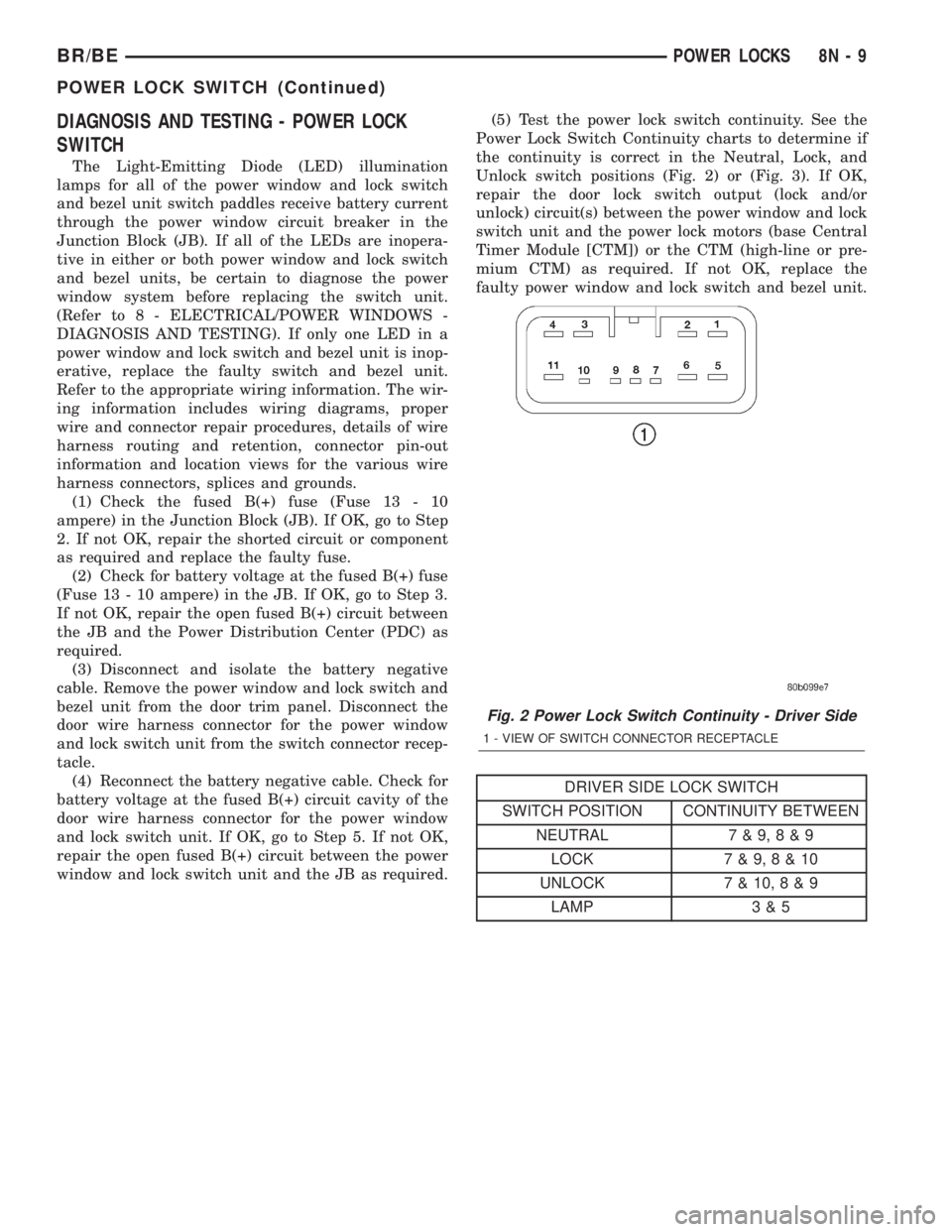
window and lock switch unit and the JB as required.(5) Test the power lock switch continuity. See the
Power Lock Switch Continuity charts to determine if
the continuity is correct in the Neutral, Lock, and
Unlock switch positions (Fig. 2) or (Fig. 3). If OK,
repair the door lock switch output (lock and/or
unlock) circuit(s) between the power window and lock
switch unit and the power lock motors (base Central
Timer Module [CTM]) or the CTM (high-line or pre-
mium CTM) as required. If not OK, replace the
faulty power window and lock switch and bezel unit.
DRIVER SIDE LOCK SWITCH
SWITCH POSITION CONTINUITY BETWEEN
NEUTRAL 7 & 9,8&9
LOCK 7 & 9,8&10
UNLOCK 7 & 10,8&9
LAMP 3 & 5
Fig. 2 Power Lock Switch Continuity - Driver Side
1 - VIEW OF SWITCH CONNECTOR RECEPTACLE
BR/BEPOWER LOCKS 8N - 9
POWER LOCK SWITCH (Continued)
Page 579 of 2255
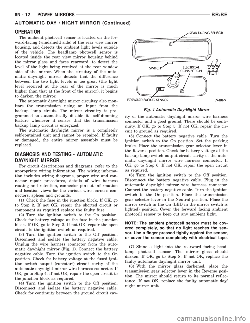
OPERATION
The ambient photocell sensor is located on the for-
ward-facing (windshield side) of the rear view mirror
housing, and detects the ambient light levels outside
of the vehicle. The headlamp photocell sensor is
located inside the rear view mirror housing behind
the mirror glass and faces rearward, to detect the
level of the light being received at the rear window
side of the mirror. When the circuitry of the auto-
matic day/night mirror detects that the difference
between the two light levels is too great (the light
level received at the rear of the mirror is much
higher than that at the front of the mirror), it begins
to darken the mirror.
The automatic day/night mirror circuitry also mon-
itors the transmission using an input from the
backup lamp circuit. The mirror circuitry is pro-
grammed to automatically disable its self-dimming
feature whenever it senses that the transmission
backup lamp circuit is energized.
The automatic day/night mirror is a completely
self-contained unit and cannot be repaired. If faulty
or damaged, the entire mirror assembly must be
replaced.
DIAGNOSIS AND TESTING - AUTOMATIC
DAY/NIGHT MIRROR
For circuit descriptions and diagrams, refer to the
appropriate wiring information. The wiring informa-
tion includes wiring diagrams, proper wire and con-
nector repair procedures, details of wire harness
routing and retention, connector pin-out information
and location views for the various wire harness con-
nectors, splices and grounds.
(1) Check the fuse in the junction block. If OK, go
to Step 2. If not OK, repair the shorted circuit or
component as required replace the faulty fuse.
(2) Turn the ignition switch to the On position.
Check for battery voltage at the fuse in the junction
block. If OK, go to Step 3. If not OK, repair the open
circuit to the ignition switch as required.
(3) Turn the ignition switch to the Off position.
Disconnect and isolate the battery negative cable.
Unplug the wire harness connector from the auto-
matic day/night mirror (Fig. 1). Connect the battery
negative cable. Turn the ignition switch to the On
position. Check for battery voltage at the fused igni-
tion switch output (run/start) circuit cavity of the
automatic day/night mirror wire harness connector. If
OK, go to Step 4. If not OK, repair the open circuit to
the junction block as required.
(4) Turn the ignition switch to the Off position.
Disconnect and isolate the battery negative cable.
Check for continuity between the ground circuit cav-ity of the automatic day/night mirror wire harness
connector and a good ground. There should be conti-
nuity. If OK, go to Step 5. If not OK, repair the cir-
cuit to ground as required.
(5) Connect the battery negative cable. Turn the
ignition switch to the On position. Set the parking
brake. Place the transmission gear selector lever in
the Reverse position. Check for battery voltage at the
backup lamp switch output circuit cavity of the auto-
matic day/night mirror wire harness connector. If
OK, go to Step 6. If not OK, repair the open circuit
as required.
(6) Turn the ignition switch to the Off position.
Disconnect the battery negative cable. Plug in the
automatic day/night mirror wire harness connector.
Connect the battery negative cable. Turn the ignition
switch to the On position. Place the transmission
gear selector lever in the Neutral position. Place the
mirror switch in the On (LED in the mirror switch is
lighted) position. Cover the forward facing ambient
photocell sensor to keep out any ambient light.
NOTE: The ambient photocell sensor must be cov-
ered completely, so that no light reaches the sen-
sor. Use a finger pressed tightly against the sensor,
or cover the sensor completely with electrical tape.
(7) Shine a light into the rearward facing head-
lamp photocell sensor. The mirror glass should
darken. If OK, go to Step 8. If not OK, replace the
faulty automatic day/night mirror unit.
(8) With the mirror glass darkened, place the
transmission gear selector lever in the Reverse posi-
tion. The mirror should return to its normal reflec-
tance. If not OK, replace the faulty automatic day/
night mirror unit.
Fig. 1 Automatic Day/Night Mirror
8N - 12 POWER MIRRORSBR/BE
AUTOMATIC DAY / NIGHT MIRROR (Continued)
Page 590 of 2255
POWER WINDOWS
TABLE OF CONTENTS
page page
POWER WINDOWS
DESCRIPTION.........................23
OPERATION...........................23
DIAGNOSIS AND TESTING - POWER
WINDOWS...........................23
POWER WINDOW SWITCH
DESCRIPTION.........................24
OPERATION...........................24
DIAGNOSIS AND TESTING - POWER
WINDOW SWITCH.....................24REMOVAL.............................25
INSTALLATION.........................26
WINDOW MOTOR
DESCRIPTION.........................26
DIAGNOSIS AND TESTING - WINDOW
MOTOR .............................26
REMOVAL.............................26
POWER WINDOWS
DESCRIPTION
Power windows are available as factory-installed
optional equipment on this model. The power lock
system is included on vehicles equipped with the
power window option.
OPERATION
The power window system allows each of the front
door windows to be raised and lowered electrically by
actuating a switch on the trim panel of each respec-
tive door. Additionally, the master switch on the
driver side door trim panel allows the driver to raise
or lower the passenger side front door window. The
power window system receives battery feed through a
circuit breaker in the junction block, only when the
ignition switch is in the On position.
The power window system includes the power win-
dow switches on each front door trim panel, the cir-
cuit breaker in the junction block, and the power
window motors inside each front door. This group
covers diagnosis and service of only the electrical
components in the power window system. For service
of mechanical components, such as the regulator, lift
plate, window tracks, or glass refer to Group 23 -
Body.
Refer to the owner's manual in the vehicle glove
box for more information on the features, use and
operation of the power window system.
DIAGNOSIS AND TESTING - POWER
WINDOWS
For circuit descriptions and diagrams, refer to the
appropriate wiring information. The wiring informa-
tion includes wiring diagrams, proper wire and con-
nector repair procedures, details of wire harnessrouting and retention, connector pin-out information
and location views for the various wire harness con-
nectors, splices and grounds.
ALL WINDOWS INOPERATIVE
(1) Check the circuit breaker in the junction block.
If OK, go to Step 2. If not OK, replace the faulty cir-
cuit breaker.
(2) Disconnect and isolate the battery negative
cable. Remove the power window and lock switch and
bezel unit from the driver side front door trim panel.
Unplug the wire harness connector from the switch
and bezel unit.
(3) Check for continuity between the ground cir-
cuit cavity of the switch and bezel unit wire harness
connector and a good ground. If OK, (Refer to 8 -
ELECTRICAL/POWER WINDOWS/POWER WIN-
DOW SWITCH - DIAGNOSIS AND TESTING). If not
OK, repair the circuit to ground as required.
ONE WINDOW INOPERATIVE
The window glass must be free to slide up and
down for the power window motor to function prop-
erly. If the glass is not free to move up and down, the
motor will overload and trip the integral circuit
breaker. To determine if the glass is free, disconnect
the regulator plate from the glass. Then slide the
window up and down by hand.
There is an alternate method to check if the glass
is free. Position the glass between the up and down
stops. Then, shake the glass in the door. Check that
the glass can be moved slightly from side to side,
front to rear, and up and down. Then check that the
glass is not bound tight in the tracks. If the glass is
free, proceed with the diagnosis that follows. If the
glass is not free, (Refer to 23 - BODY/DOOR -
FRONT/DOOR GLASS - REMOVAL).
BR/BEPOWER WINDOWS 8N - 23
Page 591 of 2255
(1) Disconnect and isolate the battery negative
cable. Remove the power window and lock switch and
bezel unit from the door trim panel on the side of the
vehicle with the inoperative window. Unplug the wire
harness connector from the switch and bezel unit.
(2) Connect the battery negative cable. Turn the
ignition switch to the On position. Check for battery
voltage at the fused ignition switch output (run) cir-
cuit cavity in the body half of the switch and bezel
unit wire harness connector. If OK, and the inopera-
tive power window is on the driver side, go to Step 4.
If OK, and the inoperative power window is on the
passenger side, go to Step 3. If not OK, repair the
open circuit to the junction block as required.
(3) Disconnect and isolate the battery negative
cable. Check for continuity between each of the two
master window switch right up/down control circuit
cavities in the body half of the passenger side switch
and bezel unit wire harness connector and a good
ground. In each case, there should be continuity. If
OK, go to Step 4. If not OK, repair the open circuit to
the driver side switch and bezel unit as required.
(4) Test the power window switch continuity.
(Refer to 8 - ELECTRICAL/POWER WINDOWS/
POWER WINDOW SWITCH - DIAGNOSIS AND
TESTING). If OK, go to Step 5. If not OK, replace
the faulty power window and lock switch and bezel
unit.
(5) Refer to the appropriate wiring information.
The wiring information includes wiring diagrams,
proper wire and connector repair procedures, details
of wire harness routing and retention, connector pin-
out information and location views for the various
wire harness connectors, splices and grounds. Check
the continuity in each circuit between the inoperative
power window and lock switch and bezel unit wire
harness connector cavities and the corresponding
power window motor wire harness connector cavities.
If OK, (Refer to 8 - ELECTRICAL/POWER WIN-
DOWS/WINDOW MOTOR - DIAGNOSIS AND TEST-
ING). If not OK, repair the open circuit(s) as
required.
NOTE: The passenger side power window switch
receives the ground feed for operating the passen-
ger side power window motor through the driver
side power window switch and wire harness con-
nector.
POWER WINDOW SWITCH
DESCRIPTION
The power windows are controlled by two-way
switches integral to the power window and lock
switch and bezel unit on the trim panel of each frontdoor. A second power window switch in the driver
side switch and bezel unit allows the driver to control
the passenger side window. A Light-Emitting Diode
(LED) in the paddle of each switch is illuminated
whenever the ignition switch is in the On position.
OPERATION
The power window switch for the driver side front
door has an Auto label on it. This switch has a sec-
ond detent position beyond the normal Down position
that provides an automatic one-touch window down
feature. This feature is controlled by an electronic
circuit and a relay that are integral to the driver side
front door power window and lock switch unit.
The power window switches control the battery
and ground feeds to the power window motors. The
passenger side power window switch receives a
ground feed through the driver side power window
switch for operating the passenger side power win-
dow motor.
The power window and lock switch and bezel unit
cannot be repaired and, if faulty or damaged, the
entire switch and bezel unit must be replaced.
DIAGNOSIS AND TESTING - POWER WINDOW
SWITCH
The auto down feature of the driver side power
window switch is controlled by an electronic circuit
within the switch unit. The auto down circuitry is
activated when the driver side power window switch
is moved to the second detent in the Down direction.
The outputs from the auto down circuitry are carried
through the same switch pins that provide the nor-
mal down function. The auto down circuit cannot be
tested. If the driver side power window switch conti-
nuity tests are passed, but the auto down feature is
inoperative, replace the faulty driver side power win-
dow switch unit.
The Light-Emitting Diode (LED) illumination
lamps for all of the power window and lock switch
and bezel unit switch paddles receive battery current
through the power window circuit breaker in the
junction block. If all of the LEDs are inoperative in
either or both power window and lock switch and
bezel units and the power windows are inoperative,
perform the diagnosis for Power Window System in
this group. If the power windows operate, but any or
all of the LEDs are inoperative, the power window
and lock switch and bezel unit with the inoperative
LED(s) is faulty and must be replaced. For circuit
descriptions and diagrams, refer to the appropriate
wiring information. The wiring information includes
wiring diagrams, proper wire and connector repair
procedures, details of wire harness routing and
retention, connector pin-out information and location
8N - 24 POWER WINDOWSBR/BE
POWER WINDOWS (Continued)