DODGE RAM 2003 Service Owner's Guide
Manufacturer: DODGE, Model Year: 2003, Model line: RAM, Model: DODGE RAM 2003Pages: 2895, PDF Size: 83.15 MB
Page 31 of 2895
OPERATION
²CASTERis the forward or rearward tilt of the
steering knuckle from vertical. Tilting the top of the
knuckle forward provides less positive caster. Tilting
the top of the knuckle rearward provides more posi-
tive caster. Positive caster promotes directional sta-
bility. This angle enables the front wheels to return
to a straight ahead position after turns (Fig. 1)
²CAMBERis the inward or outward tilt of the
wheel relative to the center of the vehicle. Tilting the
top of the wheel inward provides negative camber.
Tilting the top of the wheel outward provides positive
camber. Incorrect camber will cause wear on the
inside or outside edge of the tire (Fig. 1)
²TOEis the difference between the leading inside
edges and trailing inside edges of the front tires.
Wheel toe position out of specification cause's unsta-
ble steering, uneven tire wear and steering wheel off-
center. The wheel toe position is thefinalfront
wheel alignment adjustment (Fig. 1)
²THRUST ANGLEis the angle of the rear axle
relative to the centerline of the vehicle. Incorrect
thrust angle can cause off-center steering and exces-sive tire wear. This angle is not adjustable, damaged
component(s) must be replaced to correct the thrust
angle (Fig. 1)
DIAGNOSIS AND TESTING - PRE-ALIGNMENT
INSPECTION
Before starting wheel alignment, the following
inspection and necessary corrections must be com-
pleted. Refer to Suspension and Steering System
Diagnosis Chart below for additional information.
(1) Inspect tires for size, air pressure and tread
wear.
(2) Inspect front wheel bearings for wear.
(3) Inspect front wheels for excessive radial or lat-
eral runout and balance.
(4) Inspect ball studs, linkage pivot points and
steering gear for looseness, roughness or binding.
(5) Inspect suspension components for wear and
noise.
(6) On 4x4 vehicles check suspension height (LD
only).
(7) Road test the vehicle.
SUSPENSION AND STEERING SYSTEM DIAGNOSIS
CONDITION POSSIBLE CAUSES CORRECTION
FRONT END NOISE 1. Loose or worn wheel bearing. 1. Replace wheel bearing.
2. Loose or worn steering or
suspension components.2. Tighten or replace components as
necessary.
3. Loose or worn steering or
suspension components.3. Tighten or replace components as
necessary.
EXCESSIVE PLAY IN
STEERING1. Loose or worn wheel bearing. 1. Replace wheel bearing.
2. Loose or worn steering or
suspension components.2. Tighten or replace components as
necessary.
3. Loose or worn steering gear. 3. Replace steering gear.
FRONT WHEELS SHIMMY 1. Loose or worn wheel bearing. 1. Replace wheel bearing.
2. Loose or worn steering or
suspension components.2. Tighten or replace components as
necessary.
3. Tires worn or out of balance. 3. Replace or balance tires.
4. Alignment. 4. Align vehicle to specifications.
VEHICLE INSTABILITY 1. Loose or worn wheel bearing. 1. Replace wheel bearing.
2. Loose or worn steering or
suspension components.2. Tighten or replace components as
necessary.
3. Tire pressure. 3. Adjust tire pressure.
4. Alignment. 4. Align vehicle to specifications.
2 - 2 WHEEL ALIGNMENTDR
WHEEL ALIGNMENT (Continued)
Page 32 of 2895
CONDITION POSSIBLE CAUSES CORRECTION
EXCESSIVE STEERING
EFFORT1. Loose or worn steering gear. 1. Replace steering gear.
2. Column coupler binding. 2. Replace coupler.
3. Tire pressure. 3. Adjust tire pressure.
4. Alignment. 4. Align vehicle to specifications.
VEHICLE PULLS TO ONE
SIDE1. Tire pressure. 1. Adjust tire pressure.
2. Tire. 2. Criss-Cross Front Tires.
3. Alignment. 3. Align vehicle to specifications.
4. Loose or worn steering or
suspension components.4. Tighten or replace components as
necessary.
5. Radial tire lead. 5. Rotate or replace tire as necessary.
6. Brake pull. 6. Repair brake as necessary.
7. Weak or broken spring. 7. Replace spring.
8. Ride height (LD) 4WD only. 8. Measure and adjust ride height. (LD
only)
STANDARD PROCEDURE
STANDARD PROCEDURE - HEIGHT
MEASUREMENT - 4WD (LD)
The vehicle suspension height MUST be measured
and adjusted before performing wheel alignment pro-
cedure. Also when front suspension components have
been replaced. This measure must be performed with
the vehicle supporting it's own weight and taken on
both sides of the vehicle.
(1) Inspect tires and set to correct pressure.
(2) Jounce the front of the vehicle.
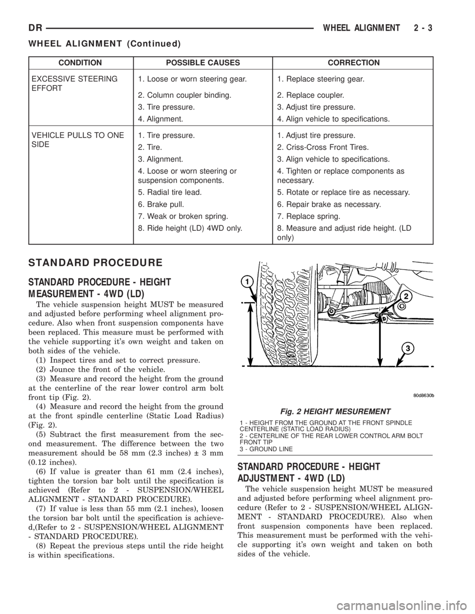
(3) Measure and record the height from the ground
at the centerline of the rear lower control arm bolt
front tip (Fig. 2).
(4) Measure and record the height from the ground
at the front spindle centerline (Static Load Radius)
(Fig. 2).
(5) Subtract the first measurement from the sec-
ond measurement. The difference between the two
measurement should be 58 mm (2.3 inches) 3mm
(0.12 inches).
(6) If value is greater than 61 mm (2.4 inches),
tighten the torsion bar bolt until the specification is
achieved (Refer to 2 - SUSPENSION/WHEEL
ALIGNMENT - STANDARD PROCEDURE).
(7) If value is less than 55 mm (2.1 inches), loosen
the torsion bar bolt until the specification is achieve-
d,(Refer to 2 - SUSPENSION/WHEEL ALIGNMENT
- STANDARD PROCEDURE).
(8) Repeat the previous steps until the ride height
is within specifications.
STANDARD PROCEDURE - HEIGHT
ADJUSTMENT - 4WD (LD)
The vehicle suspension height MUST be measured
and adjusted before performing wheel alignment pro-
cedure (Refer to 2 - SUSPENSION/WHEEL ALIGN-
MENT - STANDARD PROCEDURE). Also when
front suspension components have been replaced.
This measurement must be performed with the vehi-
cle supporting it's own weight and taken on both
sides of the vehicle.
Fig. 2 HEIGHT MESUREMENT
1 - HEIGHT FROM THE GROUND AT THE FRONT SPINDLE
CENTERLINE (STATIC LOAD RADIUS)
2 - CENTERLINE OF THE REAR LOWER CONTROL ARM BOLT
FRONT TIP
3 - GROUND LINE
DRWHEEL ALIGNMENT 2 - 3
WHEEL ALIGNMENT (Continued)
Page 33 of 2895
To adjust the vehicle height turn the torsion bar
adjustment bolt CLOCKWISE to raise the vehicle
and COUNTER CLOCKWISE to lower the vehicle.
CAUTION: ALWAYS raise the vehicle to the correct
suspension height, NEVER lower the vehicle to
obtain the correct suspension height. If the vehicle
suspension height is too high, lower the vehicle
below the height specification. Then raise the vehi-
cle to the correct suspension height specification.
This will insure the vehicle maintains the proper
suspension height.
NOTE: If a height adjustment has been made, per-
form height measurement again on both sides of
the vehicle.
STANDARD PROCEDURE - CAMBER AND
CASTER ADJUSTMENT
NOTE: 4X4 (LD) SUSPENSION HEIGHT MEASURE-
MENT MUST BE PERFORMED BEFORE AN ALIGN-
MENT.
NOTE: When the upper control arm pivot bolts are
loosened the upper control arm will normally go
inwards toward the frame automatically with the
weight of the vehicle.
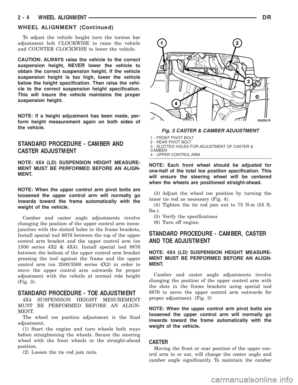
Camber and caster angle adjustments involve
changing the position of the upper control arm incon-
junction with the slotted holes in the frame brackets,
Install special tool 8876 between the top of the upper
control arm bracket and the upper control arm (on
1500 series 4X2 & 4X4). Install special tool 8876
between the bottom of the upper control arm bracket
pressing the tool against the frame and the upper
control arm (on 2500/3500 series 4X2) in order to
move the upper control arm outwards for proper
adjustment with the vehicle at normal ride height
(Fig. 3).
STANDARD PROCEDURE - TOE ADJUSTMENT
4X4 SUSPENSION HEIGHT MESUREMENT
MUST BE PERFORMED BEFORE AN ALIGN-
MENT.
The wheel toe position adjustment is the final
adjustment.
(1) Start the engine and turn wheels both ways
before straightening the wheels. Secure the steering
wheel with the front wheels in the straight-ahead
position.
(2) Loosen the tie rod jam nuts.NOTE: Each front wheel should be adjusted for
one-half of the total toe position specification. This
will ensure the steering wheel will be centered
when the wheels are positioned straight-ahead.
(3) Adjust the wheel toe position by turning the
inner tie rod as necessary (Fig. 4).
(4) Tighten the tie rod jam nut to 75 N´m (55 ft.
lbs.).
(5) Verify the specifications
(6) Turn off engine.
STANDARD PROCEDURE - CAMBER, CASTER
AND TOE ADJUSTMENT
NOTE: 4X4 (LD) SUSPENSION HEIGHT MEASURE-
MENT MUST BE PERFORMED BEFORE AN ALIGN-
MENT.
Camber and caster angle adjustments involve
changing the position of the upper control arm with
the slots in the frame brackets using special tool
8876 to move the upper control arm outwards for
proper adjustment. (Fig. 3)
NOTE: When the upper control arm pivot bolts are
loosened the upper control arm will normally go
inwards toward the frame automatically with the
weight of the vehicle.
CASTER
Moving the front or rear position of the upper con-
trol arm in or out, will change the caster angle and
camber angle significantly. To maintain the camber
Fig. 3 CASTER & CAMBER ADJUSTMENT
1 - FRONT PIVOT BOLT
2 - REAR PIVOT BOLT
3 - SLOTTED HOLES FOR ADJUSTMENT OF CASTER &
CAMBER
4 - UPPER CONTROL ARM
2 - 4 WHEEL ALIGNMENTDR
WHEEL ALIGNMENT (Continued)
Page 34 of 2895
angle while adjusting caster, move one pivot bolt of
the upper control arm in or out. Then move the other
pivot bolt of the upper control arm in the opposite
direction. Install special tool 8876 between the top of
the upper control arm bracket and the upper control
arm (on 1500 series 4X2 & 4X4). Install special tool
8876 between the bottom of the upper control arm
bracket pressing the tool against the frame and the
upper control arm (on 2500/3500 series 4X2) in order
to move the upper control arm outwards for proper
adjustment with the vehicle at normal ride height
(Fig. 3).
To increase positive caster angle, move the rear
position of the upper control arm inward (toward the
engine). Move the front of the upper control arm out-
ward (away from the engine) slightly until the origi-
nal camber angle is obtained using special tool 8876
to move the upper control arm for proper adjustment.
(Fig. 3)
CAMBER
Move both pivot bolts of the upper control arm
together in or out. This will change the camber angle
significantly and little effect on the caster angle
using special tool 8876 to move the upper control
arm for proper adjustment. (Fig. 3)
After adjustment is made tighten the upper control
arm nuts to proper torque specification.
TOE ADJUSTMENT
The wheel toe position adjustment is the final
adjustment.
(1) Start the engine and turn wheels both ways
before straightening the wheels. Secure the steering
wheel with the front wheels in the straight-ahead
position.
(2) Loosen the tie rod jam nuts.
NOTE: Each front wheel should be adjusted for
one-half of the total toe position specification. This
will ensure the steering wheel will be centered
when the wheels are positioned straight-ahead.
(3) Adjust the wheel toe position by turning the
inner tie rod as necessary (Fig. 4).
(4) Tighten the tie rod jam nut to 75 N´m (55 ft.
lbs.).
(5) Verify the specifications
(6) Turn off engine.
STANDARD PROCEDURE - ALIGNMENT
LINK/COIL SUSPENSION
Before each alignment reading the vehicle should
be jounced (rear first, then front). Grasp each
bumper at the center and jounce the vehicle up and
down several times. Always release the bumper inthe down position.Set the front end alignment to
specifications while the vehicle is in its NOR-
MALLY LOADED CONDITION.
CAMBER:The wheel camber angle is preset and
is not adjustable.
CASTER:Check the caster of the front axle for
correct angle. Be sure the axle is not bent or twisted.
Road test the vehicle and make left and right turn.
Observe the steering wheel return-to-center position.
Low caster will cause poor steering wheel returnabil-
ity.
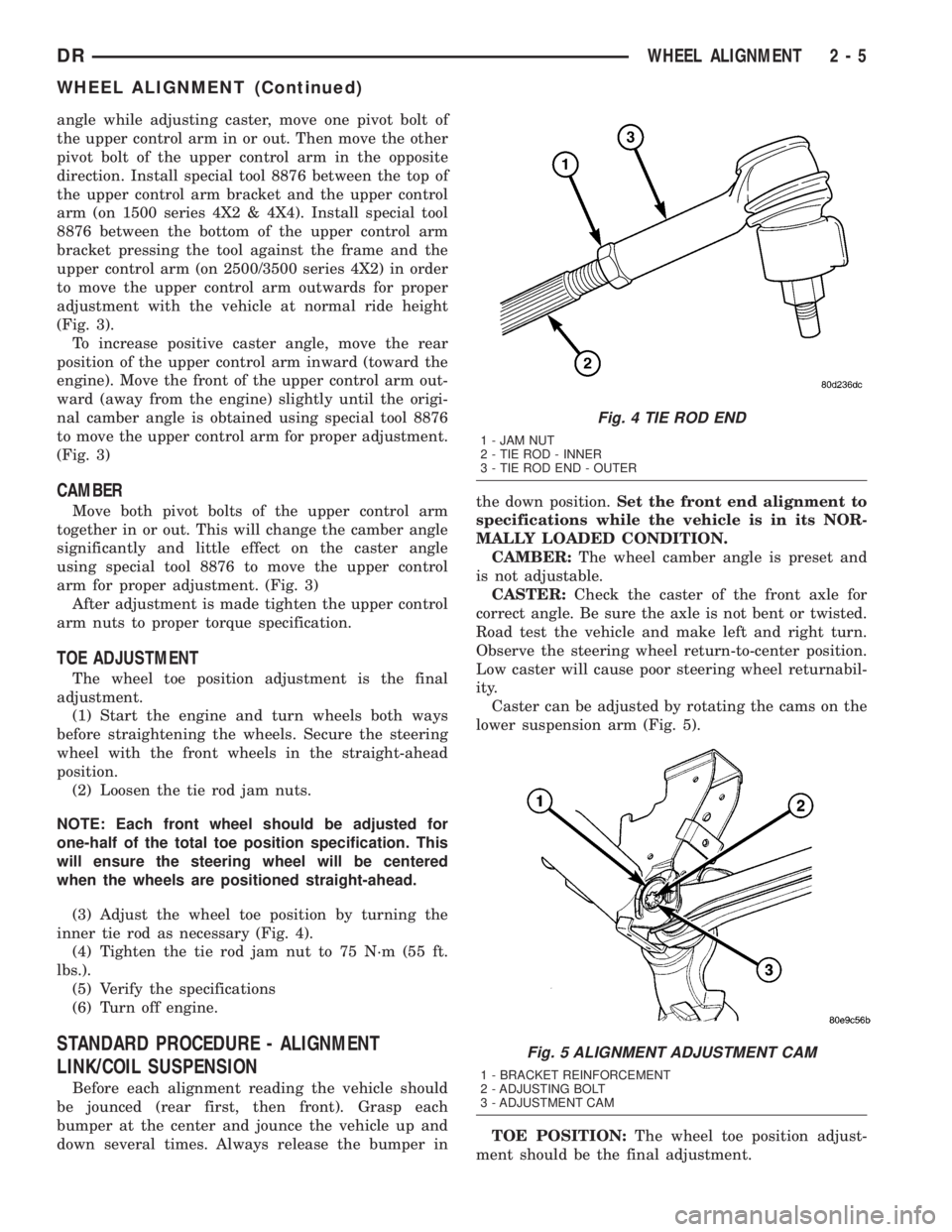
Caster can be adjusted by rotating the cams on the
lower suspension arm (Fig. 5).
TOE POSITION:The wheel toe position adjust-
ment should be the final adjustment.
Fig. 4 TIE ROD END
1 - JAM NUT
2 - TIE ROD - INNER
3 - TIE ROD END - OUTER
Fig. 5 ALIGNMENT ADJUSTMENT CAM
1 - BRACKET REINFORCEMENT
2 - ADJUSTING BOLT
3 - ADJUSTMENT CAM
DRWHEEL ALIGNMENT 2 - 5
WHEEL ALIGNMENT (Continued)
Page 35 of 2895
(1) Start the engine and turn wheels both ways
before straightening the wheels. Center and Secure
the steering wheel and turn off engine.
(2) Loosen the adjustment sleeve clamp bolts.
(3) Adjust the right wheel toe position with the
drag link. Turn the sleeve until the right wheel is at
the correct TOE-IN position. Position clamp bolts to
their original position and tighten to specifications.
Make sure the toe setting does not change dur-
ing clamp tightening.
(4) Adjust left wheel toe position with tie rod at
left knuckle. Turn the sleeve until the left wheel is at
the correct TOE-IN position. Position clamp bolts to
their original position and tighten to specifications.
Make sure the toe setting does not change dur-
ing clamp tightening.
(5) Verify the right toe setting and a straight steer-
ing wheel.
(6) Road test the vehicle.
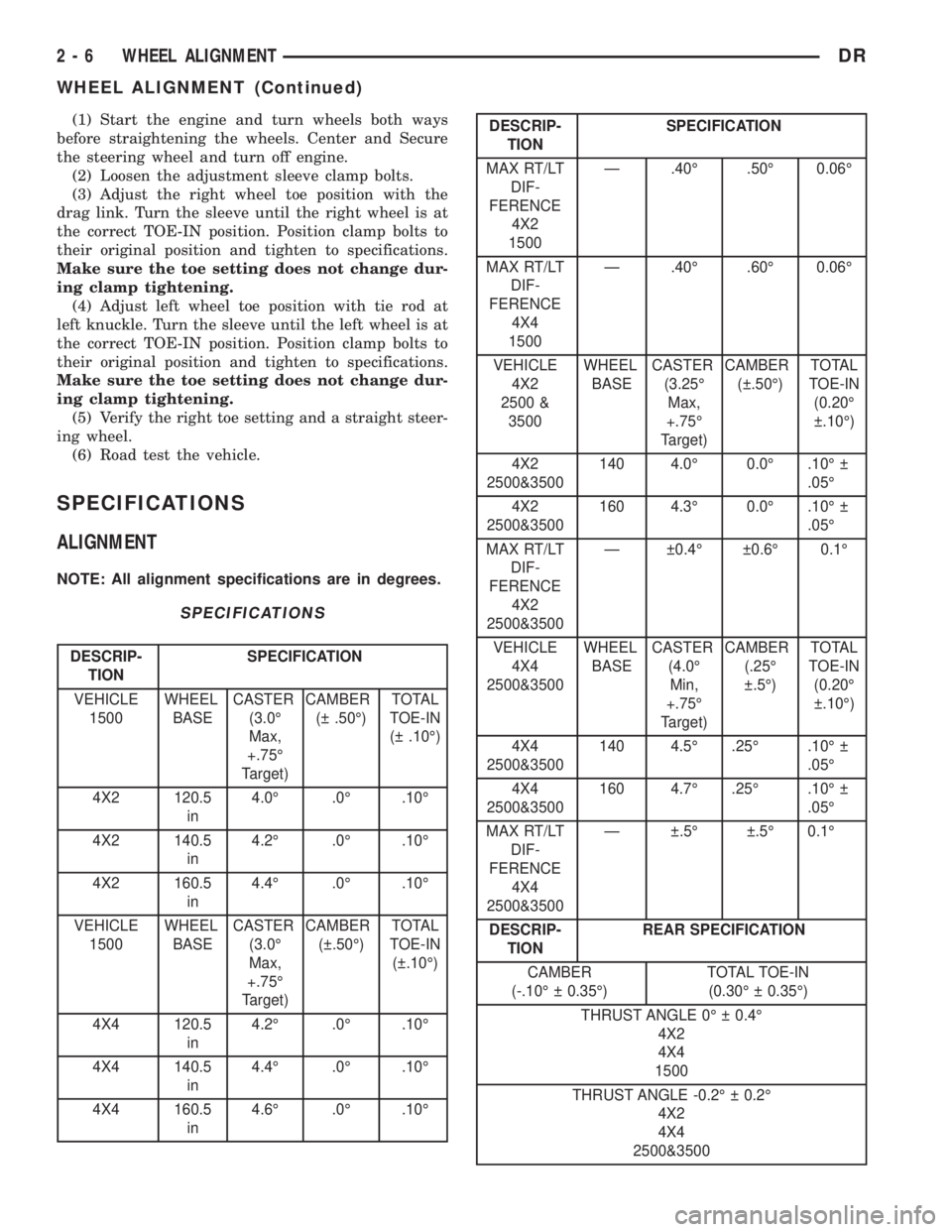
SPECIFICATIONS
ALIGNMENT
NOTE: All alignment specifications are in degrees.
SPECIFICATIONS
DESCRIP-
TIONSPECIFICATION
VEHICLE
1500WHEEL
BASECASTER
(3.0É
Max,
+.75É
Target)CAMBER
( .50É)TOTAL
TOE-IN
( .10É)
4X2 120.5
in4.0É .0É .10É
4X2 140.5
in4.2É .0É .10É
4X2 160.5
in4.4É .0É .10É
VEHICLE
1500WHEEL
BASECASTER
(3.0É
Max,
+.75É
Target)CAMBER
( .50É)TOTAL
TOE-IN
( .10É)
4X4 120.5
in4.2É .0É .10É
4X4 140.5
in4.4É .0É .10É
4X4 160.5
in4.6É .0É .10É
DESCRIP-
TIONSPECIFICATION
MAX RT/LT
DIF-
FERENCE
4X2
1500Ð .40É .50É 0.06É
MAX RT/LT
DIF-
FERENCE
4X4
1500Ð .40É .60É 0.06É
VEHICLE
4X2
2500 &
3500WHEEL
BASECASTER
(3.25É
Max,
+.75É
Target)CAMBER
( .50É)TOTAL
TOE-IN
(0.20É
.10É)
4X2
2500&3500140 4.0É 0.0É .10É
.05É
4X2
2500&3500160 4.3É 0.0É .10É
.05É
MAX RT/LT
DIF-
FERENCE
4X2
2500&3500Ð 0.4É 0.6É 0.1É
VEHICLE
4X4
2500&3500WHEEL
BASECASTER
(4.0É
Min,
+.75É
Target)CAMBER
(.25É
.5É)TOTAL
TOE-IN
(0.20É
.10É)
4X4
2500&3500140 4.5É .25É .10É
.05É
4X4
2500&3500160 4.7É .25É .10É
.05É
MAX RT/LT
DIF-
FERENCE
4X4
2500&3500Ð .5É .5É 0.1É
DESCRIP-
TIONREAR SPECIFICATION
CAMBER
(-.10É 0.35É)TOTAL TOE-IN
(0.30É 0.35É)
THRUST ANGLE 0É 0.4É
4X2
4X4
1500
THRUST ANGLE -0.2É 0.2É
4X2
4X4
2500&3500
2 - 6 WHEEL ALIGNMENTDR
WHEEL ALIGNMENT (Continued)
Page 36 of 2895
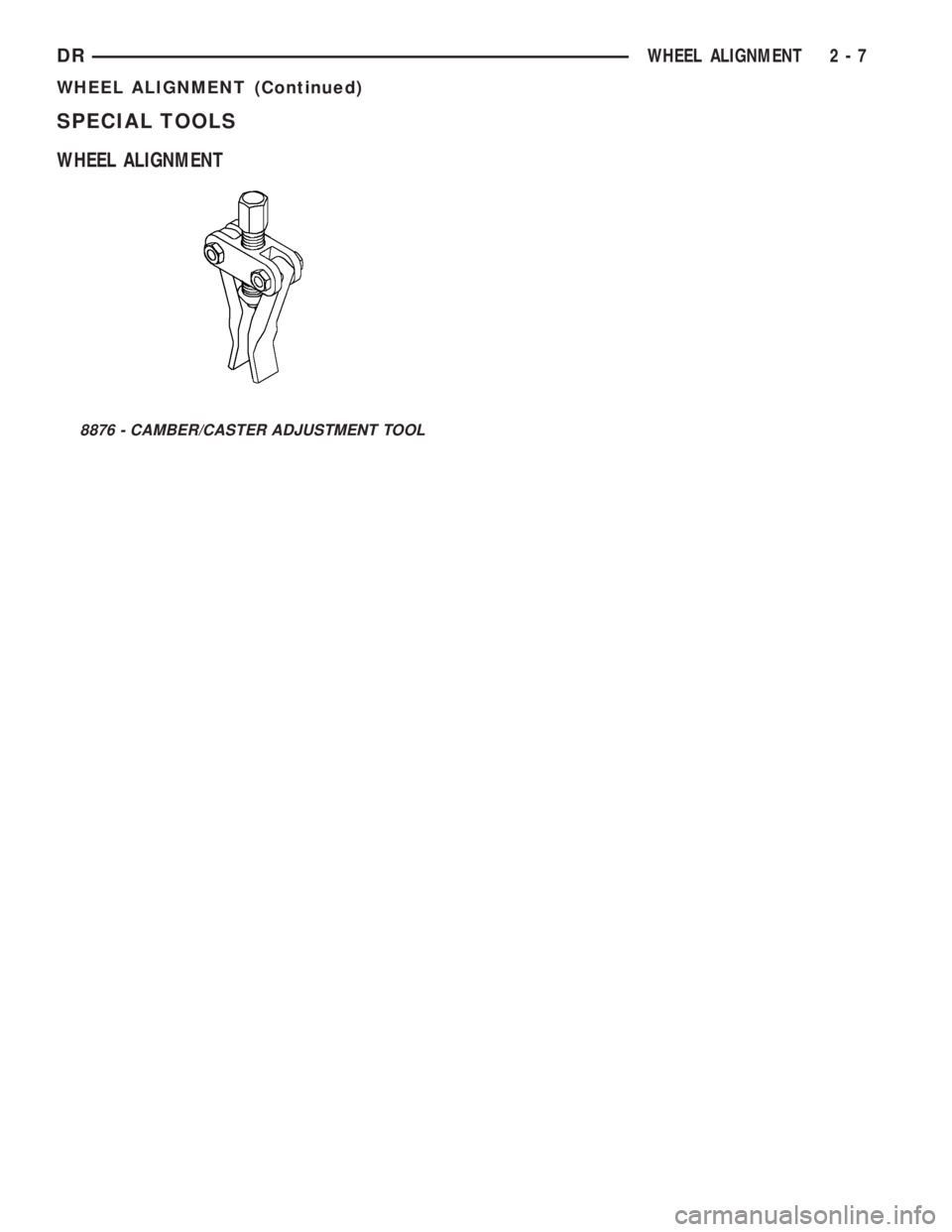
SPECIAL TOOLS
WHEEL ALIGNMENT
8876 - CAMBER/CASTER ADJUSTMENT TOOL
DRWHEEL ALIGNMENT 2 - 7
WHEEL ALIGNMENT (Continued)
Page 37 of 2895
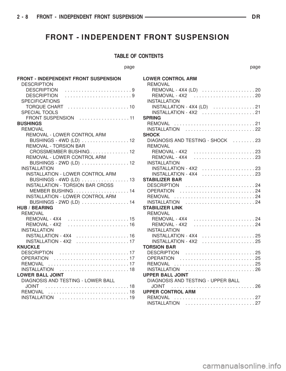
FRONT - INDEPENDENT FRONT SUSPENSION
TABLE OF CONTENTS
page page
FRONT - INDEPENDENT FRONT SUSPENSION
DESCRIPTION
DESCRIPTION........................9
DESCRIPTION........................9
SPECIFICATIONS
TORQUE CHART......................10
SPECIAL TOOLS
FRONT SUSPENSION..................11
BUSHINGS
REMOVAL
REMOVAL - LOWER CONTROL ARM
BUSHINGS - 4WD (LD).................12
REMOVAL - TORSION BAR
CROSSMEMBER BUSHING..............12
REMOVAL - LOWER CONTROL ARM
BUSHINGS - 2WD (LD).................12
INSTALLATION
INSTALLATION - LOWER CONTROL ARM
BUSHINGS - 4WD (LD).................13
INSTALLATION - TORSION BAR CROSS
MEMBER BUSHING....................14
INSTALLATION - LOWER CONTROL ARM
BUSHINGS - 2WD (LD).................14
HUB / BEARING
REMOVAL
REMOVAL - 4X4......................15
REMOVAL - 4X2......................16
INSTALLATION
INSTALLATION - 4X4...................16
INSTALLATION - 4X2...................17
KNUCKLE
DESCRIPTION.........................17
OPERATION...........................17
REMOVAL.............................17
INSTALLATION.........................18
LOWER BALL JOINT
DIAGNOSIS AND TESTING - LOWER BALL
JOINT..............................18
REMOVAL.............................18
INSTALLATION.........................19LOWER CONTROL ARM
REMOVAL
REMOVAL - 4X4 (LD)...................20
REMOVAL - 4X2......................20
INSTALLATION
INSTALLATION - 4X4 (LD)...............21
INSTALLATION - 4X2...................21
SPRING
REMOVAL.............................21
INSTALLATION.........................22
SHOCK
DIAGNOSIS AND TESTING - SHOCK........23
REMOVAL
REMOVAL - 4X2......................23
REMOVAL - 4X4......................23
INSTALLATION
INSTALLATION - 4X2...................23
INSTALLATION - 4X4...................23
STABILIZER BAR
DESCRIPTION.........................24
OPERATION...........................24
REMOVAL.............................24
INSTALLATION.........................24
STABILIZER LINK
REMOVAL
REMOVAL - 4X4......................24
REMOVAL - 4X2......................24
INSTALLATION
INSTALLATION - 4X4...................25
INSTALLATION - 4X2...................25
TORSION BAR
DESCRIPTION.........................25
OPERATION...........................25
REMOVAL.............................25
INSTALLATION.........................26
UPPER BALL JOINT
DIAGNOSIS AND TESTING - UPPER BALL
JOINT..............................26
UPPER CONTROL ARM
REMOVAL.............................27
INSTALLATION.........................27
2 - 8 FRONT - INDEPENDENT FRONT SUSPENSIONDR
Page 38 of 2895
FRONT - INDEPENDENT
FRONT SUSPENSION
DESCRIPTION
DESCRIPTION
The front suspension is designed to allow each
wheel to adapt to different road surfaces indepen-
dently. The wheels are mounted to hub/bearings
units bolted to the steering knuckle. The double-row
hub bearings are sealed and lubricated for life. The
steering knuckles turn (pivot) on ball joints.
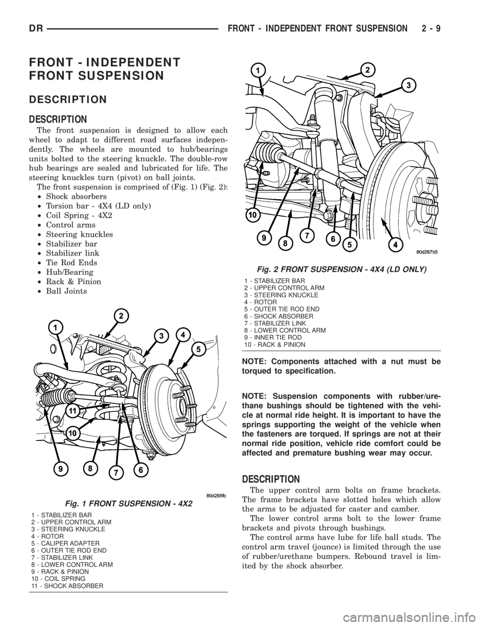
The front suspension is comprised of (Fig. 1) (Fig. 2):
²Shock absorbers
²Torsion bar - 4X4 (LD only)
²Coil Spring - 4X2
²Control arms
²Steering knuckles
²Stabilizer bar
²Stabilizer link
²Tie Rod Ends
²Hub/Bearing
²Rack & Pinion
²Ball Joints
NOTE: Components attached with a nut must be
torqued to specification.
NOTE: Suspension components with rubber/ure-
thane bushings should be tightened with the vehi-
cle at normal ride height. It is important to have the
springs supporting the weight of the vehicle when
the fasteners are torqued. If springs are not at their
normal ride position, vehicle ride comfort could be
affected and premature bushing wear may occur.
DESCRIPTION
The upper control arm bolts on frame brackets.
The frame brackets have slotted holes which allow
the arms to be adjusted for caster and camber.
The lower control arms bolt to the lower frame
brackets and pivots through bushings.
The control arms have lube for life ball studs. The
control arm travel (jounce) is limited through the use
of rubber/urethane bumpers. Rebound travel is lim-
ited by the shock absorber.
Fig. 1 FRONT SUSPENSION - 4X2
1 - STABILIZER BAR
2 - UPPER CONTROL ARM
3 - STEERING KNUCKLE
4 - ROTOR
5 - CALIPER ADAPTER
6 - OUTER TIE ROD END
7 - STABILIZER LINK
8 - LOWER CONTROL ARM
9 - RACK & PINION
10 - COIL SPRING
11 - SHOCK ABSORBER
Fig. 2 FRONT SUSPENSION - 4X4 (LD ONLY)
1 - STABILIZER BAR
2 - UPPER CONTROL ARM
3 - STEERING KNUCKLE
4 - ROTOR
5 - OUTER TIE ROD END
6 - SHOCK ABSORBER
7 - STABILIZER LINK
8 - LOWER CONTROL ARM
9 - INNER TIE ROD
10 - RACK & PINION
DRFRONT - INDEPENDENT FRONT SUSPENSION 2 - 9
Page 39 of 2895
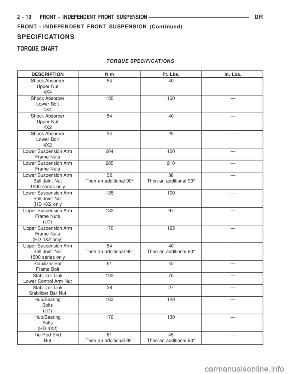
SPECIFICATIONS
TORQUE CHART
TORQUE SPECIFICATIONS
DESCRIPTION N´m Ft. Lbs. In. Lbs.
Shock Absorber
Upper Nut
4X454 40 Ð
Shock Absorber
Lower Bolt
4X4135 100 Ð
Shock Absorber
Upper Nut
4X254 40 Ð
Shock Absorber
Lower Bolt
4X234 25 Ð
Lower Suspension Arm
Frame Nuts204 150 Ð
Lower Suspension Arm
Frame Nuts285 210 Ð
Lower Suspension Arm
Ball Joint Nut
1500 series only52
Then an additional 90É38
Then an additional 90ÉÐ
Lower Suspension Arm
Ball Joint Nut
(HD 4X2 only135 100 Ð
Upper Suspension Arm
Frame Nuts
(LD)132 97 Ð
Upper Suspension Arm
Frame Nuts
(HD 4X2 only)170 125 Ð
Upper Suspension Arm
Ball Joint Nut
1500 series only54
Then an additional 90É40
Then an additional 90ÉÐ
Stabilizer Bar
Frame Bolt61 45 Ð
Stabilizer Link
Lower Control Arm Nut102 75 Ð
Stabilizer Link
Stabilizer Bar Nut38 27 Ð
Hub/Bearing
Bolts
(LD)163 120 Ð
Hub/Bearing
Bolts
(HD 4X2)176 130 Ð
Tie Rod End
Nut61
Then an additional 90É45
Then an additional 90ÉÐ
2 - 10 FRONT - INDEPENDENT FRONT SUSPENSIONDR
FRONT - INDEPENDENT FRONT SUSPENSION (Continued)
Page 40 of 2895
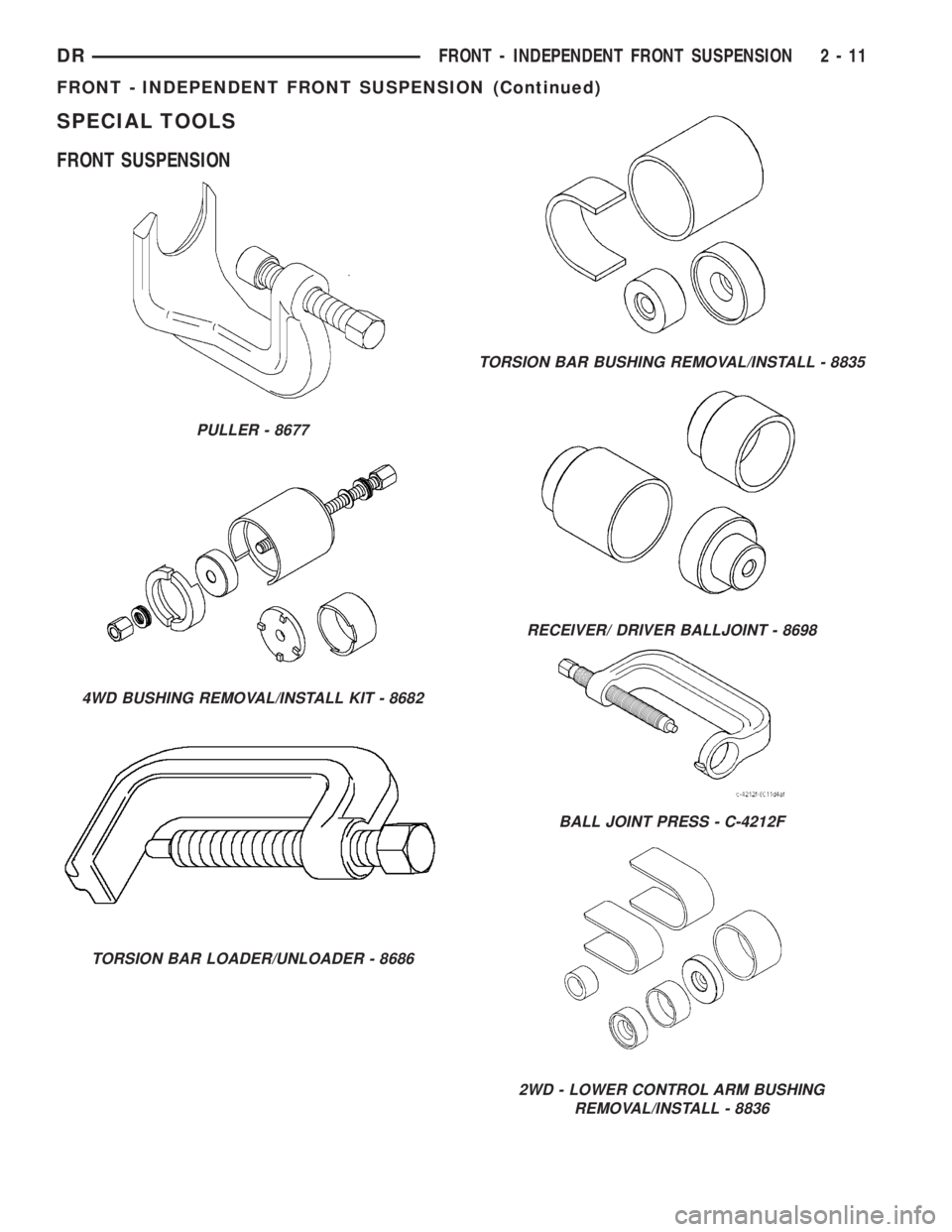
SPECIAL TOOLS
FRONT SUSPENSION
PULLER - 8677
4WD BUSHING REMOVAL/INSTALL KIT - 8682
TORSION BAR LOADER/UNLOADER - 8686
TORSION BAR BUSHING REMOVAL/INSTALL - 8835
RECEIVER/ DRIVER BALLJOINT - 8698
BALL JOINT PRESS - C-4212F
2WD - LOWER CONTROL ARM BUSHING
REMOVAL/INSTALL - 8836
DRFRONT - INDEPENDENT FRONT SUSPENSION 2 - 11
FRONT - INDEPENDENT FRONT SUSPENSION (Continued)