bushing DODGE RAM 2003 Service Repair Manual
[x] Cancel search | Manufacturer: DODGE, Model Year: 2003, Model line: RAM, Model: DODGE RAM 2003Pages: 2895, PDF Size: 83.15 MB
Page 2261 of 2895
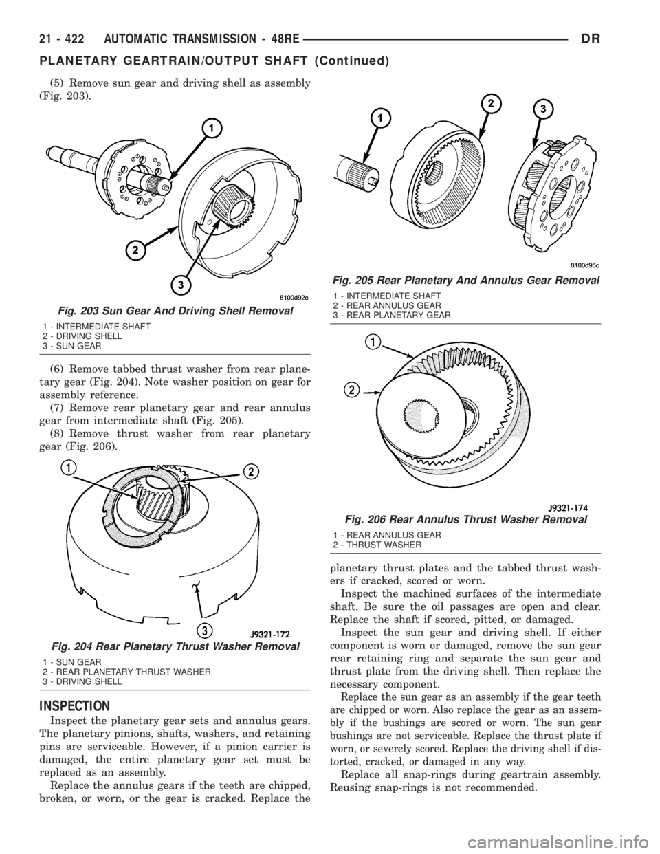
(5) Remove sun gear and driving shell as assembly
(Fig. 203).
(6) Remove tabbed thrust washer from rear plane-
tary gear (Fig. 204). Note washer position on gear for
assembly reference.
(7) Remove rear planetary gear and rear annulus
gear from intermediate shaft (Fig. 205).
(8) Remove thrust washer from rear planetary
gear (Fig. 206).
INSPECTION
Inspect the planetary gear sets and annulus gears.
The planetary pinions, shafts, washers, and retaining
pins are serviceable. However, if a pinion carrier is
damaged, the entire planetary gear set must be
replaced as an assembly.
Replace the annulus gears if the teeth are chipped,
broken, or worn, or the gear is cracked. Replace theplanetary thrust plates and the tabbed thrust wash-
ers if cracked, scored or worn.
Inspect the machined surfaces of the intermediate
shaft. Be sure the oil passages are open and clear.
Replace the shaft if scored, pitted, or damaged.
Inspect the sun gear and driving shell. If either
component is worn or damaged, remove the sun gear
rear retaining ring and separate the sun gear and
thrust plate from the driving shell. Then replace the
necessary component.
Replace the sun gear as an assembly if the gear teeth
are chipped or worn. Also replace the gear as an assem-
bly if the bushings are scored or worn. The sun gear
bushings are not serviceable. Replace the thrust plate if
worn, or severely scored. Replace the driving shell if dis-
torted, cracked, or damaged in any way.
Replace all snap-rings during geartrain assembly.
Reusing snap-rings is not recommended.
Fig. 203 Sun Gear And Driving Shell Removal
1 - INTERMEDIATE SHAFT
2 - DRIVING SHELL
3 - SUN GEAR
Fig. 204 Rear Planetary Thrust Washer Removal
1 - SUN GEAR
2 - REAR PLANETARY THRUST WASHER
3 - DRIVING SHELL
Fig. 205 Rear Planetary And Annulus Gear Removal
1 - INTERMEDIATE SHAFT
2 - REAR ANNULUS GEAR
3 - REAR PLANETARY GEAR
Fig. 206 Rear Annulus Thrust Washer Removal
1 - REAR ANNULUS GEAR
2 - THRUST WASHER
21 - 422 AUTOMATIC TRANSMISSION - 48REDR
PLANETARY GEARTRAIN/OUTPUT SHAFT (Continued)
Page 2262 of 2895
ASSEMBLY
(1) Lubricate sun gear and planetary gears with
transmission fluid during assembly. Use petroleum
jelly to lubricate intermediate shaft bushing surfaces,
thrust washers and thrust plates and to hold these
parts in place during assembly.
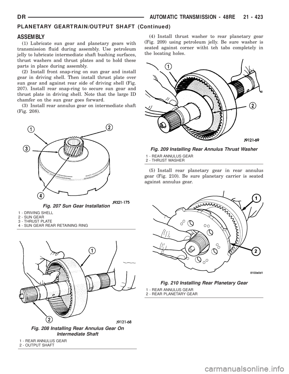
(2) Install front snap-ring on sun gear and install
gear in driving shell. Then install thrust plate over
sun gear and against rear side of driving shell (Fig.
207). Install rear snap-ring to secure sun gear and
thrust plate in driving shell. Note that the large ID
chamfer on the sun gear goes forward.
(3) Install rear annulus gear on intermediate shaft
(Fig. 208).(4) Install thrust washer to rear planetary gear
(Fig. 209) using petroleum jelly. Be sure washer is
seated against corner witht teh tabs completely in
the locating holes.
(5) Install rear planetary gear in rear annulus
gear (Fig. 210). Be sure planetary carrier is seated
against annulus gear.
Fig. 207 Sun Gear Installation
1 - DRIVING SHELL
2 - SUN GEAR
3 - THRUST PLATE
4 - SUN GEAR REAR RETAINING RING
Fig. 208 Installing Rear Annulus Gear On
Intermediate Shaft
1 - REAR ANNULUS GEAR
2 - OUTPUT SHAFT
Fig. 210 Installing Rear Planetary Gear
1 - REAR ANNULUS GEAR
2 - REAR PLANETARY GEAR
Fig. 209 Installing Rear Annulus Thrust Washer
1 - REAR ANNULUS GEAR
2 - THRUST WASHER
DRAUTOMATIC TRANSMISSION - 48RE 21 - 423
PLANETARY GEARTRAIN/OUTPUT SHAFT (Continued)
Page 2263 of 2895
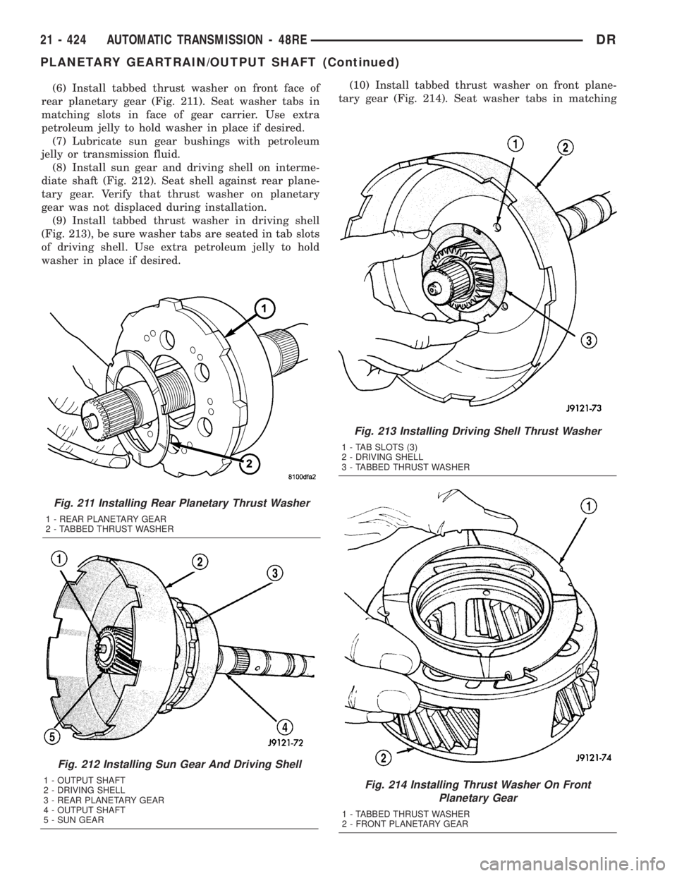
(6) Install tabbed thrust washer on front face of
rear planetary gear (Fig. 211). Seat washer tabs in
matching slots in face of gear carrier. Use extra
petroleum jelly to hold washer in place if desired.
(7) Lubricate sun gear bushings with petroleum
jelly or transmission fluid.
(8) Install sun gear and driving shell on interme-
diate shaft (Fig. 212). Seat shell against rear plane-
tary gear. Verify that thrust washer on planetary
gear was not displaced during installation.
(9) Install tabbed thrust washer in driving shell
(Fig. 213), be sure washer tabs are seated in tab slots
of driving shell. Use extra petroleum jelly to hold
washer in place if desired.(10) Install tabbed thrust washer on front plane-
tary gear (Fig. 214). Seat washer tabs in matching
Fig. 211 Installing Rear Planetary Thrust Washer
1 - REAR PLANETARY GEAR
2 - TABBED THRUST WASHER
Fig. 212 Installing Sun Gear And Driving Shell
1 - OUTPUT SHAFT
2 - DRIVING SHELL
3 - REAR PLANETARY GEAR
4 - OUTPUT SHAFT
5 - SUN GEAR
Fig. 213 Installing Driving Shell Thrust Washer
1 - TAB SLOTS (3)
2 - DRIVING SHELL
3 - TABBED THRUST WASHER
Fig. 214 Installing Thrust Washer On Front
Planetary Gear
1 - TABBED THRUST WASHER
2 - FRONT PLANETARY GEAR
21 - 424 AUTOMATIC TRANSMISSION - 48REDR
PLANETARY GEARTRAIN/OUTPUT SHAFT (Continued)
Page 2264 of 2895
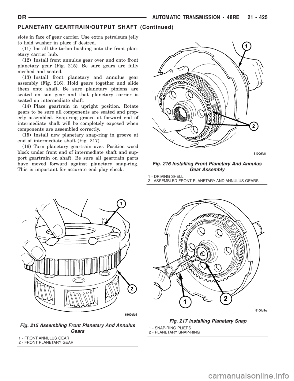
slots in face of gear carrier. Use extra petroleum jelly
to hold washer in place if desired.
(11) Install the torlon bushing onto the front plan-
etary carrier hub.
(12) Install front annulus gear over and onto front
planetary gear (Fig. 215). Be sure gears are fully
meshed and seated.
(13) Install front planetary and annulus gear
assembly (Fig. 216). Hold gears together and slide
them onto shaft. Be sure planetary pinions are
seated on sun gear and that planetary carrier is
seated on intermediate shaft.
(14) Place geartrain in upright position. Rotate
gears to be sure all components are seated and prop-
erly assembled. Snap-ring groove at forward end of
intermediate shaft will be completely exposed when
components are assembled correctly.
(15) Install new planetary snap-ring in groove at
end of intermediate shaft (Fig. 217).
(16) Turn planetary geartrain over. Position wood
block under front end of intermediate shaft and sup-
port geartrain on shaft. Be sure all geartrain parts
have moved forward against planetary snap-ring.
This is important for accurate end play check.
Fig. 215 Assembling Front Planetary And Annulus
Gears
1 - FRONT ANNULUS GEAR
2 - FRONT PLANETARY GEAR
Fig. 216 Installing Front Planetary And Annulus
Gear Assembly
1 - DRIVING SHELL
2 - ASSEMBLED FRONT PLANETARY AND ANNULUS GEARS
Fig. 217 Installing Planetary Snap
1 - SNAP-RING PLIERS
2 - PLANETARY SNAP-RING
DRAUTOMATIC TRANSMISSION - 48RE 21 - 425
PLANETARY GEARTRAIN/OUTPUT SHAFT (Continued)
Page 2267 of 2895
CLEANING
Clean the clutch components with solvent and dry
them with compressed air. Do not use rags or shop
towels to dry any of the clutch parts. Lint from such
materials will adhere to component surfaces and
could restrict or block fluid passages after assembly.
INSPECTION
Replace the clutch discs if warped, worn, scored,
burned/charred, the lugs are damaged, or if the fac-
ing is flaking off. Replace the top and bottom pres-
sure plates if scored, warped, or cracked. Be sure the
driving lugs on the pressure and clutch plates are
also in good condition. The lugs must not be bent,
cracked or damaged in any way.
Replace the piston spring and wave spring if either
part is distorted, warped or broken.
Check the lug grooves in the clutch retainer. The
clutch and pressure plates should slide freely in the
slots. Replace the retainer if the grooves are worn or
damaged. Also check action of the check balls in the
retainer and piston. Each check ball must move
freely and not stick.
Replace the retainer bushing if worn, scored, or
doubt exists about bushing condition.
Inspect the piston and retainer seal surfaces for
nicks or scratches. Minor scratches can be removed
with crocus cloth. However, replace the piston and/or
retainer if the seal surfaces are seriously scored.
Check condition of the fiber thrust washer and
metal output shaft thrust washer. Replace either
washer if worn or damaged.
Check condition of the seal rings on the input shaft
and clutch retainer hub. Replace the seal rings only
if worn, distorted, or damaged. The input shaft front
seal ring is teflon with chamfered ends. The rear ring
is metal with interlocking ends.
Check the input shaft for wear, or damage. Replace
the shaft if worn, scored or damaged in any way.
ASSEMBLY
(1) Soak clutch discs in transmission fluid while
assembling other clutch parts.
(2) Install new seal rings on clutch retainer hub
and input shaft if necessary.
(a) Be sure clutch hub seal ring is fully seated in
groove and is not twisted.
(3) Lubricate splined end of input shaft and clutch
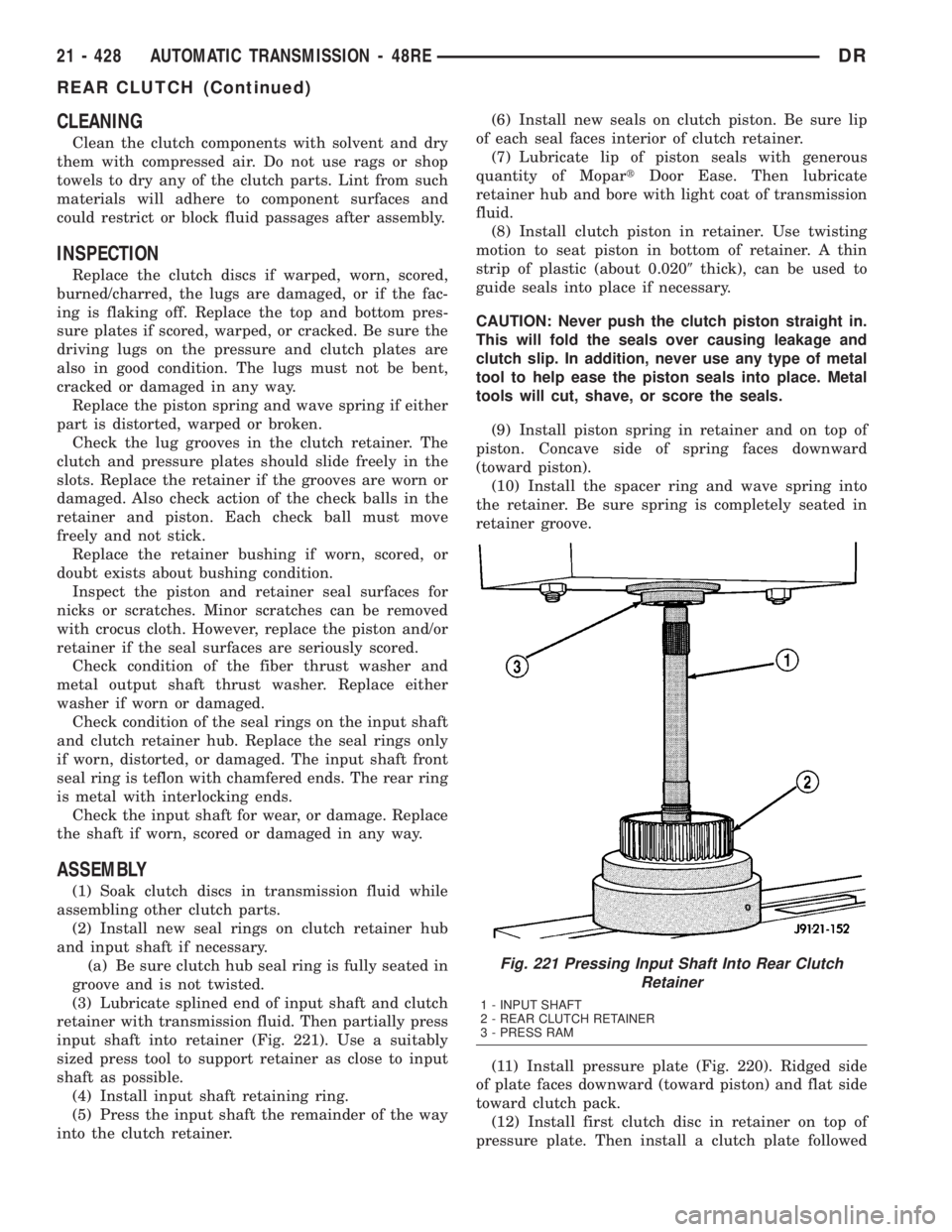
retainer with transmission fluid. Then partially press
input shaft into retainer (Fig. 221). Use a suitably
sized press tool to support retainer as close to input
shaft as possible.
(4) Install input shaft retaining ring.
(5) Press the input shaft the remainder of the way
into the clutch retainer.(6) Install new seals on clutch piston. Be sure lip
of each seal faces interior of clutch retainer.
(7) Lubricate lip of piston seals with generous
quantity of MopartDoor Ease. Then lubricate
retainer hub and bore with light coat of transmission
fluid.
(8) Install clutch piston in retainer. Use twisting
motion to seat piston in bottom of retainer. A thin
strip of plastic (about 0.0209thick), can be used to
guide seals into place if necessary.
CAUTION: Never push the clutch piston straight in.
This will fold the seals over causing leakage and
clutch slip. In addition, never use any type of metal
tool to help ease the piston seals into place. Metal
tools will cut, shave, or score the seals.
(9) Install piston spring in retainer and on top of
piston. Concave side of spring faces downward
(toward piston).
(10) Install the spacer ring and wave spring into
the retainer. Be sure spring is completely seated in
retainer groove.
(11) Install pressure plate (Fig. 220). Ridged side
of plate faces downward (toward piston) and flat side
toward clutch pack.
(12) Install first clutch disc in retainer on top of
pressure plate. Then install a clutch plate followed
Fig. 221 Pressing Input Shaft Into Rear Clutch
Retainer
1 - INPUT SHAFT
2 - REAR CLUTCH RETAINER
3 - PRESS RAM
21 - 428 AUTOMATIC TRANSMISSION - 48REDR
REAR CLUTCH (Continued)
Page 2278 of 2895
STATOR
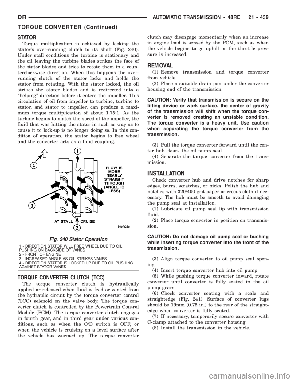
Torque multiplication is achieved by locking the
stator's over-running clutch to its shaft (Fig. 240).
Under stall conditions the turbine is stationary and
the oil leaving the turbine blades strikes the face of
the stator blades and tries to rotate them in a coun-
terclockwise direction. When this happens the over-
running clutch of the stator locks and holds the
stator from rotating. With the stator locked, the oil
strikes the stator blades and is redirected into a
ªhelpingº direction before it enters the impeller. This
circulation of oil from impeller to turbine, turbine to
stator, and stator to impeller, can produce a maxi-
mum torque multiplication of about 1.75:1. As the
turbine begins to match the speed of the impeller, the
fluid that was hitting the stator in such as way as to
cause it to lock-up is no longer doing so. In this con-
dition of operation, the stator begins to free wheel
and the converter acts as a fluid coupling.
TORQUE CONVERTER CLUTCH (TCC)
The torque converter clutch is hydraulically
applied or released when fluid is feed or vented from
the hydraulic circuit by the torque converter control
(TCC) solenoid on the valve body. The torque con-
verter clutch is controlled by the Powertrain Control
Module (PCM). The torque converter clutch engages
in fourth gear, and in third gear under various con-
ditions, such as when the O/D switch is OFF, or
when the vehicle is cruising on a level surface after
the vehicle has warmed up. The torque converterclutch may disengage momentarily when an increase
in engine load is sensed by the PCM, such as when
the vehicle begins to go uphill or the throttle pres-
sure is increased.
REMOVAL
(1) Remove transmission and torque converter
from vehicle.
(2) Place a suitable drain pan under the converter
housing end of the transmission.
CAUTION: Verify that transmission is secure on the
lifting device or work surface, the center of gravity
of the transmission will shift when the torque con-
verter is removed creating an unstable condition.
The torque converter is a heavy unit. Use caution
when separating the torque converter from the
transmission.
(3) Pull the torque converter forward until the cen-
ter hub clears the oil pump seal.
(4) Separate the torque converter from the trans-
mission.
INSTALLATION
Check converter hub and drive notches for sharp
edges, burrs, scratches, or nicks. Polish the hub and
notches with 320/400 grit paper or crocus cloth if nec-
essary. The hub must be smooth to avoid damaging
the pump seal at installation.
(1) Lubricate oil pump seal lip with transmission
fluid.
(2) Place torque converter in position on transmis-
sion.
CAUTION: Do not damage oil pump seal or bushing
while inserting torque converter into the front of the
transmission.
(3) Align torque converter to oil pump seal open-
ing.
(4) Insert torque converter hub into oil pump.
(5) While pushing torque converter inward, rotate
converter until converter is fully seated in the oil
pump gears.
(6) Check converter seating with a scale and
straightedge (Fig. 241). Surface of converter lugs
should be 19mm (0.75 in.) to the rear of the straight-
edge when converter is fully seated.
(7) If necessary, temporarily secure converter with
C-clamp attached to the converter housing.
(8) Install the transmission in the vehicle.
Fig. 240 Stator Operation
1 - DIRECTION STATOR WILL FREE WHEEL DUE TO OIL
PUSHING ON BACKSIDE OF VANES
2 - FRONT OF ENGINE
3 - INCREASED ANGLE AS OIL STRIKES VANES
4 - DIRECTION STATOR IS LOCKED UP DUE TO OIL PUSHING
AGAINST STATOR VANES
DRAUTOMATIC TRANSMISSION - 48RE 21 - 439
TORQUE CONVERTER (Continued)
Page 2405 of 2895
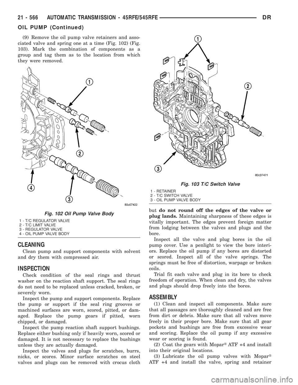
(9) Remove the oil pump valve retainers and asso-
ciated valve and spring one at a time (Fig. 102) (Fig.
103). Mark the combination of components as a
group and tag them as to the location from which
they were removed.
CLEANING
Clean pump and support components with solvent
and dry them with compressed air.
INSPECTION
Check condition of the seal rings and thrust
washer on the reaction shaft support. The seal rings
do not need to be replaced unless cracked, broken, or
severely worn.
Inspect the pump and support components. Replace
the pump or support if the seal ring grooves or
machined surfaces are worn, scored, pitted, or dam-
aged. Replace the pump gears if pitted, worn
chipped, or damaged.
Inspect the pump reaction shaft support bushings.
Replace either bushing only if heavily worn, scored or
damaged. It is not necessary to replace the bushings
unless they are actually damaged.
Inspect the valves and plugs for scratches, burrs,
nicks, or scores. Minor surface scratches on steel
valves and plugs can be removed with crocus clothbutdo not round off the edges of the valve or
plug lands.Maintaining sharpness of these edges is
vitally important. The edges prevent foreign matter
from lodging between the valves and plugs and the
bore.
Inspect all the valve and plug bores in the oil
pump cover. Use a penlight to view the bore interi-
ors. Replace the oil pump if any bores are distorted
or scored. Inspect all of the valve springs. The
springs must be free of distortion, warpage or broken
coils.
Trial fit each valve and plug in its bore to check
freedom of operation. When clean and dry, the valves
and plugs should drop freely into the bores.
ASSEMBLY
(1) Clean and inspect all components. Make sure
that all passages are thoroughly cleaned and are free
from dirt or debris. Make sure that all valves move
freely in their proper bore. Make sure that all gear
pockets and bushings are free from excessive wear
and scoring. Replace the oil pump if any excessive
wear or scoring is found.
(2) Coat the gears with MopartATF +4 and install
into their original locations.
(3) Lubricate the oil pump valves with Mopart
ATF +4 and install the valve, spring and retainer
Fig. 102 Oil Pump Valve Body
1 - T/C REGULATOR VALVE
2 - T/C LIMIT VALVE
3 - REGULATOR VALVE
4 - OIL PUMP VALVE BODY
Fig. 103 T/C Switch Valve
1 - RETAINER
2 - T/C SWITCH VALVE
3 - OIL PUMP VALVE BODY
21 - 566 AUTOMATIC TRANSMISSION - 45RFE/545RFEDR
OIL PUMP (Continued)
Page 2412 of 2895
DISASSEMBLY
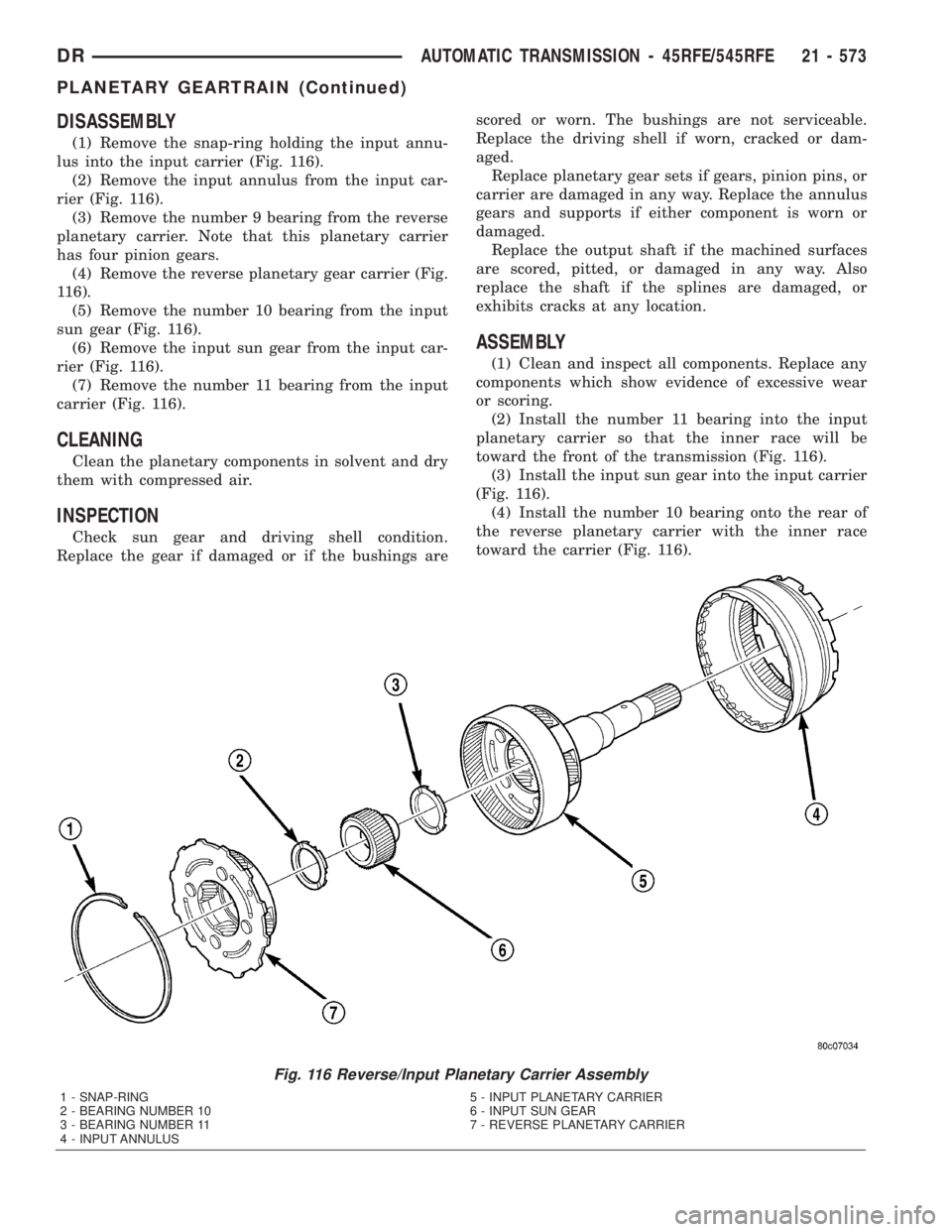
(1) Remove the snap-ring holding the input annu-
lus into the input carrier (Fig. 116).
(2) Remove the input annulus from the input car-
rier (Fig. 116).
(3) Remove the number 9 bearing from the reverse
planetary carrier. Note that this planetary carrier
has four pinion gears.
(4) Remove the reverse planetary gear carrier (Fig.
116).
(5) Remove the number 10 bearing from the input
sun gear (Fig. 116).
(6) Remove the input sun gear from the input car-
rier (Fig. 116).
(7) Remove the number 11 bearing from the input
carrier (Fig. 116).
CLEANING
Clean the planetary components in solvent and dry
them with compressed air.
INSPECTION
Check sun gear and driving shell condition.
Replace the gear if damaged or if the bushings arescored or worn. The bushings are not serviceable.
Replace the driving shell if worn, cracked or dam-
aged.
Replace planetary gear sets if gears, pinion pins, or
carrier are damaged in any way. Replace the annulus
gears and supports if either component is worn or
damaged.
Replace the output shaft if the machined surfaces
are scored, pitted, or damaged in any way. Also
replace the shaft if the splines are damaged, or
exhibits cracks at any location.
ASSEMBLY
(1) Clean and inspect all components. Replace any
components which show evidence of excessive wear
or scoring.
(2) Install the number 11 bearing into the input
planetary carrier so that the inner race will be
toward the front of the transmission (Fig. 116).
(3) Install the input sun gear into the input carrier
(Fig. 116).
(4) Install the number 10 bearing onto the rear of
the reverse planetary carrier with the inner race
toward the carrier (Fig. 116).
Fig. 116 Reverse/Input Planetary Carrier Assembly
1 - SNAP-RING 5 - INPUT PLANETARY CARRIER
2 - BEARING NUMBER 10 6 - INPUT SUN GEAR
3 - BEARING NUMBER 11 7 - REVERSE PLANETARY CARRIER
4 - INPUT ANNULUS
DRAUTOMATIC TRANSMISSION - 45RFE/545RFE 21 - 573
PLANETARY GEARTRAIN (Continued)
Page 2430 of 2895
TRANSFER CASE - NV241 GENII
TABLE OF CONTENTS
page page
TRANSFER CASE - NV241 GENII
DESCRIPTION........................591
OPERATION..........................591
DIAGNOSIS AND TESTING - TRANSFER
CASE - NV241 GENII..................592
REMOVAL............................593
DISASSEMBLY........................593
CLEANING...........................602
INSPECTION.........................602
ASSEMBLY...........................604
INSTALLATION........................614
SPECIFICATIONS
TRANSFER CASE - NV241 GENII........614
SPECIAL TOOLS
TRANSFER CASE - NV241/NV243........615
EXTENSION HOUSING BUSHING AND SEAL
REMOVAL............................616INSTALLATION........................616
FLUID
STANDARD PROCEDURE - FLUID DRAIN AND
REFILL............................617
FRONT OUTPUT SHAFT SEAL
REMOVAL............................617
INSTALLATION........................618
POSITION SENSOR
DESCRIPTION........................618
OPERATION..........................619
REMOVAL............................619
INSTALLATION........................619
SHIFT LEVER
REMOVAL............................620
INSTALLATION........................621
ADJUSTMENTS
ADJUSTMENT - SHIFT LEVER..........622
TRANSFER CASE - NV241
GENII
DESCRIPTION
The NV241 GENII transfer case is a part-time
transfer case with a low-range gear system. It pro-
vides three operating ranges plus a NEUTRAL posi-
tion. The low range position provides a gear
reduction ratio of 2.72:1 for increased low speed
torque capability.
The gear cases and extension are all of aluminum
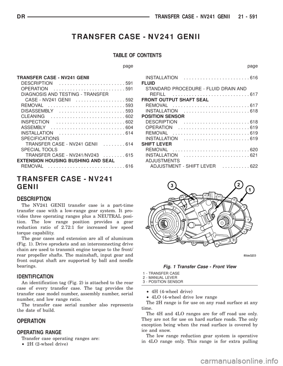
(Fig. 1). Drive sprockets and an interconnecting drive
chain are used to transmit engine torque to the front/
rear propeller shafts. The mainshaft, input gear and
front output shaft are supported by ball and needle
bearings.
IDENTIFICATION
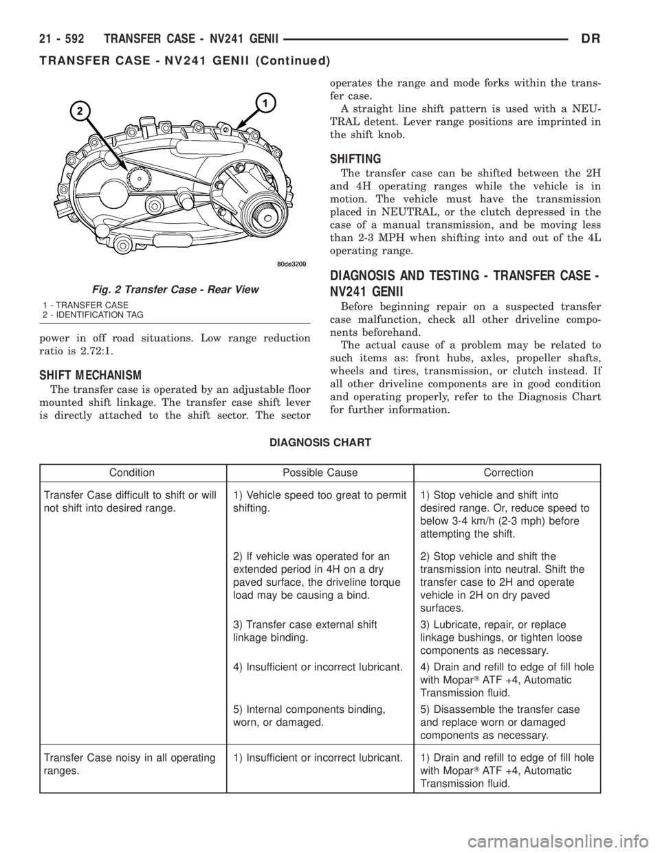
An identification tag (Fig. 2) is attached to the rear
case of every transfer case. The tag provides the
transfer case model number, assembly number, serial
number, and low range ratio.
The transfer case serial number also represents
the date of build.
OPERATION
OPERATING RANGE
Transfer case operating ranges are:
²2H (2-wheel drive)²4H (4-wheel drive)
²4LO (4-wheel drive low range
The 2H range is for use on any road surface at any
time.
The 4H and 4LO ranges are for off road use only.
They are not for use on hard surface roads. The only
exception being when the road surface is covered by
ice and snow.
The low range reduction gear system is operative
in 4LO range only. This range is for extra pulling
Fig. 1 Transfer Case - Front View
1 - TRANSFER CASE
2 - MANUAL LEVER
3 - POSITION SENSOR
DRTRANSFER CASE - NV241 GENII 21 - 591
Page 2431 of 2895
power in off road situations. Low range reduction
ratio is 2.72:1.
SHIFT MECHANISM
The transfer case is operated by an adjustable floor
mounted shift linkage. The transfer case shift lever
is directly attached to the shift sector. The sectoroperates the range and mode forks within the trans-
fer case.
A straight line shift pattern is used with a NEU-
TRAL detent. Lever range positions are imprinted in
the shift knob.
SHIFTING
The transfer case can be shifted between the 2H
and 4H operating ranges while the vehicle is in
motion. The vehicle must have the transmission
placed in NEUTRAL, or the clutch depressed in the
case of a manual transmission, and be moving less
than 2-3 MPH when shifting into and out of the 4L
operating range.
DIAGNOSIS AND TESTING - TRANSFER CASE -
NV241 GENII
Before beginning repair on a suspected transfer
case malfunction, check all other driveline compo-
nents beforehand.
The actual cause of a problem may be related to
such items as: front hubs, axles, propeller shafts,
wheels and tires, transmission, or clutch instead. If
all other driveline components are in good condition
and operating properly, refer to the Diagnosis Chart
for further information.
DIAGNOSIS CHART
Condition Possible Cause Correction
Transfer Case difficult to shift or will
not shift into desired range.1) Vehicle speed too great to permit
shifting.1) Stop vehicle and shift into
desired range. Or, reduce speed to
below 3-4 km/h (2-3 mph) before
attempting the shift.
2) If vehicle was operated for an
extended period in 4H on a dry
paved surface, the driveline torque
load may be causing a bind.2) Stop vehicle and shift the
transmission into neutral. Shift the
transfer case to 2H and operate
vehicle in 2H on dry paved
surfaces.
3) Transfer case external shift
linkage binding.3) Lubricate, repair, or replace
linkage bushings, or tighten loose
components as necessary.
4) Insufficient or incorrect lubricant. 4) Drain and refill to edge of fill hole
with MoparTATF +4, Automatic
Transmission fluid.
5) Internal components binding,
worn, or damaged.5) Disassemble the transfer case
and replace worn or damaged
components as necessary.
Transfer Case noisy in all operating
ranges.1) Insufficient or incorrect lubricant. 1) Drain and refill to edge of fill hole
with MoparTATF +4, Automatic
Transmission fluid.
Fig. 2 Transfer Case - Rear View
1 - TRANSFER CASE
2 - IDENTIFICATION TAG
21 - 592 TRANSFER CASE - NV241 GENIIDR
TRANSFER CASE - NV241 GENII (Continued)