bushing DODGE RAM 2003 Service Owners Manual
[x] Cancel search | Manufacturer: DODGE, Model Year: 2003, Model line: RAM, Model: DODGE RAM 2003Pages: 2895, PDF Size: 83.15 MB
Page 2066 of 2895
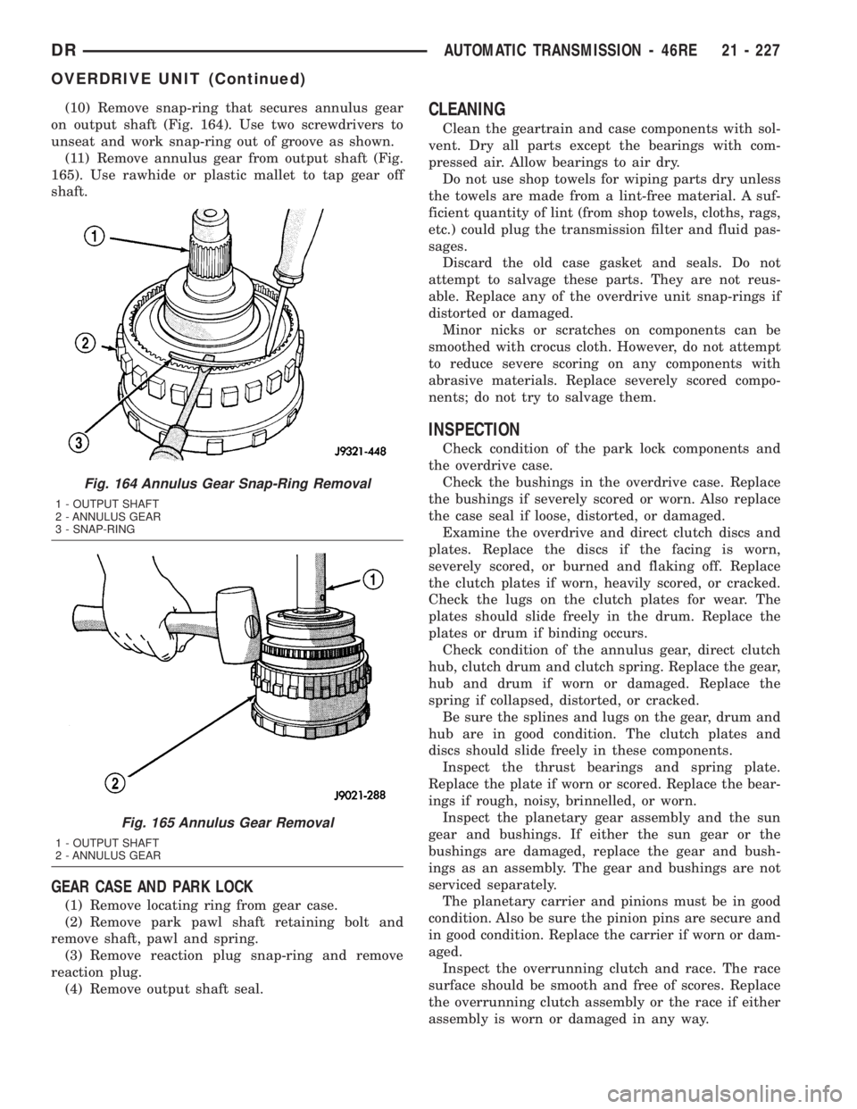
(10) Remove snap-ring that secures annulus gear
on output shaft (Fig. 164). Use two screwdrivers to
unseat and work snap-ring out of groove as shown.
(11) Remove annulus gear from output shaft (Fig.
165). Use rawhide or plastic mallet to tap gear off
shaft.
GEAR CASE AND PARK LOCK
(1) Remove locating ring from gear case.
(2) Remove park pawl shaft retaining bolt and
remove shaft, pawl and spring.
(3) Remove reaction plug snap-ring and remove
reaction plug.
(4) Remove output shaft seal.
CLEANING
Clean the geartrain and case components with sol-
vent. Dry all parts except the bearings with com-
pressed air. Allow bearings to air dry.
Do not use shop towels for wiping parts dry unless
the towels are made from a lint-free material. A suf-
ficient quantity of lint (from shop towels, cloths, rags,
etc.) could plug the transmission filter and fluid pas-
sages.
Discard the old case gasket and seals. Do not
attempt to salvage these parts. They are not reus-
able. Replace any of the overdrive unit snap-rings if
distorted or damaged.
Minor nicks or scratches on components can be
smoothed with crocus cloth. However, do not attempt
to reduce severe scoring on any components with
abrasive materials. Replace severely scored compo-
nents; do not try to salvage them.
INSPECTION
Check condition of the park lock components and
the overdrive case.
Check the bushings in the overdrive case. Replace
the bushings if severely scored or worn. Also replace
the case seal if loose, distorted, or damaged.
Examine the overdrive and direct clutch discs and
plates. Replace the discs if the facing is worn,
severely scored, or burned and flaking off. Replace
the clutch plates if worn, heavily scored, or cracked.
Check the lugs on the clutch plates for wear. The
plates should slide freely in the drum. Replace the
plates or drum if binding occurs.
Check condition of the annulus gear, direct clutch
hub, clutch drum and clutch spring. Replace the gear,
hub and drum if worn or damaged. Replace the
spring if collapsed, distorted, or cracked.
Be sure the splines and lugs on the gear, drum and
hub are in good condition. The clutch plates and
discs should slide freely in these components.
Inspect the thrust bearings and spring plate.
Replace the plate if worn or scored. Replace the bear-
ings if rough, noisy, brinnelled, or worn.
Inspect the planetary gear assembly and the sun
gear and bushings. If either the sun gear or the
bushings are damaged, replace the gear and bush-
ings as an assembly. The gear and bushings are not
serviced separately.
The planetary carrier and pinions must be in good
condition. Also be sure the pinion pins are secure and
in good condition. Replace the carrier if worn or dam-
aged.
Inspect the overrunning clutch and race. The race
surface should be smooth and free of scores. Replace
the overrunning clutch assembly or the race if either
assembly is worn or damaged in any way.
Fig. 164 Annulus Gear Snap-Ring Removal
1 - OUTPUT SHAFT
2 - ANNULUS GEAR
3 - SNAP-RING
Fig. 165 Annulus Gear Removal
1 - OUTPUT SHAFT
2 - ANNULUS GEAR
DRAUTOMATIC TRANSMISSION - 46RE 21 - 227
OVERDRIVE UNIT (Continued)
Page 2067 of 2895
Replace the shaft pilot bushing and inner bushing
if damaged. Replace either shaft bearing if rough or
noisy. Replace the bearing snap-rings if distorted or
cracked.
Check the machined surfaces on the output shaft.
These surfaces should clean and smooth. Very minor
nicks or scratches can be smoothed with crocus cloth.
Replace the shaft if worn, scored or damaged in any
way.
Inspect the output shaft bushings. The small bush-
ing is the intermediate shaft pilot bushing. The large
bushing is the overrunning clutch hub bushing.
Replace either bushing if scored, pitted, cracked, or
worn.
ASSEMBLY
GEARTRAIN AND DIRECT CLUTCH
(1) Soak direct clutch and overdrive clutch discs in
MopartATF +4, Automatic Transmission fluid. Allow
discs to soak for 10-20 minutes.
(2) Install new pilot bushing and clutch hub bush-
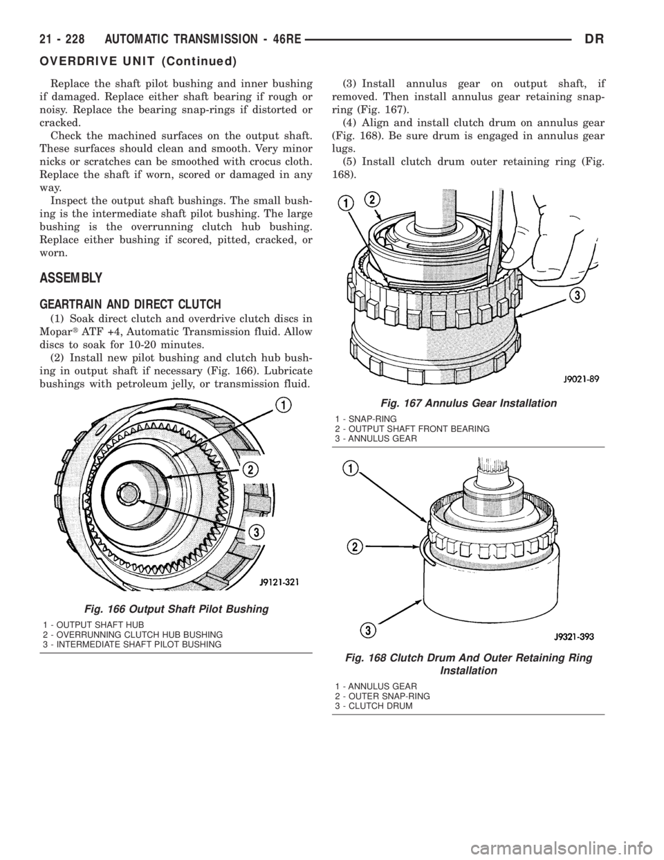
ing in output shaft if necessary (Fig. 166). Lubricate
bushings with petroleum jelly, or transmission fluid.(3) Install annulus gear on output shaft, if
removed. Then install annulus gear retaining snap-
ring (Fig. 167).
(4) Align and install clutch drum on annulus gear
(Fig. 168). Be sure drum is engaged in annulus gear
lugs.
(5) Install clutch drum outer retaining ring (Fig.
168).
Fig. 166 Output Shaft Pilot Bushing
1 - OUTPUT SHAFT HUB
2 - OVERRUNNING CLUTCH HUB BUSHING
3 - INTERMEDIATE SHAFT PILOT BUSHING
Fig. 167 Annulus Gear Installation
1 - SNAP-RING
2 - OUTPUT SHAFT FRONT BEARING
3 - ANNULUS GEAR
Fig. 168 Clutch Drum And Outer Retaining Ring
Installation
1 - ANNULUS GEAR
2 - OUTER SNAP-RING
3 - CLUTCH DRUM
21 - 228 AUTOMATIC TRANSMISSION - 46REDR
OVERDRIVE UNIT (Continued)
Page 2074 of 2895
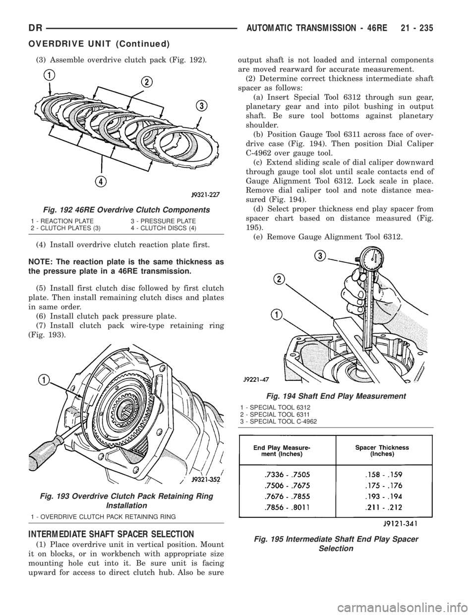
(3) Assemble overdrive clutch pack (Fig. 192).
(4) Install overdrive clutch reaction plate first.
NOTE: The reaction plate is the same thickness as
the pressure plate in a 46RE transmission.
(5) Install first clutch disc followed by first clutch
plate. Then install remaining clutch discs and plates
in same order.
(6) Install clutch pack pressure plate.
(7) Install clutch pack wire-type retaining ring
(Fig. 193).
INTERMEDIATE SHAFT SPACER SELECTION
(1) Place overdrive unit in vertical position. Mount
it on blocks, or in workbench with appropriate size
mounting hole cut into it. Be sure unit is facing
upward for access to direct clutch hub. Also be sureoutput shaft is not loaded and internal components
are moved rearward for accurate measurement.
(2) Determine correct thickness intermediate shaft
spacer as follows:
(a) Insert Special Tool 6312 through sun gear,
planetary gear and into pilot bushing in output
shaft. Be sure tool bottoms against planetary
shoulder.
(b) Position Gauge Tool 6311 across face of over-
drive case (Fig. 194). Then position Dial Caliper
C-4962 over gauge tool.
(c) Extend sliding scale of dial caliper downward
through gauge tool slot until scale contacts end of
Gauge Alignment Tool 6312. Lock scale in place.
Remove dial caliper tool and note distance mea-
sured (Fig. 194).
(d) Select proper thickness end play spacer from
spacer chart based on distance measured (Fig.
195).
(e) Remove Gauge Alignment Tool 6312.
Fig. 192 46RE Overdrive Clutch Components
1 - REACTION PLATE 3 - PRESSURE PLATE
2 - CLUTCH PLATES (3) 4 - CLUTCH DISCS (4)
Fig. 193 Overdrive Clutch Pack Retaining Ring
Installation
1 - OVERDRIVE CLUTCH PACK RETAINING RING
Fig. 194 Shaft End Play Measurement
1 - SPECIAL TOOL 6312
2 - SPECIAL TOOL 6311
3 - SPECIAL TOOL C-4962
Fig. 195 Intermediate Shaft End Play Spacer
Selection
DRAUTOMATIC TRANSMISSION - 46RE 21 - 235
OVERDRIVE UNIT (Continued)
Page 2084 of 2895
INSPECTION
Inspect the planetary gear sets and annulus gears.
The planetary pinions, shafts, washers, and retaining
pins are serviceable. However, if a pinion carrier is
damaged, the entire planetary gear set must be
replaced as an assembly.
Replace the annulus gears if the teeth are chipped,
broken, or worn, or the gear is cracked. Replace the
planetary thrust plates and the tabbed thrust wash-
ers if cracked, scored or worn.
Inspect the machined surfaces of the intermediate
shaft. Be sure the oil passages are open and clear.
Replace the shaft if scored, pitted, or damaged.
Inspect the sun gear and driving shell. If either
component is worn or damaged, remove the sun gear
rear retaining ring and separate the sun gear and
thrust plate from the driving shell. Then replace the
necessary component.
Replace the sun gear as an assembly if the gear
teeth are chipped or worn. Also replace the gear as
an assembly if the bushings are scored or worn. The
sun gear bushings are not serviceable. Replace the
thrust plate if worn, or severely scored. Replace the
driving shell if distorted, cracked, or damaged in any
way.
Replace all snap-rings during geartrain assembly.
Reusing snap-rings is not recommended.
ASSEMBLY
(1) Lubricate sun gear and planetary gears with
transmission fluid during assembly. Use petroleum
jelly to lubricate intermediate shaft bushing surfaces,
thrust washers and thrust plates and to hold these
parts in place during assembly.
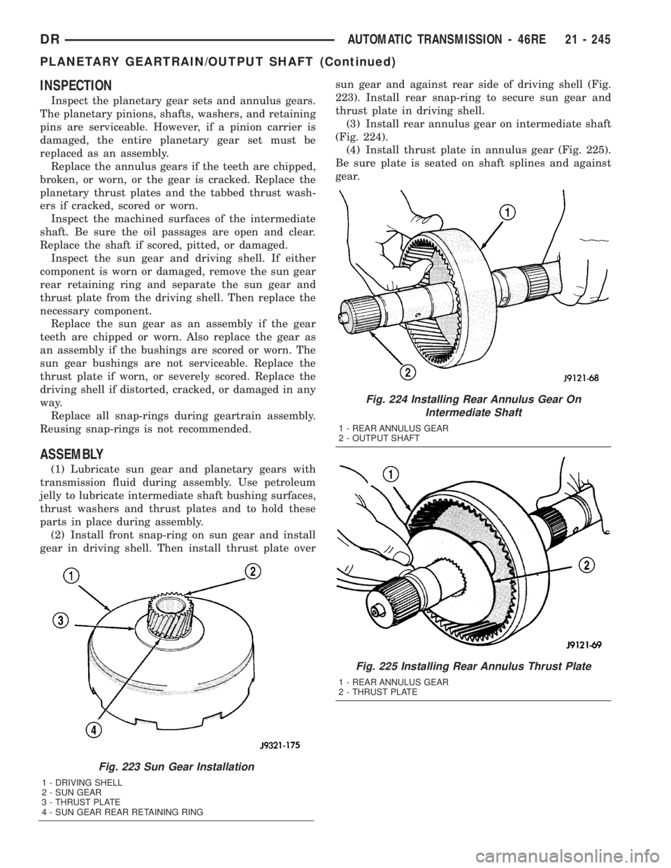
(2) Install front snap-ring on sun gear and install
gear in driving shell. Then install thrust plate oversun gear and against rear side of driving shell (Fig.
223). Install rear snap-ring to secure sun gear and
thrust plate in driving shell.
(3) Install rear annulus gear on intermediate shaft
(Fig. 224).
(4) Install thrust plate in annulus gear (Fig. 225).
Be sure plate is seated on shaft splines and against
gear.
Fig. 223 Sun Gear Installation
1 - DRIVING SHELL
2 - SUN GEAR
3 - THRUST PLATE
4 - SUN GEAR REAR RETAINING RING
Fig. 224 Installing Rear Annulus Gear On
Intermediate Shaft
1 - REAR ANNULUS GEAR
2 - OUTPUT SHAFT
Fig. 225 Installing Rear Annulus Thrust Plate
1 - REAR ANNULUS GEAR
2 - THRUST PLATE
DRAUTOMATIC TRANSMISSION - 46RE 21 - 245
PLANETARY GEARTRAIN/OUTPUT SHAFT (Continued)
Page 2085 of 2895
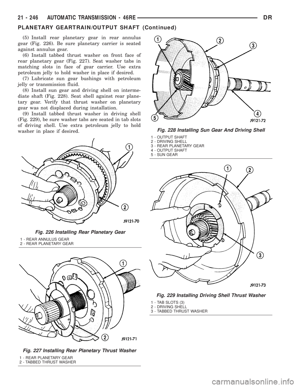
(5) Install rear planetary gear in rear annulus
gear (Fig. 226). Be sure planetary carrier is seated
against annulus gear.
(6) Install tabbed thrust washer on front face of
rear planetary gear (Fig. 227). Seat washer tabs in
matching slots in face of gear carrier. Use extra
petroleum jelly to hold washer in place if desired.
(7) Lubricate sun gear bushings with petroleum
jelly or transmission fluid.
(8) Install sun gear and driving shell on interme-
diate shaft (Fig. 228). Seat shell against rear plane-
tary gear. Verify that thrust washer on planetary
gear was not displaced during installation.
(9) Install tabbed thrust washer in driving shell
(Fig. 229), be sure washer tabs are seated in tab slots
of driving shell. Use extra petroleum jelly to hold
washer in place if desired.
Fig. 226 Installing Rear Planetary Gear
1 - REAR ANNULUS GEAR
2 - REAR PLANETARY GEAR
Fig. 227 Installing Rear Planetary Thrust Washer
1 - REAR PLANETARY GEAR
2 - TABBED THRUST WASHER
Fig. 228 Installing Sun Gear And Driving Shell
1 - OUTPUT SHAFT
2 - DRIVING SHELL
3 - REAR PLANETARY GEAR
4 - OUTPUT SHAFT
5 - SUN GEAR
Fig. 229 Installing Driving Shell Thrust Washer
1 - TAB SLOTS (3)
2 - DRIVING SHELL
3 - TABBED THRUST WASHER
21 - 246 AUTOMATIC TRANSMISSION - 46REDR
PLANETARY GEARTRAIN/OUTPUT SHAFT (Continued)
Page 2089 of 2895
CLEANING
Clean the clutch components with solvent and dry
them with compressed air. Do not use rags or shop
towels to dry any of the clutch parts. Lint from such
materials will adhere to component surfaces and
could restrict or block fluid passages after assembly.
INSPECTION
Replace the clutch discs if warped, worn, scored,
burned/charred, the lugs are damaged, or if the fac-
ing is flaking off. Replace the top and bottom pres-
sure plates if scored, warped, or cracked. Be sure the
driving lugs on the pressure and clutch plates are
also in good condition. The lugs must not be bent,
cracked or damaged in any way.
Replace the piston spring and wave spring if either
part is distorted, warped or broken.
Check the lug grooves in the clutch retainer. The
clutch and pressure plates should slide freely in the
slots. Replace the retainer if the grooves are worn or
damaged. Also check action of the check balls in the
retainer and piston. Each check ball must move
freely and not stick.Replace the retainer bushing if worn, scored, or
doubt exists about bushing condition.
Inspect the piston and retainer seal surfaces for
nicks or scratches. Minor scratches can be removed
with crocus cloth. However, replace the piston and/or
retainer if the seal surfaces are seriously scored.
Check condition of the fiber thrust washer and
metal output shaft thrust washer. Replace either
washer if worn or damaged.
Check condition of the seal rings on the input shaft
and clutch retainer hub. Replace the seal rings only
if worn, distorted, or damaged. The input shaft front
seal ring is teflon with chamfered ends. The rear ring
is metal with interlocking ends.
Check the input shaft for wear, or damage. Replace
the shaft if worn, scored or damaged in any way.
ASSEMBLY
(1) Soak clutch discs in transmission fluid while
assembling other clutch parts.
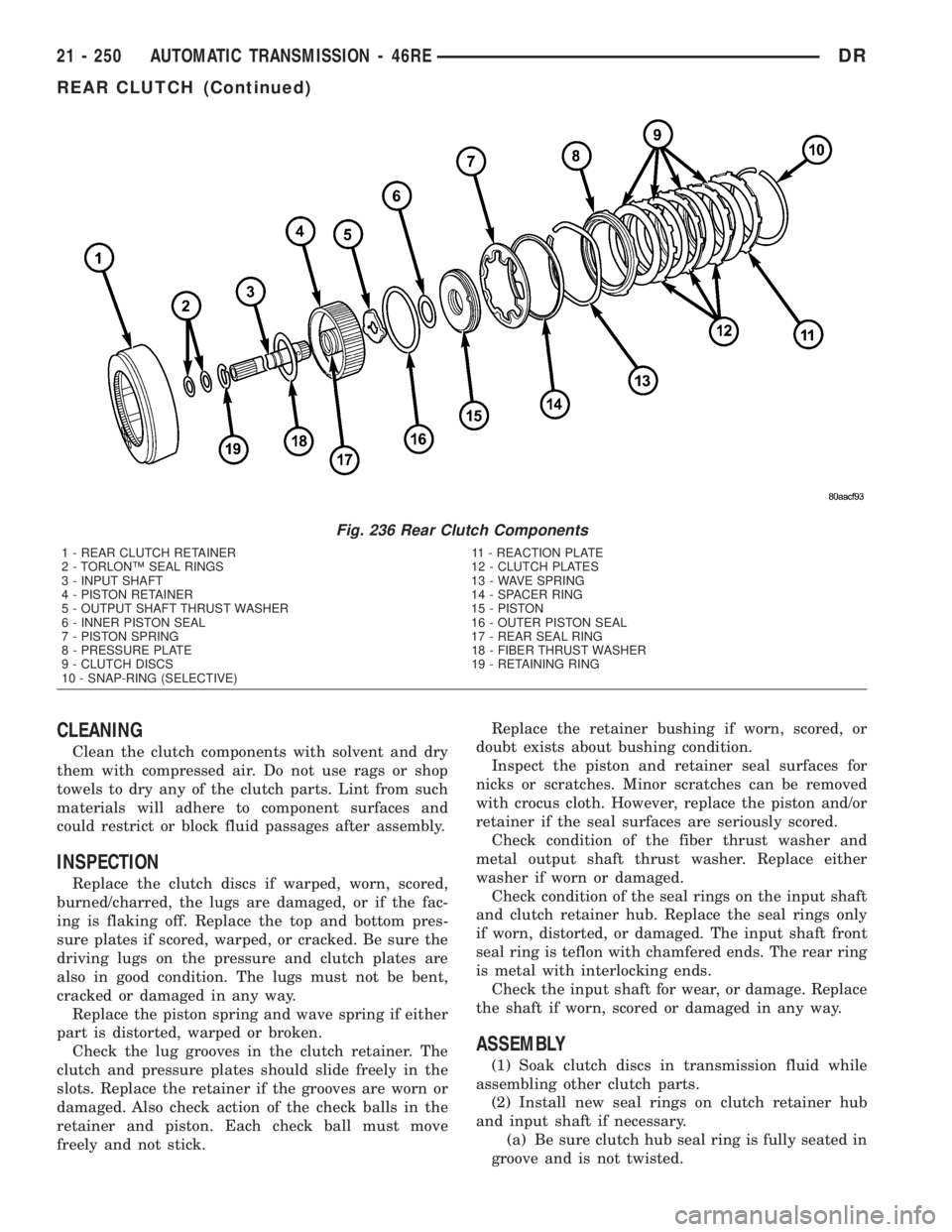
(2) Install new seal rings on clutch retainer hub
and input shaft if necessary.
(a) Be sure clutch hub seal ring is fully seated in
groove and is not twisted.
Fig. 236 Rear Clutch Components
1 - REAR CLUTCH RETAINER 11 - REACTION PLATE
2 - TORLONŸ SEAL RINGS 12 - CLUTCH PLATES
3 - INPUT SHAFT 13 - WAVE SPRING
4 - PISTON RETAINER 14 - SPACER RING
5 - OUTPUT SHAFT THRUST WASHER 15 - PISTON
6 - INNER PISTON SEAL 16 - OUTER PISTON SEAL
7 - PISTON SPRING 17 - REAR SEAL RING
8 - PRESSURE PLATE 18 - FIBER THRUST WASHER
9 - CLUTCH DISCS 19 - RETAINING RING
10 - SNAP-RING (SELECTIVE)
21 - 250 AUTOMATIC TRANSMISSION - 46REDR
REAR CLUTCH (Continued)
Page 2101 of 2895
REMOVAL
(1) Remove transmission and torque converter
from vehicle.
(2) Place a suitable drain pan under the converter
housing end of the transmission.
CAUTION: Verify that transmission is secure on the
lifting device or work surface, the center of gravity
of the transmission will shift when the torque con-
verter is removed creating an unstable condition.
The torque converter is a heavy unit. Use caution
when separating the torque converter from the
transmission.
(3) Pull the torque converter forward until the cen-
ter hub clears the oil pump seal.
(4) Separate the torque converter from the trans-
mission.
INSTALLATION
Check converter hub and drive notches for sharp
edges, burrs, scratches, or nicks. Polish the hub and
notches with 320/400 grit paper or crocus cloth if nec-
essary. The hub must be smooth to avoid damaging
the pump seal at installation.
(1) Lubricate oil pump seal lip with transmission
fluid.
(2) Place torque converter in position on transmis-
sion.
CAUTION: Do not damage oil pump seal or bushing
while inserting torque converter into the front of the
transmission.
(3)
Align torque converter to oil pump seal opening.
(4) Insert torque converter hub into oil pump.
(5) While pushing torque converter inward, rotate
converter until converter is fully seated in the oil
pump gears.
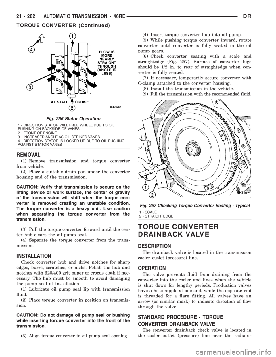
(6) Check converter seating with a scale and
straightedge (Fig. 257). Surface of converter lugs
should be 1/2 in. to rear of straightedge when con-
verter is fully seated.
(7) If necessary, temporarily secure converter with
C-clamp attached to the converter housing.
(8) Install the transmission in the vehicle.
(9)
Fill the transmission with the recommended fluid.
TORQUE CONVERTER
DRAINBACK VALVE
DESCRIPTION
The drainback valve is located in the transmission
cooler outlet (pressure) line.
OPERATION
The valve prevents fluid from draining from the
converter into the cooler and lines when the vehicle
is shut down for lengthy periods. Production valves
have a hose nipple at one end, while the opposite end
is threaded for a flare fitting. All valves have an
arrow (or similar mark) to indicate direction of flow
through the valve.
STANDARD PROCEDURE - TORQUE
CONVERTER DRAINBACK VALVE
The converter drainback check valve is located in
the cooler outlet (pressure) line near the radiator
Fig. 256 Stator Operation
1 - DIRECTION STATOR WILL FREE WHEEL DUE TO OIL
PUSHING ON BACKSIDE OF VANES
2 - FRONT OF ENGINE
3 - INCREASED ANGLE AS OIL STRIKES VANES
4 - DIRECTION STATOR IS LOCKED UP DUE TO OIL PUSHING
AGAINST STATOR VANES
Fig. 257 Checking Torque Converter Seating - Typical
1 - SCALE
2 - STRAIGHTEDGE
21 - 262 AUTOMATIC TRANSMISSION - 46REDR
TORQUE CONVERTER (Continued)
Page 2162 of 2895
(3) Have helper start and run engine at 1600 rpm
for test.
(4) Move transmission shift lever four detents
rearward from full forward position. This is Reverse
range.
(5) Move transmission throttle lever fully forward
then fully rearward and note reading at Gauge
C-3293-SP.
(6) Pressure should be 145 - 175 psi (1000-1207
kPa) with throttle lever forward and increase to 230 -
280 psi (1586-1931 kPa) as lever is gradually moved
rearward.
Test Five - Governor Pressure
This test checks governor operation by measuring
governor pressure response to changes in vehicle
speed. It is usually not necessary to check governor
operation unless shift speeds are incorrect or if the
transmission will not downshift. The test should be
performed on the road or on a hoist that will allow
the rear wheels to rotate freely.
(1) Move 100 psi Test Gauge C-3292 to governor
pressure port.
(2) Move transmission shift lever two detents rear-
ward from full forward position. This is D range.
(3) Have helper start and run engine at curb idle
speed. Then firmly apply service brakes so wheels
will not rotate.
(4) Note governor pressure:
²Governor pressure should be no more than 20.6
kPa (3 psi) at curb idle speed and wheels not rotat-
ing.
²If pressure exceeds 20.6 kPa (3 psi), a fault
exists in governor pressure control system.
(5) Release brakes, slowly increase engine speed,
and observe speedometer and pressure test gauge (do
not exceed 30 mph on speedometer). Governor pres-
sure should increase in proportion to vehicle speed.
Or approximately 6.89 kPa (1 psi) for every 1 mph.
(6) Governor pressure rise should be smooth and
drop back to no more than 20.6 kPa (3 psi), after
engine returns to curb idle and brakes are applied to
prevent wheels from rotating.
(7) Compare results of pressure test with analysis
chart.
Test Six - Transmission In Overdrive Fourth Gear
This test checks line pressure at the overdrive
clutch in fourth gear range. Use 300 psi Test Gauge
C-3293-SP for this test. The test should be performed
on the road or on a chassis dyno.
(1) Remove tachometer; it is not needed for this
test.
(2) Move 300 psi Gauge to overdrive clutch pres-
sure test port. Then remove other gauge and reinstall
test port plug.(3) Lower vehicle.
(4) Turn OD switch on.
(5) Secure test gauge so it can be viewed from
drivers seat.
(6) Start engine and shift into D range.
(7) Increase vehicle speed gradually until 3-4 shift
occurs and note gauge pressure.
(8) Pressure should be 524-565 kPa (76-82 psi)
with closed throttle and increase to 690-896 kPa
(100-130 psi) at 1/2 to 3/4 throttle. Note that pres-
sure can increase to around 965 kPa (140 psi) at full
throttle.
(9) Return to shop or move vehicle off chassis
dyno.
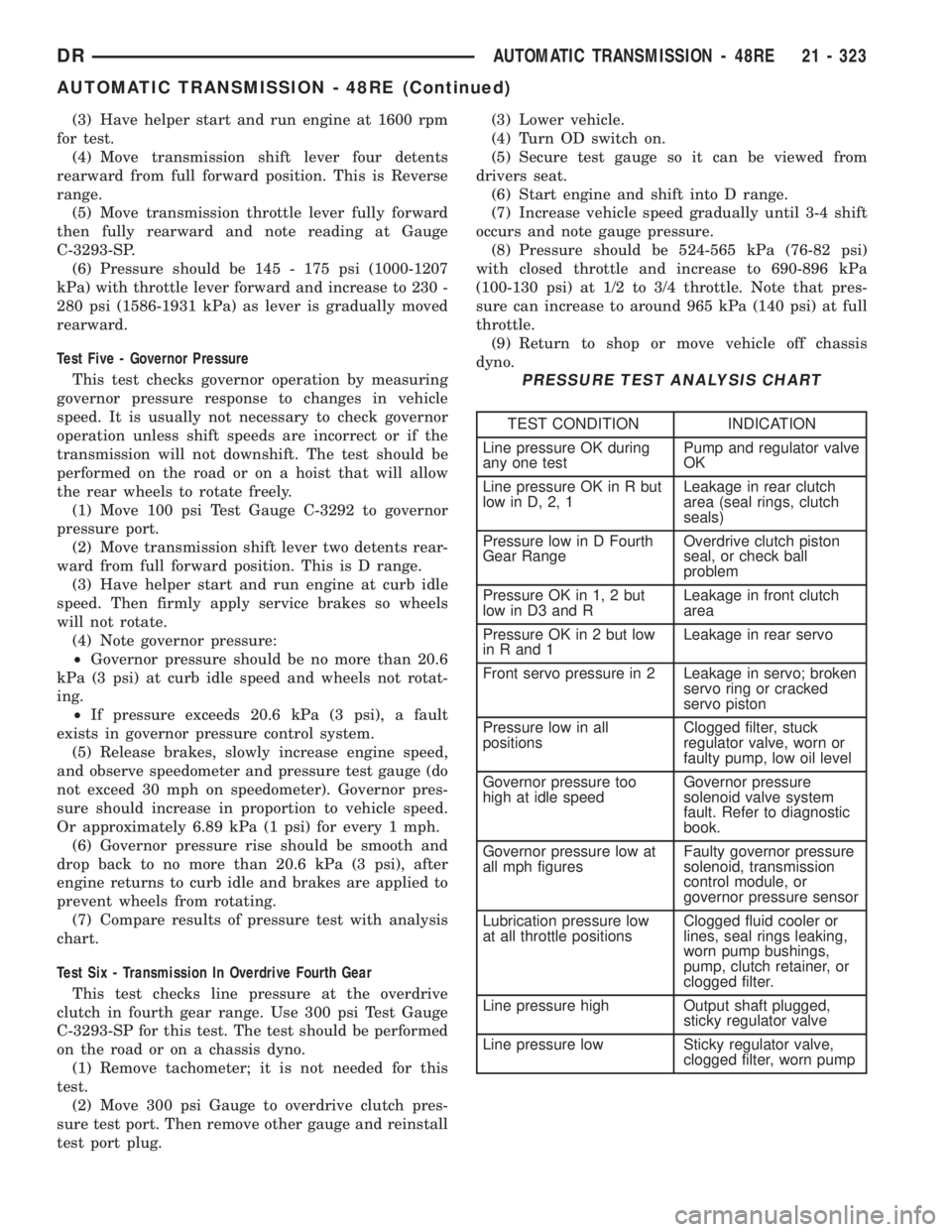
PRESSURE TEST ANALYSIS CHART
TEST CONDITION INDICATION
Line pressure OK during
any one testPump and regulator valve
OK
Line pressure OK in R but
low in D, 2, 1Leakage in rear clutch
area (seal rings, clutch
seals)
Pressure low in D Fourth
Gear RangeOverdrive clutch piston
seal, or check ball
problem
Pressure OK in 1, 2 but
low in D3 and RLeakage in front clutch
area
Pressure OK in 2 but low
in R and 1Leakage in rear servo
Front servo pressure in 2 Leakage in servo; broken
servo ring or cracked
servo piston
Pressure low in all
positionsClogged filter, stuck
regulator valve, worn or
faulty pump, low oil level
Governor pressure too
high at idle speedGovernor pressure
solenoid valve system
fault. Refer to diagnostic
book.
Governor pressure low at
all mph figuresFaulty governor pressure
solenoid, transmission
control module, or
governor pressure sensor
Lubrication pressure low
at all throttle positionsClogged fluid cooler or
lines, seal rings leaking,
worn pump bushings,
pump, clutch retainer, or
clogged filter.
Line pressure high Output shaft plugged,
sticky regulator valve
Line pressure low Sticky regulator valve,
clogged filter, worn pump
DRAUTOMATIC TRANSMISSION - 48RE 21 - 323
AUTOMATIC TRANSMISSION - 48RE (Continued)
Page 2164 of 2895
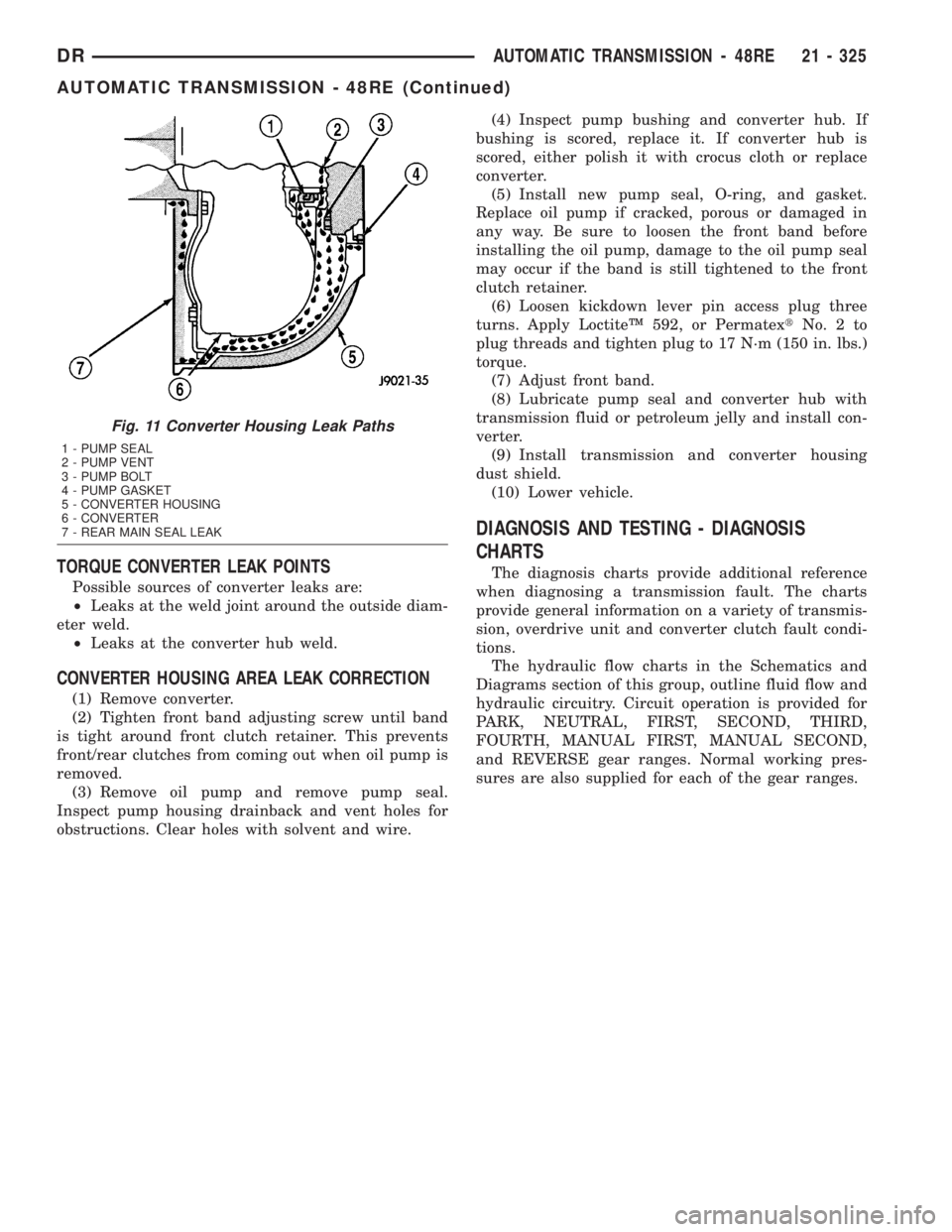
TORQUE CONVERTER LEAK POINTS
Possible sources of converter leaks are:
²Leaks at the weld joint around the outside diam-
eter weld.
²Leaks at the converter hub weld.
CONVERTER HOUSING AREA LEAK CORRECTION
(1) Remove converter.
(2) Tighten front band adjusting screw until band
is tight around front clutch retainer. This prevents
front/rear clutches from coming out when oil pump is
removed.
(3) Remove oil pump and remove pump seal.
Inspect pump housing drainback and vent holes for
obstructions. Clear holes with solvent and wire.(4) Inspect pump bushing and converter hub. If
bushing is scored, replace it. If converter hub is
scored, either polish it with crocus cloth or replace
converter.
(5) Install new pump seal, O-ring, and gasket.
Replace oil pump if cracked, porous or damaged in
any way. Be sure to loosen the front band before
installing the oil pump, damage to the oil pump seal
may occur if the band is still tightened to the front
clutch retainer.
(6) Loosen kickdown lever pin access plug three
turns. Apply LoctiteŸ 592, or PermatextNo.2to
plug threads and tighten plug to 17 N´m (150 in. lbs.)
torque.
(7) Adjust front band.
(8) Lubricate pump seal and converter hub with
transmission fluid or petroleum jelly and install con-
verter.
(9) Install transmission and converter housing
dust shield.
(10) Lower vehicle.
DIAGNOSIS AND TESTING - DIAGNOSIS
CHARTS
The diagnosis charts provide additional reference
when diagnosing a transmission fault. The charts
provide general information on a variety of transmis-
sion, overdrive unit and converter clutch fault condi-
tions.
The hydraulic flow charts in the Schematics and
Diagrams section of this group, outline fluid flow and
hydraulic circuitry. Circuit operation is provided for
PARK, NEUTRAL, FIRST, SECOND, THIRD,
FOURTH, MANUAL FIRST, MANUAL SECOND,
and REVERSE gear ranges. Normal working pres-
sures are also supplied for each of the gear ranges.
Fig. 11 Converter Housing Leak Paths
1 - PUMP SEAL
2 - PUMP VENT
3 - PUMP BOLT
4 - PUMP GASKET
5 - CONVERTER HOUSING
6 - CONVERTER
7 - REAR MAIN SEAL LEAK
DRAUTOMATIC TRANSMISSION - 48RE 21 - 325
AUTOMATIC TRANSMISSION - 48RE (Continued)
Page 2165 of 2895
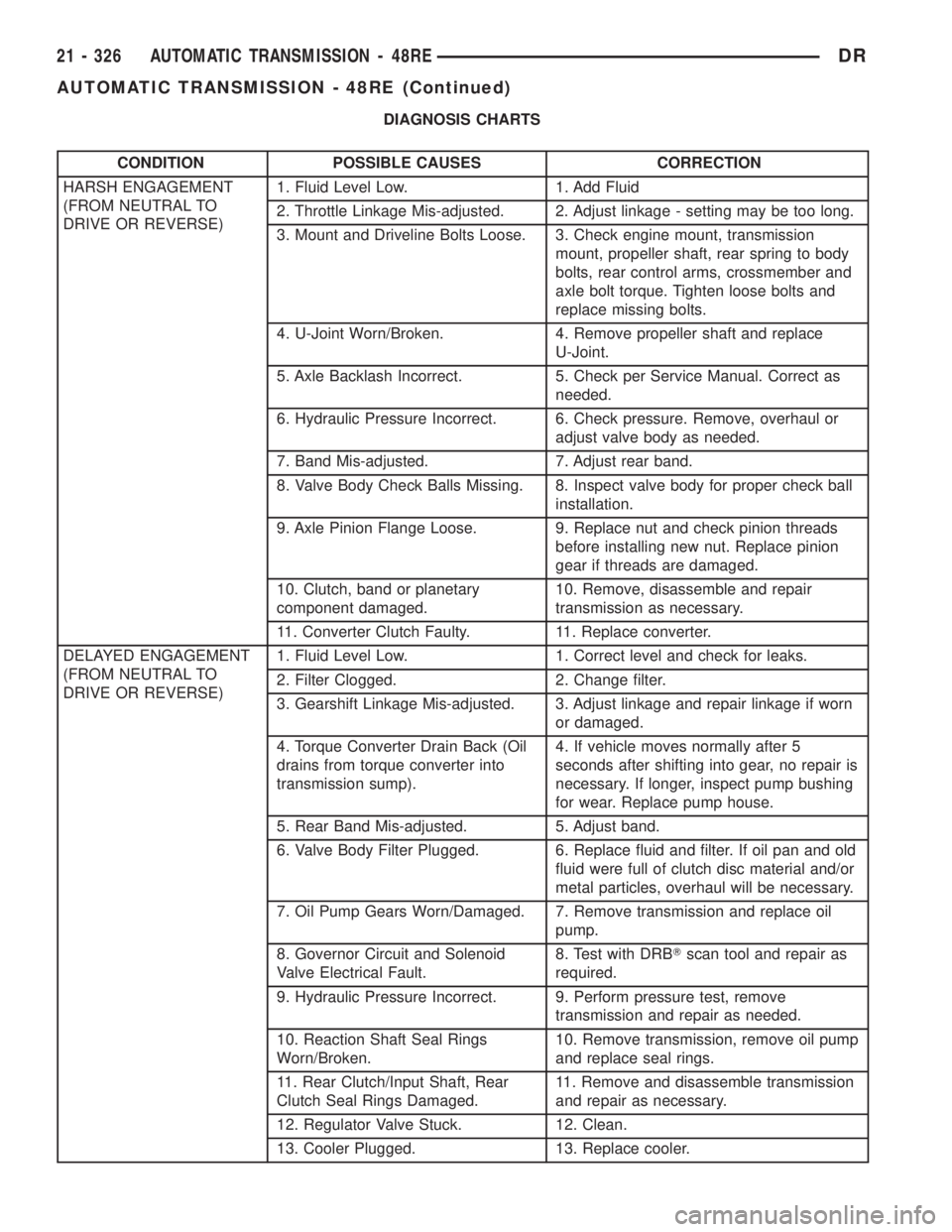
DIAGNOSIS CHARTS
CONDITION POSSIBLE CAUSES CORRECTION
HARSH ENGAGEMENT
(FROM NEUTRAL TO
DRIVE OR REVERSE)1. Fluid Level Low. 1. Add Fluid
2. Throttle Linkage Mis-adjusted. 2. Adjust linkage - setting may be too long.
3. Mount and Driveline Bolts Loose. 3. Check engine mount, transmission
mount, propeller shaft, rear spring to body
bolts, rear control arms, crossmember and
axle bolt torque. Tighten loose bolts and
replace missing bolts.
4. U-Joint Worn/Broken. 4. Remove propeller shaft and replace
U-Joint.
5. Axle Backlash Incorrect. 5. Check per Service Manual. Correct as
needed.
6. Hydraulic Pressure Incorrect. 6. Check pressure. Remove, overhaul or
adjust valve body as needed.
7. Band Mis-adjusted. 7. Adjust rear band.
8. Valve Body Check Balls Missing. 8. Inspect valve body for proper check ball
installation.
9. Axle Pinion Flange Loose. 9. Replace nut and check pinion threads
before installing new nut. Replace pinion
gear if threads are damaged.
10. Clutch, band or planetary
component damaged.10. Remove, disassemble and repair
transmission as necessary.
11. Converter Clutch Faulty. 11. Replace converter.
DELAYED ENGAGEMENT
(FROM NEUTRAL TO
DRIVE OR REVERSE)1. Fluid Level Low. 1. Correct level and check for leaks.
2. Filter Clogged. 2. Change filter.
3. Gearshift Linkage Mis-adjusted. 3. Adjust linkage and repair linkage if worn
or damaged.
4. Torque Converter Drain Back (Oil
drains from torque converter into
transmission sump).4. If vehicle moves normally after 5
seconds after shifting into gear, no repair is
necessary. If longer, inspect pump bushing
for wear. Replace pump house.
5. Rear Band Mis-adjusted. 5. Adjust band.
6. Valve Body Filter Plugged. 6. Replace fluid and filter. If oil pan and old
fluid were full of clutch disc material and/or
metal particles, overhaul will be necessary.
7. Oil Pump Gears Worn/Damaged. 7. Remove transmission and replace oil
pump.
8. Governor Circuit and Solenoid
Valve Electrical Fault.8. Test with DRBTscan tool and repair as
required.
9. Hydraulic Pressure Incorrect. 9. Perform pressure test, remove
transmission and repair as needed.
10. Reaction Shaft Seal Rings
Worn/Broken.10. Remove transmission, remove oil pump
and replace seal rings.
11. Rear Clutch/Input Shaft, Rear
Clutch Seal Rings Damaged.11. Remove and disassemble transmission
and repair as necessary.
12. Regulator Valve Stuck. 12. Clean.
13. Cooler Plugged. 13. Replace cooler.
21 - 326 AUTOMATIC TRANSMISSION - 48REDR
AUTOMATIC TRANSMISSION - 48RE (Continued)