bushing DODGE RAM 2003 Service Repair Manual
[x] Cancel search | Manufacturer: DODGE, Model Year: 2003, Model line: RAM, Model: DODGE RAM 2003Pages: 2895, PDF Size: 83.15 MB
Page 2442 of 2895
REAR RETAINER COMPONENTS
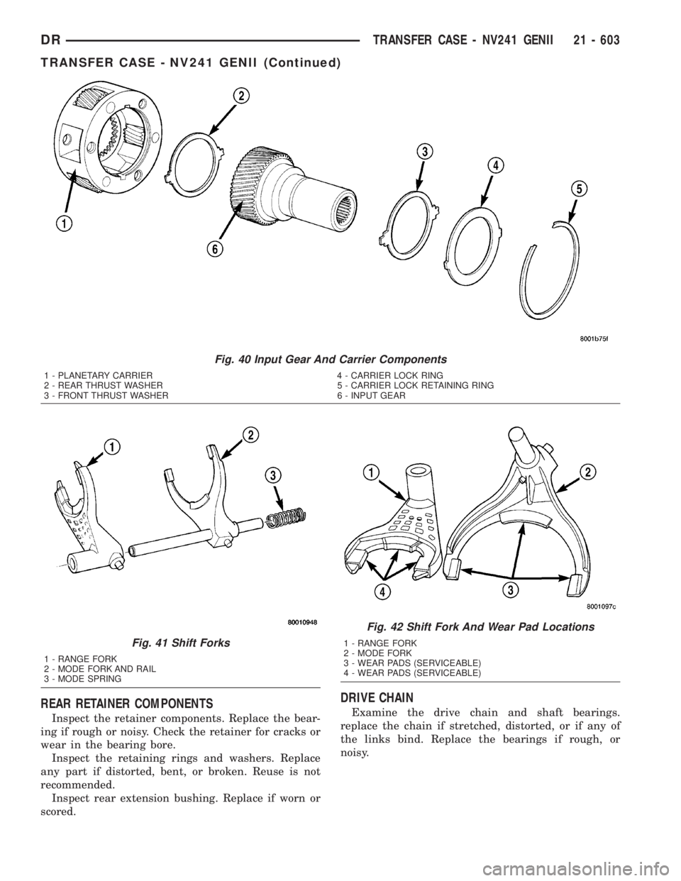
Inspect the retainer components. Replace the bear-
ing if rough or noisy. Check the retainer for cracks or
wear in the bearing bore.
Inspect the retaining rings and washers. Replace
any part if distorted, bent, or broken. Reuse is not
recommended.
Inspect rear extension bushing. Replace if worn or
scored.
DRIVE CHAIN
Examine the drive chain and shaft bearings.
replace the chain if stretched, distorted, or if any of
the links bind. Replace the bearings if rough, or
noisy.
Fig. 40 Input Gear And Carrier Components
1 - PLANETARY CARRIER 4 - CARRIER LOCK RING
2 - REAR THRUST WASHER 5 - CARRIER LOCK RETAINING RING
3 - FRONT THRUST WASHER 6 - INPUT GEAR
Fig. 41 Shift Forks
1 - RANGE FORK
2 - MODE FORK AND RAIL
3 - MODE SPRING
Fig. 42 Shift Fork And Wear Pad Locations
1 - RANGE FORK
2 - MODE FORK
3 - WEAR PADS (SERVICEABLE)
4 - WEAR PADS (SERVICEABLE)
DRTRANSFER CASE - NV241 GENII 21 - 603
TRANSFER CASE - NV241 GENII (Continued)
Page 2454 of 2895

SPECIAL TOOLS
TRANSFER CASE - NV241/NV243
Handle, Universal - C-4171
Installer, Seal - 6888
Installer, Bearing - 6953
Installer, Seal - C-4210
Remover, Bushing - 6957
Installer, Bushing - 8157
Installer, Seal - D-163
Installer, Seal - 7884
Installer, Bushing - 5066
DRTRANSFER CASE - NV241 GENII 21 - 615
TRANSFER CASE - NV241 GENII (Continued)
Page 2455 of 2895
EXTENSION HOUSING
BUSHING AND SEAL
REMOVAL
(1) Raise and support vehicle.
(2) Remove rear propeller shaft. (Refer to 3 - DIF-
FERENTIAL & DRIVELINE/PROPELLER SHAFT/
PROPELLER SHAFT - REMOVAL)
(3) Using a suitable pry tool or slide-hammer
mounted screw, remove the extension housing seal.
(4) Using Remover 8158, remove bushing from
extension housing.
INSTALLATION
(1) Clean fluid residue from sealing surface and
inspect for defects.
(2) Position replacement bushing in extension
housing with fluid port in bushing aligned with slot
in housing.
(3) Using Installer 8157, drive bushing into hous-
ing until installer seats against case.
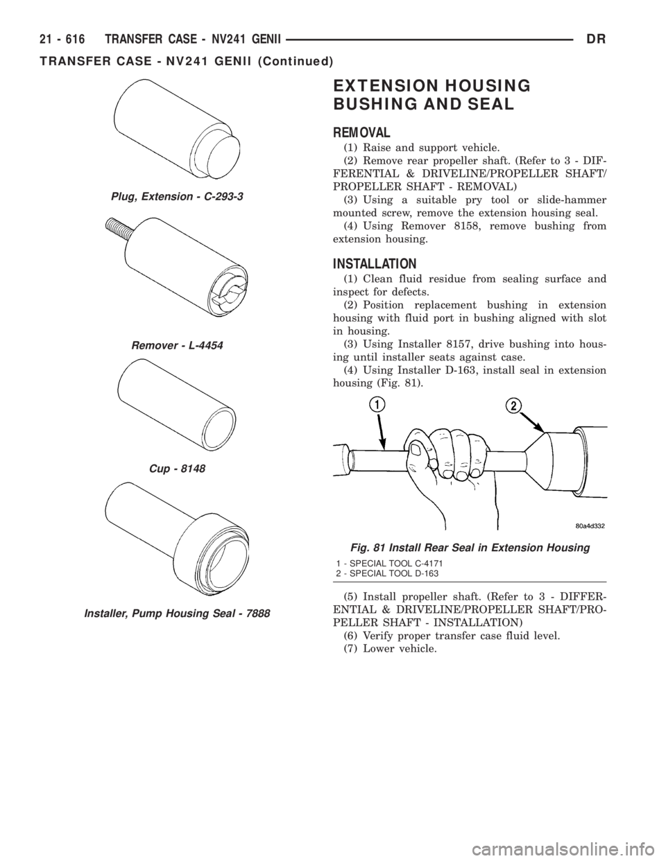
(4) Using Installer D-163, install seal in extension
housing (Fig. 81).
(5) Install propeller shaft. (Refer to 3 - DIFFER-
ENTIAL & DRIVELINE/PROPELLER SHAFT/PRO-
PELLER SHAFT - INSTALLATION)
(6) Verify proper transfer case fluid level.
(7) Lower vehicle.
Plug, Extension - C-293-3
Remover - L-4454
Cup - 8148
Installer, Pump Housing Seal - 7888
Fig. 81 Install Rear Seal in Extension Housing
1 - SPECIAL TOOL C-4171
2 - SPECIAL TOOL D-163
21 - 616 TRANSFER CASE - NV241 GENIIDR
TRANSFER CASE - NV241 GENII (Continued)
Page 2463 of 2895
SHIFT MECHANISM
The transfer case is operated by an adjustable floor
mounted shift linkage. The transfer case shift lever
is directly attached to the shift sector. The sector
operates the range and mode forks within the trans-
fer case.A straight line shift pattern is used with a NEU-
TRAL detent. Lever range positions are imprinted in
the shift knob.
SHIFTING
The transfer case can be shifted between the 2H
and 4H operating ranges while the vehicle is in
motion. The vehicle must have the transmission
placed in NEUTRAL, or the clutch depressed in the
case of a manual transmission, and be moving less
than 2-3 MPH when shifting into and out of the 4L
operating range.
DIAGNOSIS AND TESTING - TRANSFER CASE -
NV271
Before beginning repair on a suspected transfer
case malfunction, check all other driveline compo-
nents beforehand.
The actual cause of a problem may be related to
such items as: front hubs, axles, propeller shafts,
wheels and tires, transmission, or clutch instead. If
all other driveline components are in good condition
and operating properly, refer to the Diagnosis Chart
for further information.
DIAGNOSIS CHART
Condition Possible Cause Correction
Transfer Case difficult to shift or will
not shift into desired range.1) Vehicle speed too great to permit
shifting.1) Stop vehicle and shift into
desired range. Or, reduce speed to
below 3-4 km/h (2-3 mph) before
attempting the shift.
2) If vehicle was operated for an
extended period in 4H on a dry
paved surface, the driveline torque
load may be causing a bind.2) Stop vehicle and shift the
transmission into neutral. Shift the
transfer case to 2H and operate
vehicle in 2H on dry paved
surfaces.
3) Transfer case external shift
linkage binding.3) Lubricate, repair, or replace
linkage bushings, or tighten loose
components as necessary.
4) Insufficient or incorrect lubricant. 4) Drain and refill to edge of fill hole
with MoparTATF +4, Automatic
Transmission fluid.
5) Internal components binding,
worn, or damaged.5) Disassemble the transfer case
and replace worn or damaged
components as necessary.
Transfer Case noisy in all operating
ranges.1) Insufficient or incorrect lubricant. 1) Drain and refill to edge of fill hole
with MoparTATF +4, Automatic
Transmission fluid.
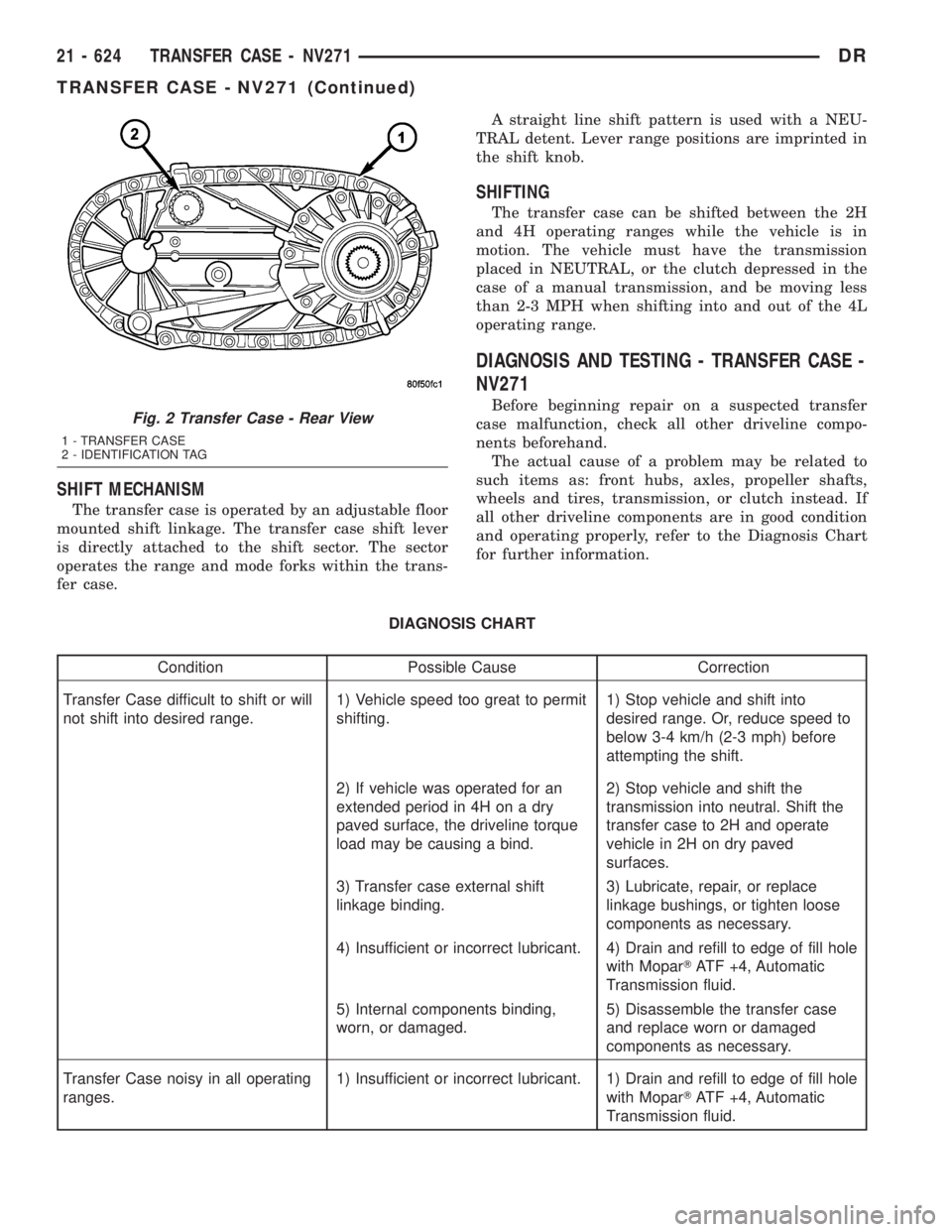
Fig. 2 Transfer Case - Rear View
1 - TRANSFER CASE
2 - IDENTIFICATION TAG
21 - 624 TRANSFER CASE - NV271DR
TRANSFER CASE - NV271 (Continued)
Page 2497 of 2895
TRANSFER CASE - NV243
TABLE OF CONTENTS
page page
TRANSFER CASE - NV243
DESCRIPTION........................658
OPERATION..........................659
DIAGNOSIS AND TESTING - TRANSFER
CASE - NV243.......................659
REMOVAL............................660
DISASSEMBLY........................660
CLEANING...........................668
INSPECTION.........................668
ASSEMBLY...........................670
INSTALLATION........................679
SPECIFICATIONS
TRANSFER CASE - NV243.............680
SPECIAL TOOLS
TRANSFER CASE - NV241/NV243........680
EXTENSION HOUSING BUSHING AND SEAL
REMOVAL............................682
INSTALLATION........................682FLUID
STANDARD PROCEDURE - FLUID DRAIN AND
REFILL............................682
FRONT OUTPUT SHAFT SEAL
REMOVAL............................683
INSTALLATION........................683
MODE SENSOR
DESCRIPTION........................684
OPERATION..........................684
SELECTOR SWITCH
DESCRIPTION........................685
OPERATION..........................685
SHIFT MOTOR
DESCRIPTION........................686
OPERATION..........................686
REMOVAL............................686
INSTALLATION........................686
TRANSFER CASE - NV243
DESCRIPTION
The NV243 is an electronically controlled part-time
transfer case with a low range gear reduction system.
The NV243 has three operating ranges plus a NEU-
TRAL position. The low range system provides a gear
reduction ratio for increased low speed torque capa-
bility.
The geartrain is mounted in two aluminum case
halves attached with bolts. The mainshaft front and
rear bearings are mounted in aluminum retainer
housings bolted to the case halves.
OPERATING RANGES
Transfer case operating ranges are:
²2WD (2-wheel drive)
²4HI (4-wheel drive)
²4LO (4-wheel drive low range)
²NEUTRAL
The 2WD range is for use on any road surface at
any time.The 4HI and 4LO ranges are for off road use only.
They are not for use on hard surface roads. The only
exception being when the road surface is wet or slip-
pery or covered by ice and snow.
The low range reduction gear system is operative
in 4LO range only. This range is for extra pulling
power in off road situations. Low range reduction
ratio is 2.72:1.
SHIFT MECHANISM
Operating ranges are selected with a dash
mounted shift selector switch. The shift selector
switch provides a input to the Transfer Case Control
Module (TCCM) to indicate the driver's desire to
change operating ranges. The TCCM uses this input,
along with input from the transfer case mounted
mode sensor and information from the vehicle's bus,
to determine if a shift is permitted. If the TCCM
decides the shift is permitted, the TCCM controls the
shift motor, mounted to the exterior of the transfer
case, to perform the shift.
21 - 658 TRANSFER CASE - NV243DR
Page 2509 of 2895
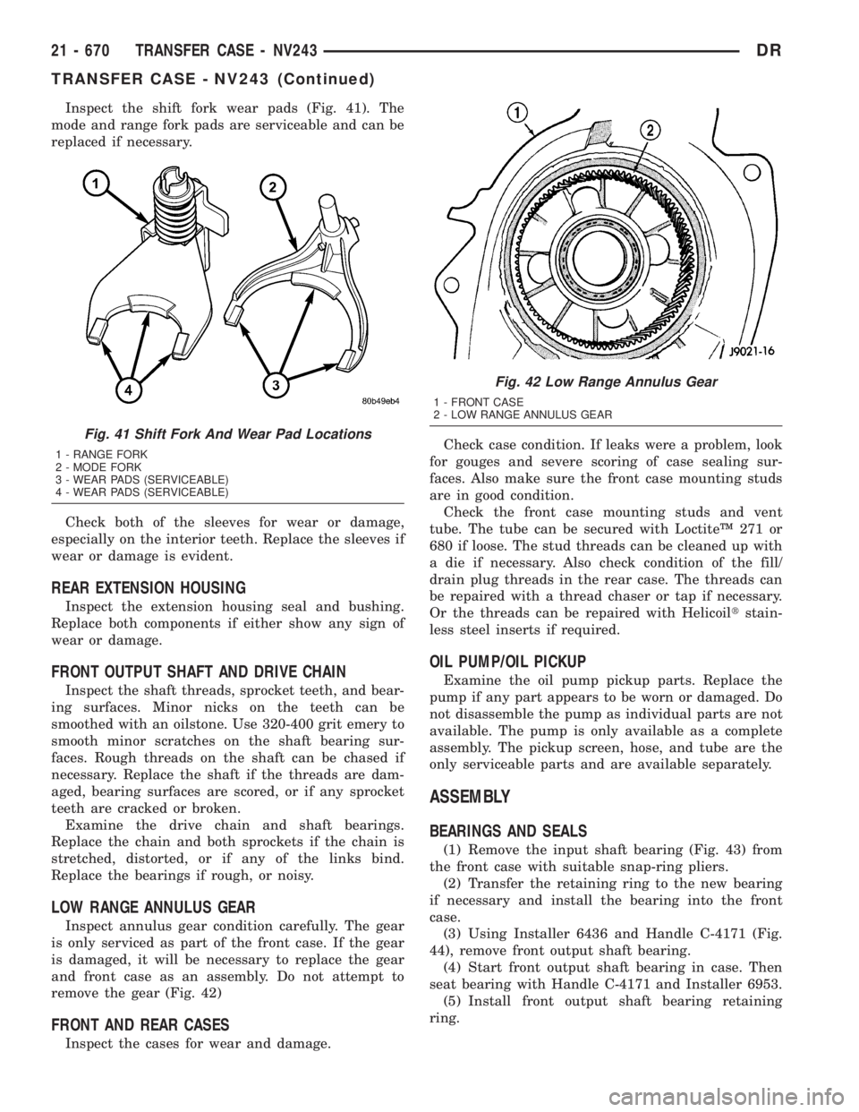
Inspect the shift fork wear pads (Fig. 41). The
mode and range fork pads are serviceable and can be
replaced if necessary.
Check both of the sleeves for wear or damage,
especially on the interior teeth. Replace the sleeves if
wear or damage is evident.
REAR EXTENSION HOUSING
Inspect the extension housing seal and bushing.
Replace both components if either show any sign of
wear or damage.
FRONT OUTPUT SHAFT AND DRIVE CHAIN
Inspect the shaft threads, sprocket teeth, and bear-
ing surfaces. Minor nicks on the teeth can be
smoothed with an oilstone. Use 320-400 grit emery to
smooth minor scratches on the shaft bearing sur-
faces. Rough threads on the shaft can be chased if
necessary. Replace the shaft if the threads are dam-
aged, bearing surfaces are scored, or if any sprocket
teeth are cracked or broken.
Examine the drive chain and shaft bearings.
Replace the chain and both sprockets if the chain is
stretched, distorted, or if any of the links bind.
Replace the bearings if rough, or noisy.
LOW RANGE ANNULUS GEAR
Inspect annulus gear condition carefully. The gear
is only serviced as part of the front case. If the gear
is damaged, it will be necessary to replace the gear
and front case as an assembly. Do not attempt to
remove the gear (Fig. 42)
FRONT AND REAR CASES
Inspect the cases for wear and damage.Check case condition. If leaks were a problem, look
for gouges and severe scoring of case sealing sur-
faces. Also make sure the front case mounting studs
are in good condition.
Check the front case mounting studs and vent
tube. The tube can be secured with LoctiteŸ 271 or
680 if loose. The stud threads can be cleaned up with
a die if necessary. Also check condition of the fill/
drain plug threads in the rear case. The threads can
be repaired with a thread chaser or tap if necessary.
Or the threads can be repaired with Helicoiltstain-
less steel inserts if required.
OIL PUMP/OIL PICKUP
Examine the oil pump pickup parts. Replace the
pump if any part appears to be worn or damaged. Do
not disassemble the pump as individual parts are not
available. The pump is only available as a complete
assembly. The pickup screen, hose, and tube are the
only serviceable parts and are available separately.
ASSEMBLY
BEARINGS AND SEALS
(1) Remove the input shaft bearing (Fig. 43) from
the front case with suitable snap-ring pliers.
(2) Transfer the retaining ring to the new bearing
if necessary and install the bearing into the front
case.
(3) Using Installer 6436 and Handle C-4171 (Fig.
44), remove front output shaft bearing.
(4) Start front output shaft bearing in case. Then
seat bearing with Handle C-4171 and Installer 6953.
(5) Install front output shaft bearing retaining
ring.
Fig. 41 Shift Fork And Wear Pad Locations
1 - RANGE FORK
2 - MODE FORK
3 - WEAR PADS (SERVICEABLE)
4 - WEAR PADS (SERVICEABLE)
Fig. 42 Low Range Annulus Gear
1 - FRONT CASE
2 - LOW RANGE ANNULUS GEAR
21 - 670 TRANSFER CASE - NV243DR
TRANSFER CASE - NV243 (Continued)
Page 2519 of 2895
SPECIFICATIONS
TRANSFER CASE - NV243
TORQUE SPECIFICATIONS
DESCRIPTION N-m Ft. Lbs. In. Lbs.
Plug, Detent 16-24 12-18 -
Plug, Drain/Fill 40-45 30-40 -
Bolt, Extension Housing 16-24 12-18 -
Bolt, Case Half 20-27 15-24 -
Screw, Oil Pump 12-16 8-12 -
Nuts, Mounting 30-41 20-30 -
Bolts, Shift Motor and
Mode Sensor Assembly16-24 12-18 -
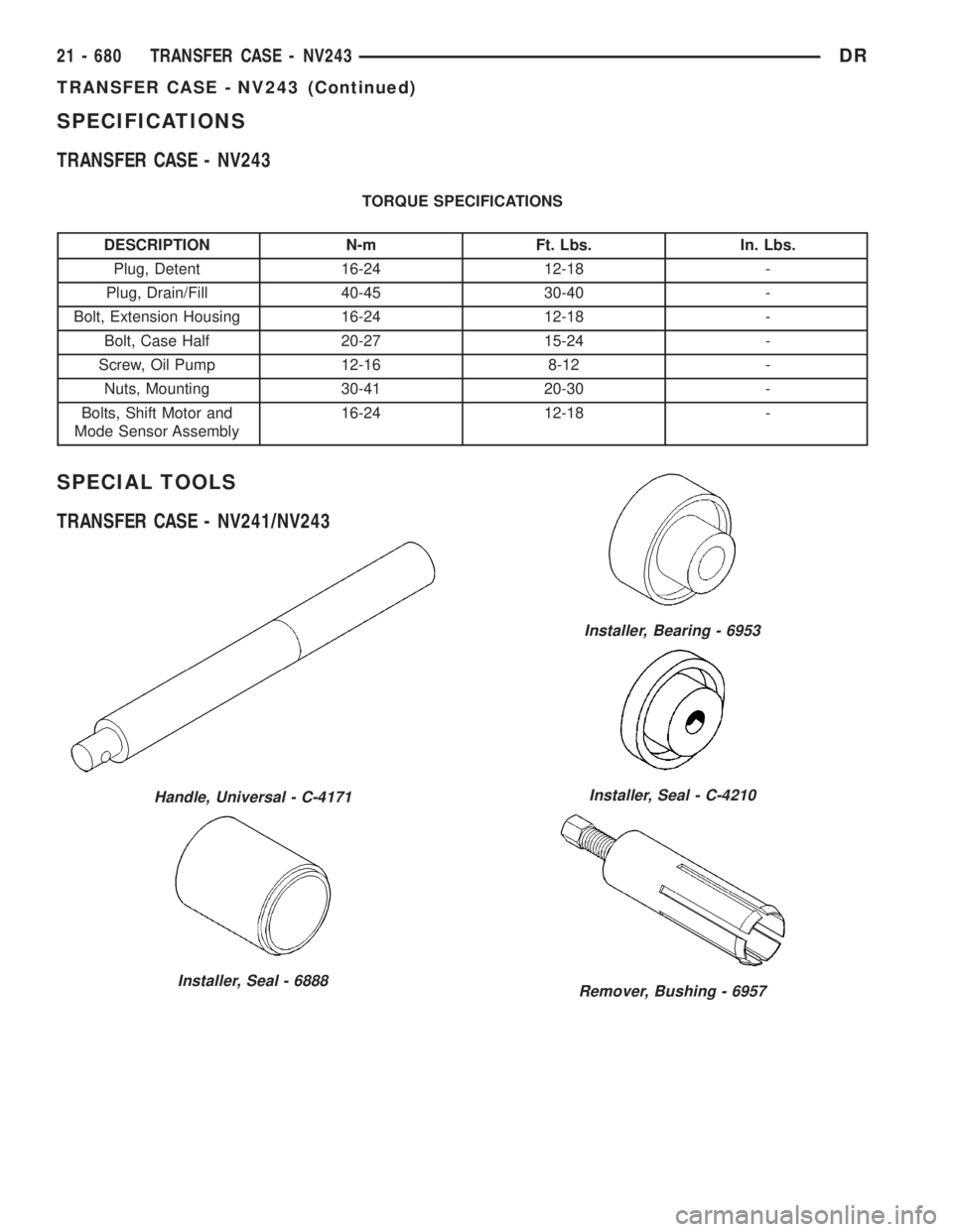
SPECIAL TOOLS
TRANSFER CASE - NV241/NV243
Handle, Universal - C-4171
Installer, Seal - 6888
Installer, Bearing - 6953
Installer, Seal - C-4210
Remover, Bushing - 6957
21 - 680 TRANSFER CASE - NV243DR
TRANSFER CASE - NV243 (Continued)
Page 2520 of 2895
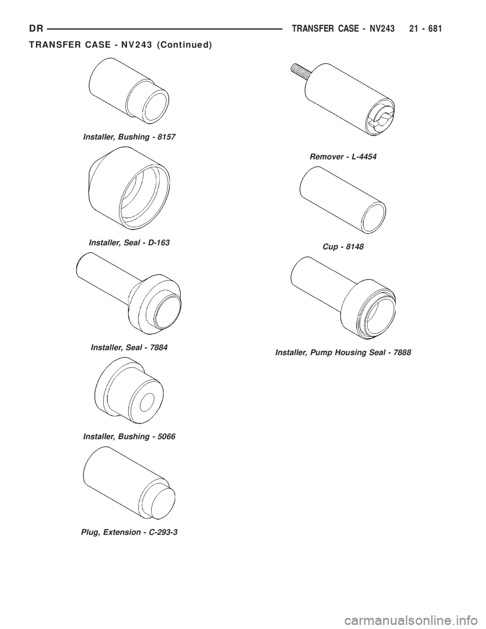
Installer, Bushing - 8157
Installer, Seal - D-163
Installer, Seal - 7884
Installer, Bushing - 5066
Plug, Extension - C-293-3
Remover - L-4454
Cup - 8148
Installer, Pump Housing Seal - 7888
DRTRANSFER CASE - NV243 21 - 681
TRANSFER CASE - NV243 (Continued)
Page 2521 of 2895
EXTENSION HOUSING
BUSHING AND SEAL
REMOVAL
(1) Raise and support vehicle.
(2) Remove rear propeller shaft. (Refer to 3 - DIF-
FERENTIAL & DRIVELINE/PROPELLER SHAFT/
PROPELLER SHAFT - REMOVAL)
(3) Using a suitable pry tool or slide-hammer
mounted screw, remove the extension housing seal.
(4) Using Remover 8158, remove bushing from
extension housing.
INSTALLATION
(1) Clean fluid residue from sealing surface and
inspect for defects.
(2) Position replacement bushing in extension
housing with fluid port in bushing aligned with slot
in housing.
(3) Using Installer 8157, drive bushing into hous-
ing until installer seats against case.
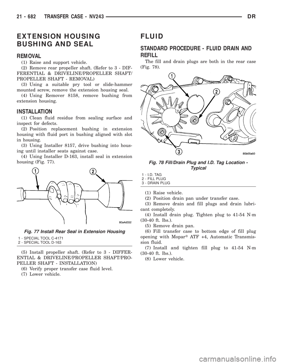
(4) Using Installer D-163, install seal in extension
housing (Fig. 77).
(5) Install propeller shaft. (Refer to 3 - DIFFER-
ENTIAL & DRIVELINE/PROPELLER SHAFT/PRO-
PELLER SHAFT - INSTALLATION)
(6) Verify proper transfer case fluid level.
(7) Lower vehicle.
FLUID
STANDARD PROCEDURE - FLUID DRAIN AND
REFILL
The fill and drain plugs are both in the rear case
(Fig. 78).
(1) Raise vehicle.
(2) Position drain pan under transfer case.
(3) Remove drain and fill plugs and drain lubri-
cant completely.
(4) Install drain plug. Tighten plug to 41-54 N´m
(30-40 ft. lbs.).
(5) Remove drain pan.
(6) Fill transfer case to bottom edge of fill plug
opening with MopartATF +4, Automatic Transmis-
sion fluid.
(7) Install and tighten fill plug to 41-54 N´m
(30-40 ft. lbs.).
(8) Lower vehicle.
Fig. 77 Install Rear Seal in Extension Housing
1 - SPECIAL TOOL C-4171
2 - SPECIAL TOOL D-163
Fig. 78 Fill/Drain Plug and I.D. Tag Location -
Typical
1 - I.D. TAG
2 - FILL PLUG
3 - DRAIN PLUG
21 - 682 TRANSFER CASE - NV243DR
Page 2539 of 2895
SHIFT FORKS/HUBS/SLEEVES
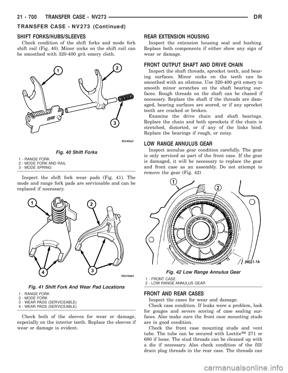
Check condition of the shift forks and mode fork
shift rail (Fig. 40). Minor nicks on the shift rail can
be smoothed with 320-400 grit emery cloth.
Inspect the shift fork wear pads (Fig. 41). The
mode and range fork pads are serviceable and can be
replaced if necessary.
Check both of the sleeves for wear or damage,
especially on the interior teeth. Replace the sleeves if
wear or damage is evident.
REAR EXTENSION HOUSING
Inspect the extension housing seal and bushing.
Replace both components if either show any sign of
wear or damage.
FRONT OUTPUT SHAFT AND DRIVE CHAIN
Inspect the shaft threads, sprocket teeth, and bear-
ing surfaces. Minor nicks on the teeth can be
smoothed with an oilstone. Use 320-400 grit emery to
smooth minor scratches on the shaft bearing sur-
faces. Rough threads on the shaft can be chased if
necessary. Replace the shaft if the threads are dam-
aged, bearing surfaces are scored, or if any sprocket
teeth are cracked or broken.
Examine the drive chain and shaft bearings.
Replace the chain and both sprockets if the chain is
stretched, distorted, or if any of the links bind.
Replace the bearings if rough, or noisy.
LOW RANGE ANNULUS GEAR
Inspect annulus gear condition carefully. The gear
is only serviced as part of the front case. If the gear
is damaged, it will be necessary to replace the gear
and front case as an assembly. Do not attempt to
remove the gear (Fig. 42)
FRONT AND REAR CASES
Inspect the cases for wear and damage.
Check case condition. If leaks were a problem, look
for gouges and severe scoring of case sealing sur-
faces. Also make sure the front case mounting studs
are in good condition.
Check the front case mounting studs and vent
tube. The tube can be secured with LoctiteŸ 271 or
680 if loose. The stud threads can be cleaned up with
a die if necessary. Also check condition of the fill/
drain plug threads in the rear case. The threads can
Fig. 40 Shift Forks
1 - RANGE FORK
2 - MODE FORK AND RAIL
3 - MODE SPRING
Fig. 41 Shift Fork And Wear Pad Locations
1 - RANGE FORK
2 - MODE FORK
3 - WEAR PADS (SERVICEABLE)
4 - WEAR PADS (SERVICEABLE)
Fig. 42 Low Range Annulus Gear
1 - FRONT CASE
2 - LOW RANGE ANNULUS GEAR
21 - 700 TRANSFER CASE - NV273DR
TRANSFER CASE - NV273 (Continued)