bushing DODGE RAM 2003 Service Repair Manual
[x] Cancel search | Manufacturer: DODGE, Model Year: 2003, Model line: RAM, Model: DODGE RAM 2003Pages: 2895, PDF Size: 83.15 MB
Page 2170 of 2895
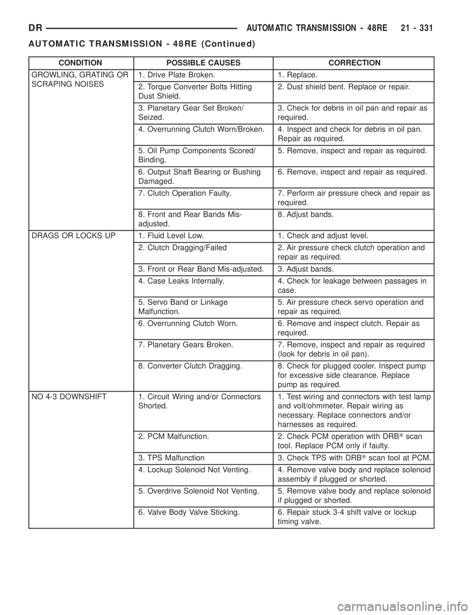
CONDITION POSSIBLE CAUSES CORRECTION
GROWLING, GRATING OR
SCRAPING NOISES1. Drive Plate Broken. 1. Replace.
2. Torque Converter Bolts Hitting
Dust Shield.2. Dust shield bent. Replace or repair.
3. Planetary Gear Set Broken/
Seized.3. Check for debris in oil pan and repair as
required.
4. Overrunning Clutch Worn/Broken. 4. Inspect and check for debris in oil pan.
Repair as required.
5. Oil Pump Components Scored/
Binding.5. Remove, inspect and repair as required.
6. Output Shaft Bearing or Bushing
Damaged.6. Remove, inspect and repair as required.
7. Clutch Operation Faulty. 7. Perform air pressure check and repair as
required.
8. Front and Rear Bands Mis-
adjusted.8. Adjust bands.
DRAGS OR LOCKS UP 1. Fluid Level Low. 1. Check and adjust level.
2. Clutch Dragging/Failed 2. Air pressure check clutch operation and
repair as required.
3. Front or Rear Band Mis-adjusted. 3. Adjust bands.
4. Case Leaks Internally. 4. Check for leakage between passages in
case.
5. Servo Band or Linkage
Malfunction.5. Air pressure check servo operation and
repair as required.
6. Overrunning Clutch Worn. 6. Remove and inspect clutch. Repair as
required.
7. Planetary Gears Broken. 7. Remove, inspect and repair as required
(look for debris in oil pan).
8. Converter Clutch Dragging. 8. Check for plugged cooler. Inspect pump
for excessive side clearance. Replace
pump as required.
NO 4-3 DOWNSHIFT 1. Circuit Wiring and/or Connectors
Shorted.1. Test wiring and connectors with test lamp
and volt/ohmmeter. Repair wiring as
necessary. Replace connectors and/or
harnesses as required.
2. PCM Malfunction. 2. Check PCM operation with DRBTscan
tool. Replace PCM only if faulty.
3. TPS Malfunction 3. Check TPS with DRBTscan tool at PCM.
4. Lockup Solenoid Not Venting. 4. Remove valve body and replace solenoid
assembly if plugged or shorted.
5. Overdrive Solenoid Not Venting. 5. Remove valve body and replace solenoid
if plugged or shorted.
6. Valve Body Valve Sticking. 6. Repair stuck 3-4 shift valve or lockup
timing valve.
DRAUTOMATIC TRANSMISSION - 48RE 21 - 331
AUTOMATIC TRANSMISSION - 48RE (Continued)
Page 2175 of 2895
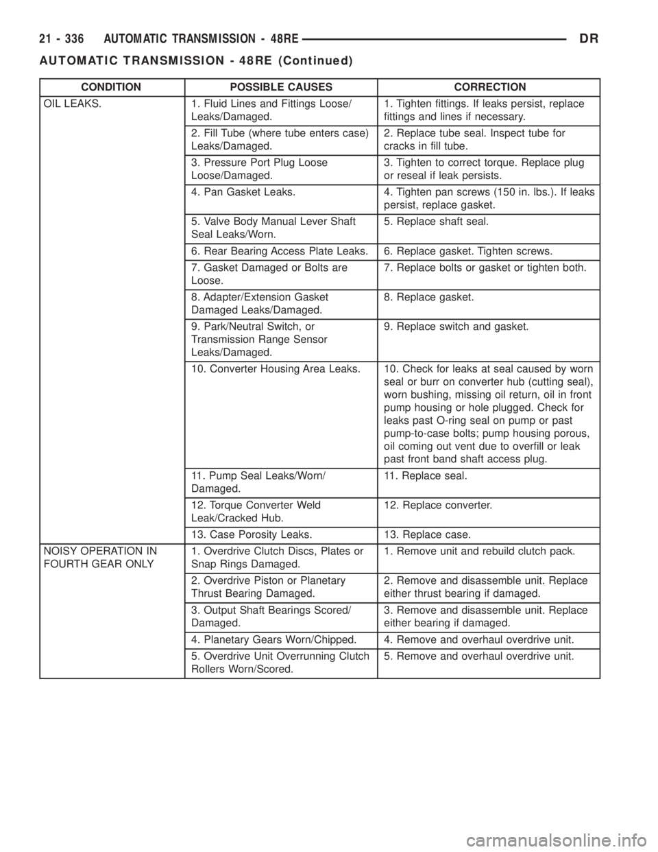
CONDITION POSSIBLE CAUSES CORRECTION
OIL LEAKS. 1. Fluid Lines and Fittings Loose/
Leaks/Damaged.1. Tighten fittings. If leaks persist, replace
fittings and lines if necessary.
2. Fill Tube (where tube enters case)
Leaks/Damaged.2. Replace tube seal. Inspect tube for
cracks in fill tube.
3. Pressure Port Plug Loose
Loose/Damaged.3. Tighten to correct torque. Replace plug
or reseal if leak persists.
4. Pan Gasket Leaks. 4. Tighten pan screws (150 in. lbs.). If leaks
persist, replace gasket.
5. Valve Body Manual Lever Shaft
Seal Leaks/Worn.5. Replace shaft seal.
6. Rear Bearing Access Plate Leaks. 6. Replace gasket. Tighten screws.
7. Gasket Damaged or Bolts are
Loose.7. Replace bolts or gasket or tighten both.
8. Adapter/Extension Gasket
Damaged Leaks/Damaged.8. Replace gasket.
9. Park/Neutral Switch, or
Transmission Range Sensor
Leaks/Damaged.9. Replace switch and gasket.
10. Converter Housing Area Leaks. 10. Check for leaks at seal caused by worn
seal or burr on converter hub (cutting seal),
worn bushing, missing oil return, oil in front
pump housing or hole plugged. Check for
leaks past O-ring seal on pump or past
pump-to-case bolts; pump housing porous,
oil coming out vent due to overfill or leak
past front band shaft access plug.
11. Pump Seal Leaks/Worn/
Damaged.11. Replace seal.
12. Torque Converter Weld
Leak/Cracked Hub.12. Replace converter.
13. Case Porosity Leaks. 13. Replace case.
NOISY OPERATION IN
FOURTH GEAR ONLY1. Overdrive Clutch Discs, Plates or
Snap Rings Damaged.1. Remove unit and rebuild clutch pack.
2. Overdrive Piston or Planetary
Thrust Bearing Damaged.2. Remove and disassemble unit. Replace
either thrust bearing if damaged.
3. Output Shaft Bearings Scored/
Damaged.3. Remove and disassemble unit. Replace
either bearing if damaged.
4. Planetary Gears Worn/Chipped. 4. Remove and overhaul overdrive unit.
5. Overdrive Unit Overrunning Clutch
Rollers Worn/Scored.5. Remove and overhaul overdrive unit.
21 - 336 AUTOMATIC TRANSMISSION - 48REDR
AUTOMATIC TRANSMISSION - 48RE (Continued)
Page 2184 of 2895
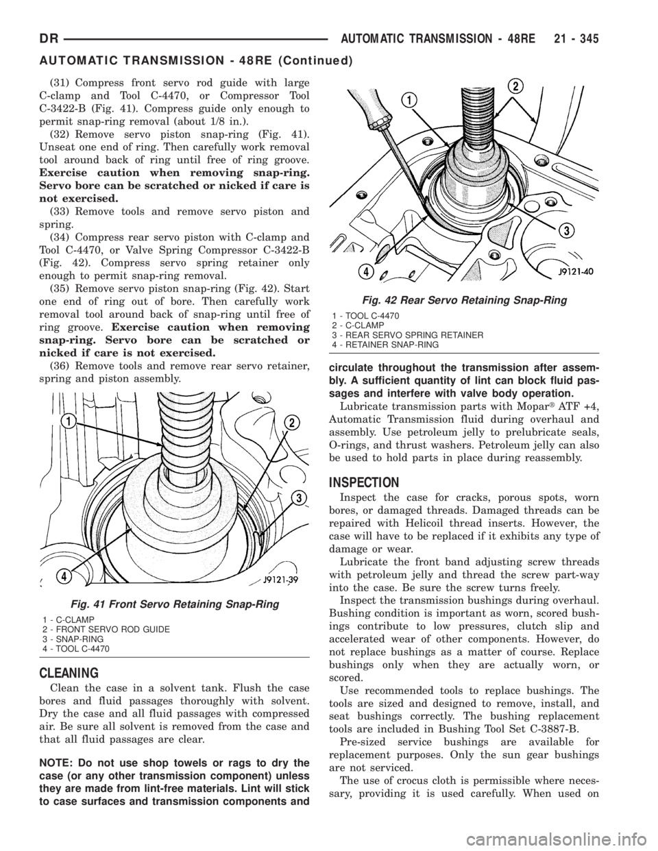
(31) Compress front servo rod guide with large
C-clamp and Tool C-4470, or Compressor Tool
C-3422-B (Fig. 41). Compress guide only enough to
permit snap-ring removal (about 1/8 in.).
(32) Remove servo piston snap-ring (Fig. 41).
Unseat one end of ring. Then carefully work removal
tool around back of ring until free of ring groove.
Exercise caution when removing snap-ring.
Servo bore can be scratched or nicked if care is
not exercised.
(33) Remove tools and remove servo piston and
spring.
(34) Compress rear servo piston with C-clamp and
Tool C-4470, or Valve Spring Compressor C-3422-B
(Fig. 42). Compress servo spring retainer only
enough to permit snap-ring removal.
(35) Remove servo piston snap-ring (Fig. 42). Start
one end of ring out of bore. Then carefully work
removal tool around back of snap-ring until free of
ring groove.Exercise caution when removing
snap-ring. Servo bore can be scratched or
nicked if care is not exercised.
(36) Remove tools and remove rear servo retainer,
spring and piston assembly.
CLEANING
Clean the case in a solvent tank. Flush the case
bores and fluid passages thoroughly with solvent.
Dry the case and all fluid passages with compressed
air. Be sure all solvent is removed from the case and
that all fluid passages are clear.
NOTE: Do not use shop towels or rags to dry the
case (or any other transmission component) unless
they are made from lint-free materials. Lint will stick
to case surfaces and transmission components andcirculate throughout the transmission after assem-
bly. A sufficient quantity of lint can block fluid pas-
sages and interfere with valve body operation.
Lubricate transmission parts with MopartATF +4,
Automatic Transmission fluid during overhaul and
assembly. Use petroleum jelly to prelubricate seals,
O-rings, and thrust washers. Petroleum jelly can also
be used to hold parts in place during reassembly.
INSPECTION
Inspect the case for cracks, porous spots, worn
bores, or damaged threads. Damaged threads can be
repaired with Helicoil thread inserts. However, the
case will have to be replaced if it exhibits any type of
damage or wear.
Lubricate the front band adjusting screw threads
with petroleum jelly and thread the screw part-way
into the case. Be sure the screw turns freely.
Inspect the transmission bushings during overhaul.
Bushing condition is important as worn, scored bush-
ings contribute to low pressures, clutch slip and
accelerated wear of other components. However, do
not replace bushings as a matter of course. Replace
bushings only when they are actually worn, or
scored.
Use recommended tools to replace bushings. The
tools are sized and designed to remove, install, and
seat bushings correctly. The bushing replacement
tools are included in Bushing Tool Set C-3887-B.
Pre-sized service bushings are available for
replacement purposes. Only the sun gear bushings
are not serviced.
The use of crocus cloth is permissible where neces-
sary, providing it is used carefully. When used on
Fig. 41 Front Servo Retaining Snap-Ring
1 - C-CLAMP
2 - FRONT SERVO ROD GUIDE
3 - SNAP-RING
4 - TOOL C-4470
Fig. 42 Rear Servo Retaining Snap-Ring
1 - TOOL C-4470
2 - C-CLAMP
3 - REAR SERVO SPRING RETAINER
4 - RETAINER SNAP-RING
DRAUTOMATIC TRANSMISSION - 48RE 21 - 345
AUTOMATIC TRANSMISSION - 48RE (Continued)
Page 2187 of 2895
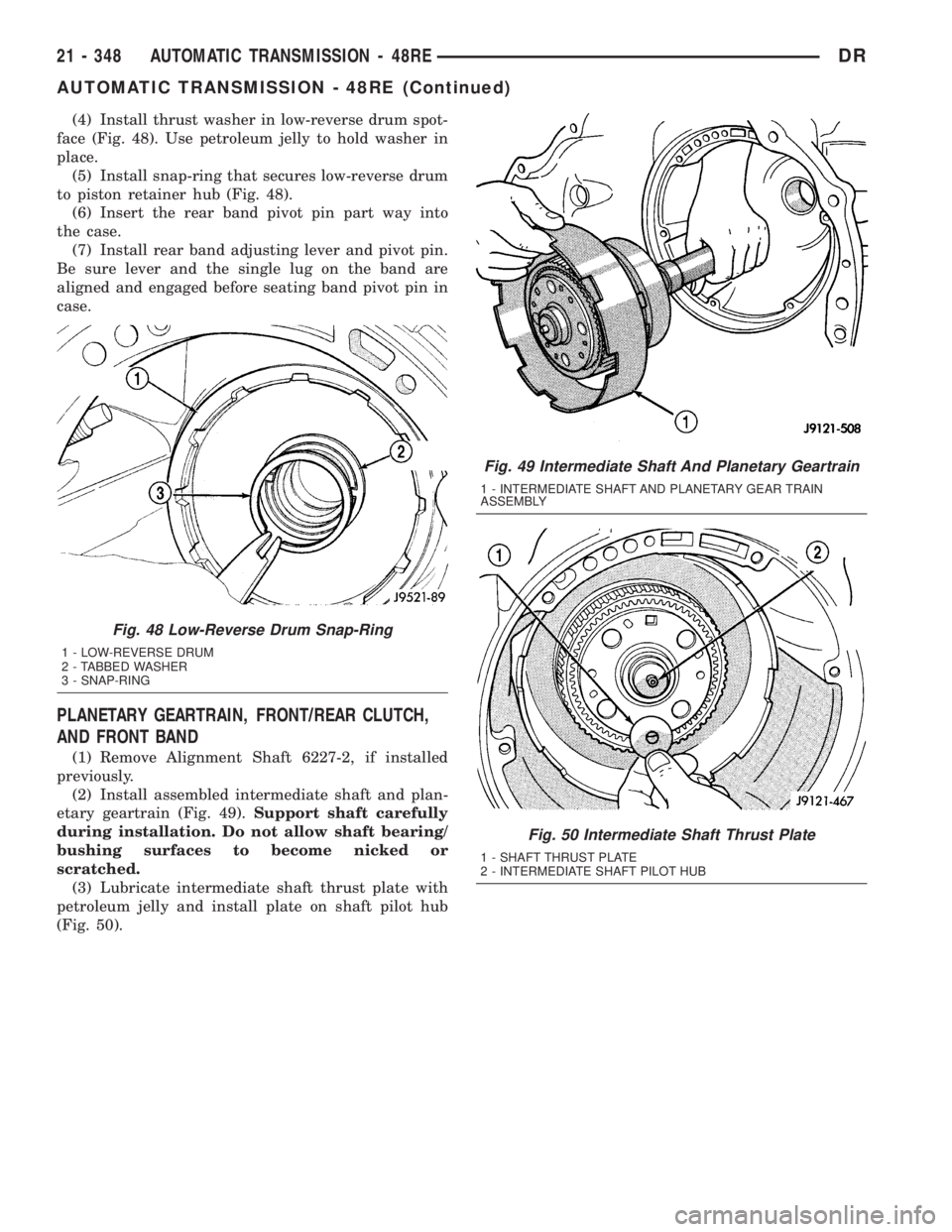
(4) Install thrust washer in low-reverse drum spot-
face (Fig. 48). Use petroleum jelly to hold washer in
place.
(5) Install snap-ring that secures low-reverse drum
to piston retainer hub (Fig. 48).
(6) Insert the rear band pivot pin part way into
the case.
(7) Install rear band adjusting lever and pivot pin.
Be sure lever and the single lug on the band are
aligned and engaged before seating band pivot pin in
case.
PLANETARY GEARTRAIN, FRONT/REAR CLUTCH,
AND FRONT BAND
(1) Remove Alignment Shaft 6227-2, if installed
previously.
(2) Install assembled intermediate shaft and plan-
etary geartrain (Fig. 49).Support shaft carefully
during installation. Do not allow shaft bearing/
bushing surfaces to become nicked or
scratched.
(3) Lubricate intermediate shaft thrust plate with
petroleum jelly and install plate on shaft pilot hub
(Fig. 50).
Fig. 49 Intermediate Shaft And Planetary Geartrain
1 - INTERMEDIATE SHAFT AND PLANETARY GEAR TRAIN
ASSEMBLY
Fig. 50 Intermediate Shaft Thrust Plate
1 - SHAFT THRUST PLATE
2 - INTERMEDIATE SHAFT PILOT HUB
Fig. 48 Low-Reverse Drum Snap-Ring
1 - LOW-REVERSE DRUM
2 - TABBED WASHER
3 - SNAP-RING
21 - 348 AUTOMATIC TRANSMISSION - 48REDR
AUTOMATIC TRANSMISSION - 48RE (Continued)
Page 2210 of 2895
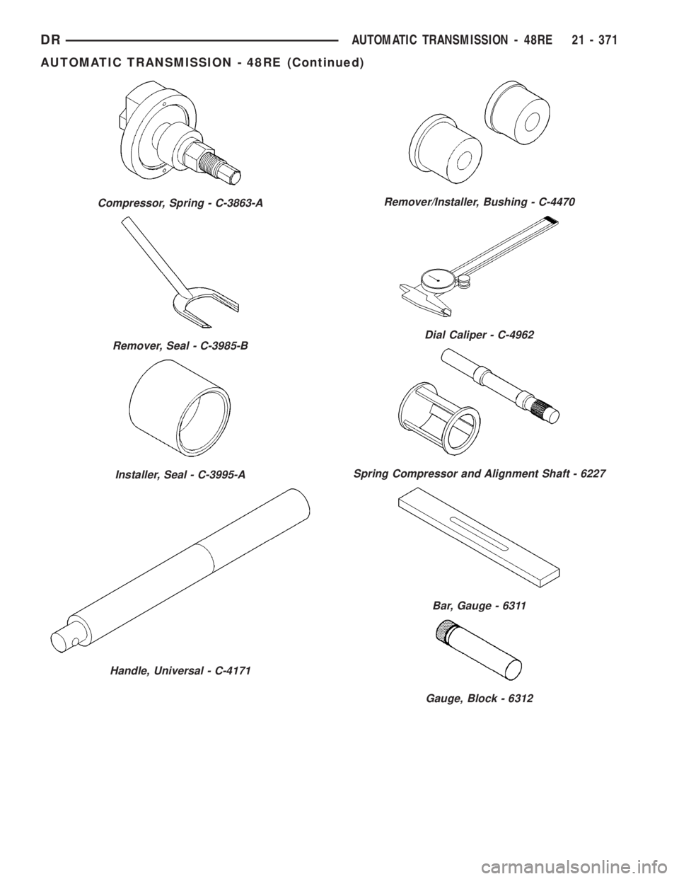
Compressor, Spring - C-3863-A
Remover, Seal - C-3985-B
Installer, Seal - C-3995-A
Handle, Universal - C-4171
Remover/Installer, Bushing - C-4470
Dial Caliper - C-4962
Spring Compressor and Alignment Shaft - 6227
Bar, Gauge - 6311
Gauge, Block - 6312
DRAUTOMATIC TRANSMISSION - 48RE 21 - 371
AUTOMATIC TRANSMISSION - 48RE (Continued)
Page 2224 of 2895
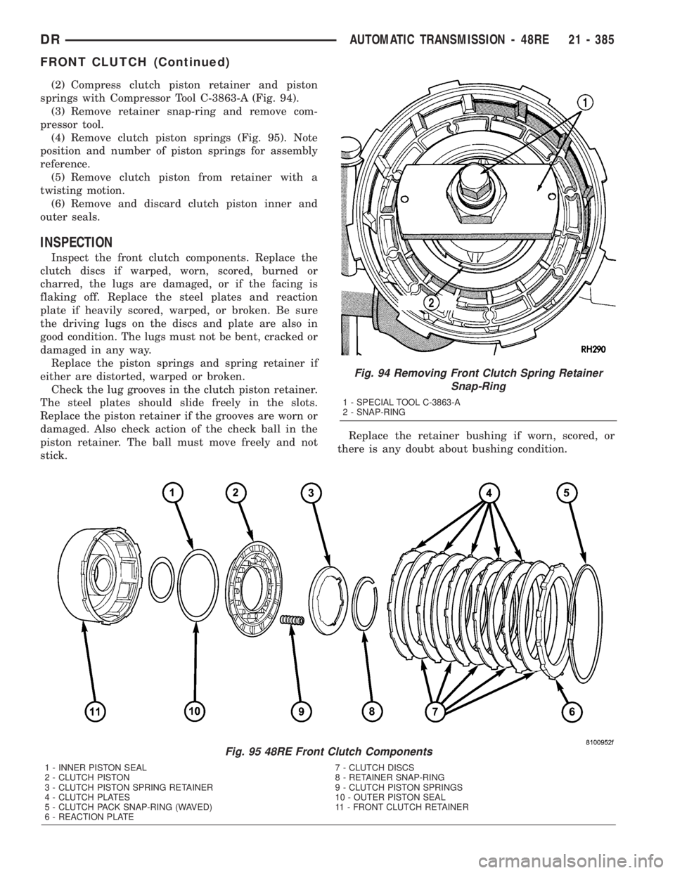
(2) Compress clutch piston retainer and piston
springs with Compressor Tool C-3863-A (Fig. 94).
(3) Remove retainer snap-ring and remove com-
pressor tool.
(4) Remove clutch piston springs (Fig. 95). Note
position and number of piston springs for assembly
reference.
(5) Remove clutch piston from retainer with a
twisting motion.
(6) Remove and discard clutch piston inner and
outer seals.
INSPECTION
Inspect the front clutch components. Replace the
clutch discs if warped, worn, scored, burned or
charred, the lugs are damaged, or if the facing is
flaking off. Replace the steel plates and reaction
plate if heavily scored, warped, or broken. Be sure
the driving lugs on the discs and plate are also in
good condition. The lugs must not be bent, cracked or
damaged in any way.
Replace the piston springs and spring retainer if
either are distorted, warped or broken.
Check the lug grooves in the clutch piston retainer.
The steel plates should slide freely in the slots.
Replace the piston retainer if the grooves are worn or
damaged. Also check action of the check ball in the
piston retainer. The ball must move freely and not
stick.Replace the retainer bushing if worn, scored, or
there is any doubt about bushing condition.
Fig. 94 Removing Front Clutch Spring Retainer
Snap-Ring
1 - SPECIAL TOOL C-3863-A
2 - SNAP-RING
Fig. 95 48RE Front Clutch Components
1 - INNER PISTON SEAL 7 - CLUTCH DISCS
2 - CLUTCH PISTON 8 - RETAINER SNAP-RING
3 - CLUTCH PISTON SPRING RETAINER 9 - CLUTCH PISTON SPRINGS
4 - CLUTCH PLATES 10 - OUTER PISTON SEAL
5 - CLUTCH PACK SNAP-RING (WAVED) 11 - FRONT CLUTCH RETAINER
6 - REACTION PLATE
DRAUTOMATIC TRANSMISSION - 48RE 21 - 385
FRONT CLUTCH (Continued)
Page 2232 of 2895
DISASSEMBLY
(1) Mark position of support in oil pump body for
assembly alignment reference. Use scriber or paint to
make alignment marks.
(2) Place pump body on two wood blocks.
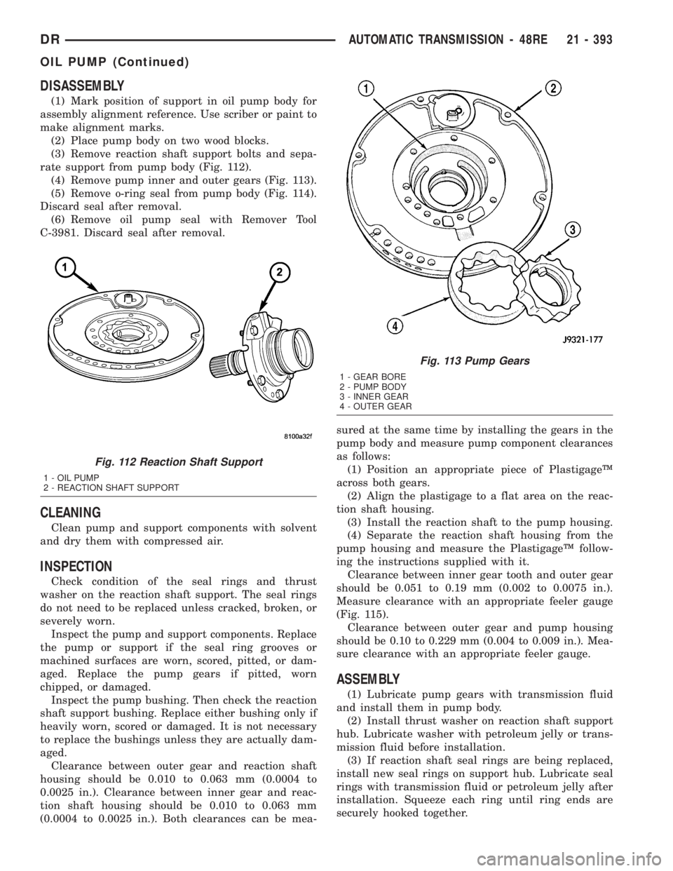
(3) Remove reaction shaft support bolts and sepa-
rate support from pump body (Fig. 112).
(4) Remove pump inner and outer gears (Fig. 113).
(5) Remove o-ring seal from pump body (Fig. 114).
Discard seal after removal.
(6) Remove oil pump seal with Remover Tool
C-3981. Discard seal after removal.
CLEANING
Clean pump and support components with solvent
and dry them with compressed air.
INSPECTION
Check condition of the seal rings and thrust
washer on the reaction shaft support. The seal rings
do not need to be replaced unless cracked, broken, or
severely worn.
Inspect the pump and support components. Replace
the pump or support if the seal ring grooves or
machined surfaces are worn, scored, pitted, or dam-
aged. Replace the pump gears if pitted, worn
chipped, or damaged.
Inspect the pump bushing. Then check the reaction
shaft support bushing. Replace either bushing only if
heavily worn, scored or damaged. It is not necessary
to replace the bushings unless they are actually dam-
aged.
Clearance between outer gear and reaction shaft
housing should be 0.010 to 0.063 mm (0.0004 to
0.0025 in.). Clearance between inner gear and reac-
tion shaft housing should be 0.010 to 0.063 mm
(0.0004 to 0.0025 in.). Both clearances can be mea-sured at the same time by installing the gears in the
pump body and measure pump component clearances
as follows:
(1) Position an appropriate piece of PlastigageŸ
across both gears.
(2) Align the plastigage to a flat area on the reac-
tion shaft housing.
(3) Install the reaction shaft to the pump housing.
(4) Separate the reaction shaft housing from the
pump housing and measure the PlastigageŸ follow-
ing the instructions supplied with it.
Clearance between inner gear tooth and outer gear
should be 0.051 to 0.19 mm (0.002 to 0.0075 in.).
Measure clearance with an appropriate feeler gauge
(Fig. 115).
Clearance between outer gear and pump housing
should be 0.10 to 0.229 mm (0.004 to 0.009 in.). Mea-
sure clearance with an appropriate feeler gauge.
ASSEMBLY
(1) Lubricate pump gears with transmission fluid
and install them in pump body.
(2) Install thrust washer on reaction shaft support
hub. Lubricate washer with petroleum jelly or trans-
mission fluid before installation.
(3) If reaction shaft seal rings are being replaced,
install new seal rings on support hub. Lubricate seal
rings with transmission fluid or petroleum jelly after
installation. Squeeze each ring until ring ends are
securely hooked together.
Fig. 112 Reaction Shaft Support
1 - OIL PUMP
2 - REACTION SHAFT SUPPORT
Fig. 113 Pump Gears
1 - GEAR BORE
2 - PUMP BODY
3 - INNER GEAR
4 - OUTER GEAR
DRAUTOMATIC TRANSMISSION - 48RE 21 - 393
OIL PUMP (Continued)
Page 2245 of 2895
able. Replace any of the overdrive unit snap-rings if
distorted or damaged.
Minor nicks or scratches on components can be
smoothed with crocus cloth. However, do not attempt
to reduce severe scoring on any components with
abrasive materials. Replace severely scored compo-
nents; do not try to salvage them.
INSPECTION
Check condition of the park lock components and
the overdrive case.
Check the bushings in the overdrive case. Replace
the bushings if severely scored or worn. Also replace
the case seal if loose, distorted, or damaged.
Examine the overdrive and direct clutch discs and
plates. Replace the discs if the facing is worn,
severely scored, or burned and flaking off. Replace
the clutch plates if worn, heavily scored, or cracked.
Check the lugs on the clutch plates for wear. The
plates should slide freely in the drum. Replace the
plates or drum if binding occurs.
Check condition of the annulus gear, direct clutch
hub, clutch drum and clutch spring. Replace the gear,
hub and drum if worn or damaged. Replace the
spring if collapsed, distorted, or cracked.
Be sure the splines and lugs on the gear, drum and
hub are in good condition. The clutch plates and
discs should slide freely in these components.
Inspect the thrust bearings and spring plate.
Replace the plate if worn or scored. Replace the bear-
ings if rough, noisy, brinnelled, or worn.
Inspect the planetary gear assembly and the sun
gear and bushings. If either the sun gear or the
bushings are damaged, replace the gear and bush-
ings as an assembly. The gear and bushings are not
serviced separately.
The planetary carrier and pinions must be in good
condition. Also be sure the pinion pins are secure and in
good condition. Replace the carrier if worn or damaged.
Inspect the overrunning clutch and race. The race
surface should be smooth and free of scores. Replace
the overrunning clutch assembly or the race if either
assembly is worn or damaged in any way.
Replace the shaft pilot bushing and inner bushing
if damaged. Replace either shaft bearing if rough or
noisy. Replace the bearing snap-rings if distorted or
cracked.
Check the machined surfaces on the output shaft.
These surfaces should clean and smooth. Very minor
nicks or scratches can be smoothed with crocus cloth.
Replace the shaft if worn, scored or damaged in any way.
Inspect the output shaft bushings. The small bush-
ing is the intermediate shaft pilot bushing. The large
bushing is the overrunning clutch hub bushing.
Replace either bushing if scored, pitted, cracked, or
worn.
ASSEMBLY
GEARTRAIN AND DIRECT CLUTCH
(1) Soak direct clutch and overdrive clutch discs in
MopartATF +4, Automatic Transmission fluid. Allow
discs to soak for 10-20 minutes.
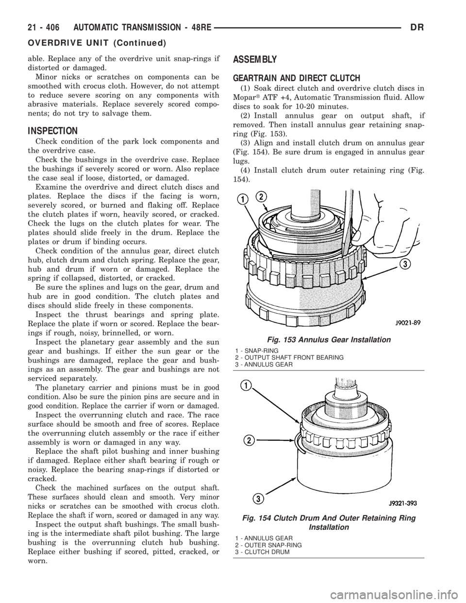
(2) Install annulus gear on output shaft, if
removed. Then install annulus gear retaining snap-
ring (Fig. 153).
(3) Align and install clutch drum on annulus gear
(Fig. 154). Be sure drum is engaged in annulus gear
lugs.
(4) Install clutch drum outer retaining ring (Fig.
154).
Fig. 153 Annulus Gear Installation
1 - SNAP-RING
2 - OUTPUT SHAFT FRONT BEARING
3 - ANNULUS GEAR
Fig. 154 Clutch Drum And Outer Retaining Ring
Installation
1 - ANNULUS GEAR
2 - OUTER SNAP-RING
3 - CLUTCH DRUM
21 - 406 AUTOMATIC TRANSMISSION - 48REDR
OVERDRIVE UNIT (Continued)
Page 2251 of 2895
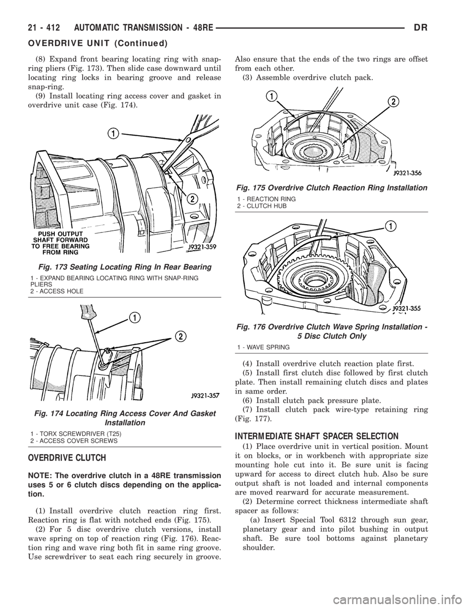
(8) Expand front bearing locating ring with snap-
ring pliers (Fig. 173). Then slide case downward until
locating ring locks in bearing groove and release
snap-ring.
(9) Install locating ring access cover and gasket in
overdrive unit case (Fig. 174).
OVERDRIVE CLUTCH
NOTE: The overdrive clutch in a 48RE transmission
uses 5 or 6 clutch discs depending on the applica-
tion.
(1) Install overdrive clutch reaction ring first.
Reaction ring is flat with notched ends (Fig. 175).
(2) For 5 disc overdrive clutch versions, install
wave spring on top of reaction ring (Fig. 176). Reac-
tion ring and wave ring both fit in same ring groove.
Use screwdriver to seat each ring securely in groove.Also ensure that the ends of the two rings are offset
from each other.
(3) Assemble overdrive clutch pack.
(4) Install overdrive clutch reaction plate first.
(5) Install first clutch disc followed by first clutch
plate. Then install remaining clutch discs and plates
in same order.
(6) Install clutch pack pressure plate.
(7) Install clutch pack wire-type retaining ring
(Fig. 177).
INTERMEDIATE SHAFT SPACER SELECTION
(1) Place overdrive unit in vertical position. Mount
it on blocks, or in workbench with appropriate size
mounting hole cut into it. Be sure unit is facing
upward for access to direct clutch hub. Also be sure
output shaft is not loaded and internal components
are moved rearward for accurate measurement.
(2) Determine correct thickness intermediate shaft
spacer as follows:
(a) Insert Special Tool 6312 through sun gear,
planetary gear and into pilot bushing in output
shaft. Be sure tool bottoms against planetary
shoulder.
Fig. 173 Seating Locating Ring In Rear Bearing
1 - EXPAND BEARING LOCATING RING WITH SNAP-RING
PLIERS
2 - ACCESS HOLE
Fig. 174 Locating Ring Access Cover And Gasket
Installation
1 - TORX SCREWDRIVER (T25)
2 - ACCESS COVER SCREWS
Fig. 175 Overdrive Clutch Reaction Ring Installation
1 - REACTION RING
2 - CLUTCH HUB
Fig. 176 Overdrive Clutch Wave Spring Installation -
5 Disc Clutch Only
1 - WAVE SPRING
21 - 412 AUTOMATIC TRANSMISSION - 48REDR
OVERDRIVE UNIT (Continued)
Page 2260 of 2895
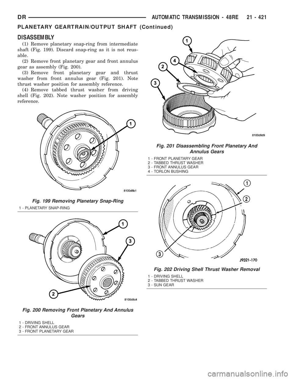
DISASSEMBLY
(1) Remove planetary snap-ring from intermediate
shaft (Fig. 199). Discard snap-ring as it is not reus-
able.
(2) Remove front planetary gear and front annulus
gear as assembly (Fig. 200).
(3) Remove front planetary gear and thrust
washer from front annulus gear (Fig. 201). Note
thrust washer position for assembly reference.
(4) Remove tabbed thrust washer from driving
shell (Fig. 202). Note washer position for assembly
reference.
Fig. 199 Removing Planetary Snap-Ring
1 - PLANETARY SNAP-RING
Fig. 200 Removing Front Planetary And Annulus
Gears
1 - DRIVING SHELL
2 - FRONT ANNULUS GEAR
3 - FRONT PLANETARY GEAR
Fig. 201 Disassembling Front Planetary And
Annulus Gears
1 - FRONT PLANETARY GEAR
2 - TABBED THRUST WASHER
3 - FRONT ANNULUS GEAR
4 - TORLON BUSHING
Fig. 202 Driving Shell Thrust Washer Removal
1 - DRIVING SHELL
2 - TABBED THRUST WASHER
3 - SUN GEAR
DRAUTOMATIC TRANSMISSION - 48RE 21 - 421
PLANETARY GEARTRAIN/OUTPUT SHAFT (Continued)