bushing DODGE RAM 2003 Service Manual PDF
[x] Cancel search | Manufacturer: DODGE, Model Year: 2003, Model line: RAM, Model: DODGE RAM 2003Pages: 2895, PDF Size: 83.15 MB
Page 1954 of 2895
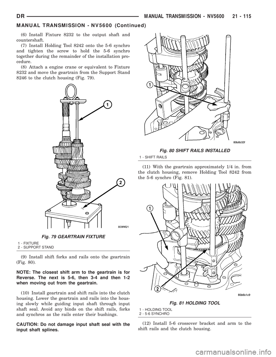
(6) Install Fixture 8232 to the output shaft and
countershaft.
(7) Install Holding Tool 8242 onto the 5-6 synchro
and tighten the screw to hold the 5-6 synchro
together during the remainder of the installation pro-
cedure.
(8) Attach a engine crane or equivalent to Fixture
8232 and move the geartrain from the Support Stand
8246 to the clutch housing (Fig. 79).
(9) Install shift forks and rails onto the geartrain
(Fig. 80).
NOTE: The closest shift arm to the geartrain is for
Reverse. The next is 5-6, then 3-4 and then 1-2
when moving out from the geartrain.
(10) Install geartrain and shift rails into the clutch
housing. Lower the geartrain and rails into the hous-
ing slowly while guiding input shaft through input
shaft seal. Avoid any binds on the shift rails, forks
and synchros as the rails enter their bushings.
CAUTION: Do not damage input shaft seal with the
input shaft splines.(11) With the geartrain approximately 1/4 in. from
the clutch housing, remove Holding Tool 8242 from
the 5-6 synchro (Fig. 81).
(12) Install 5-6 crossover bracket and arm to the
shift rails and the clutch housing.
Fig. 79 GEARTRAIN FIXTURE
1 - FIXTURE
2 - SUPPORT STAND
Fig. 80 SHIFT RAILS INSTALLED
1 - SHIFT RAILS
Fig. 81 HOLDING TOOL
1 - HOLDING TOOL
2 - 5-6 SYNCHRO
DRMANUAL TRANSMISSION - NV5600 21 - 115
MANUAL TRANSMISSION - NV5600 (Continued)
Page 1958 of 2895
(13) Install reverse idler thrust washer from the
reverse idler.
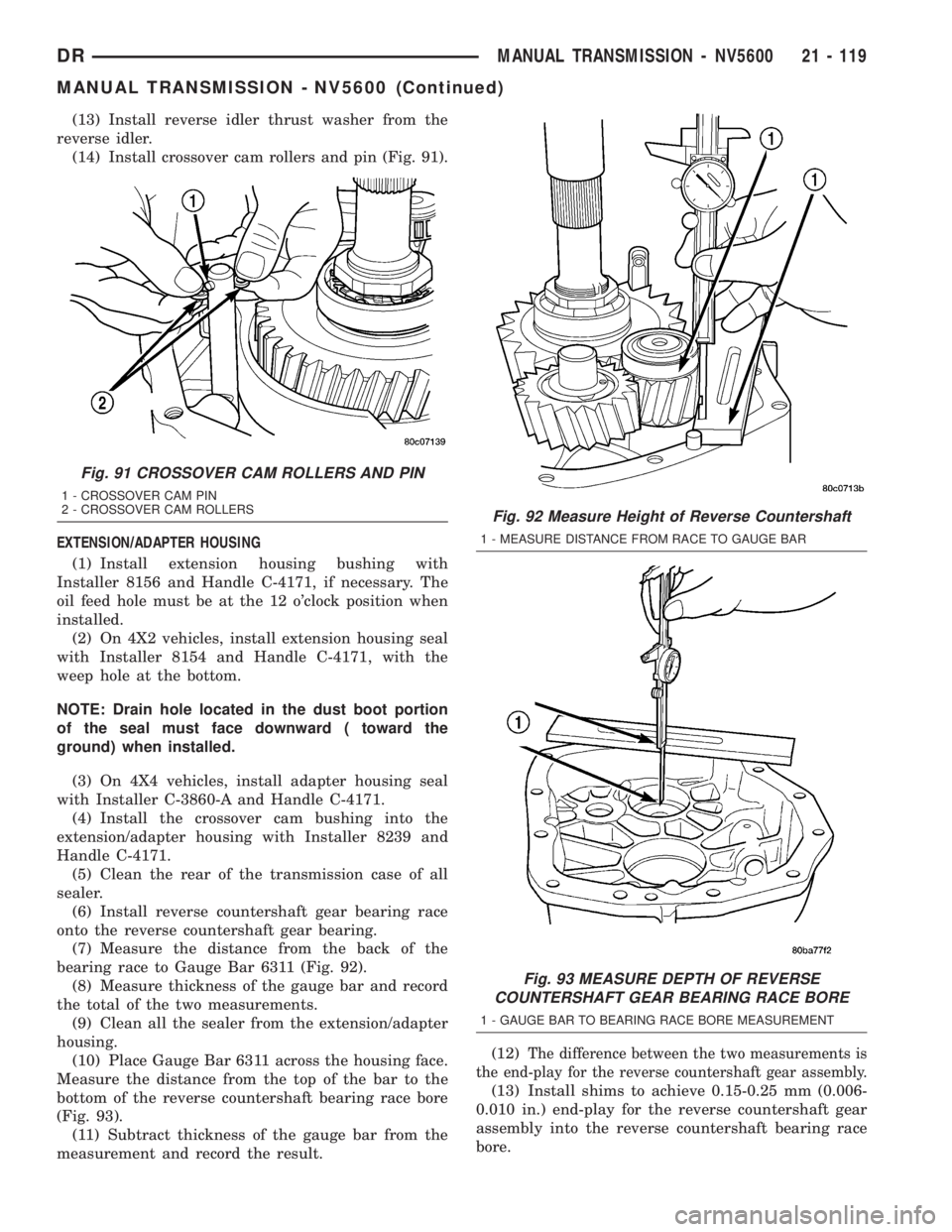
(14) Install crossover cam rollers and pin (Fig. 91).
EXTENSION/ADAPTER HOUSING
(1) Install extension housing bushing with
Installer 8156 and Handle C-4171, if necessary. The
oil feed hole must be at the 12 o'clock position when
installed.
(2) On 4X2 vehicles, install extension housing seal
with Installer 8154 and Handle C-4171, with the
weep hole at the bottom.
NOTE: Drain hole located in the dust boot portion
of the seal must face downward ( toward the
ground) when installed.
(3) On 4X4 vehicles, install adapter housing seal
with Installer C-3860-A and Handle C-4171.
(4) Install the crossover cam bushing into the
extension/adapter housing with Installer 8239 and
Handle C-4171.
(5) Clean the rear of the transmission case of all
sealer.
(6) Install reverse countershaft gear bearing race
onto the reverse countershaft gear bearing.
(7) Measure the distance from the back of the
bearing race to Gauge Bar 6311 (Fig. 92).
(8) Measure thickness of the gauge bar and record
the total of the two measurements.
(9) Clean all the sealer from the extension/adapter
housing.
(10) Place Gauge Bar 6311 across the housing face.
Measure the distance from the top of the bar to the
bottom of the reverse countershaft bearing race bore
(Fig. 93).
(11) Subtract thickness of the gauge bar from the
measurement and record the result.(12)
The difference between the two measurements is
the end-play for the reverse countershaft gear assembly.
(13) Install shims to achieve 0.15-0.25 mm (0.006-
0.010 in.) end-play for the reverse countershaft gear
assembly into the reverse countershaft bearing race
bore.
Fig. 91 CROSSOVER CAM ROLLERS AND PIN
1 - CROSSOVER CAM PIN
2 - CROSSOVER CAM ROLLERS
Fig. 92 Measure Height of Reverse Countershaft
1 - MEASURE DISTANCE FROM RACE TO GAUGE BAR
Fig. 93 MEASURE DEPTH OF REVERSE
COUNTERSHAFT GEAR BEARING RACE BORE
1 - GAUGE BAR TO BEARING RACE BORE MEASUREMENT
DRMANUAL TRANSMISSION - NV5600 21 - 119
MANUAL TRANSMISSION - NV5600 (Continued)
Page 1959 of 2895
(14) Use Installer to install the reverse counter-
shaft bearing race into the extension/adapter hous-
ing.
(15) Install back-up lamp switch into the exten-
sion/adapter housing and tighten to 28 N´m (20
ft.lbs.).
(16) Install crossover cam into the extension/
adapter housing.
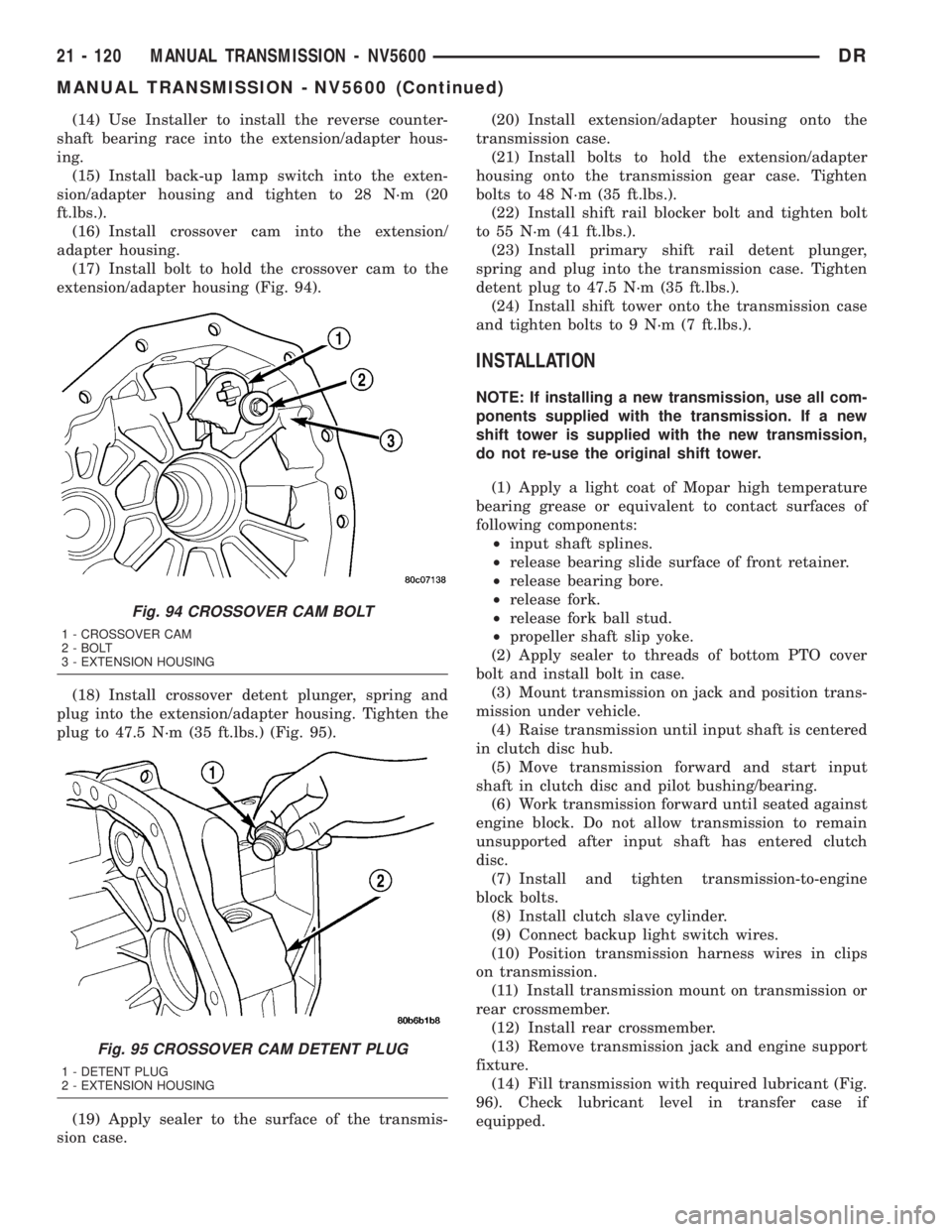
(17) Install bolt to hold the crossover cam to the
extension/adapter housing (Fig. 94).
(18) Install crossover detent plunger, spring and
plug into the extension/adapter housing. Tighten the
plug to 47.5 N´m (35 ft.lbs.) (Fig. 95).
(19) Apply sealer to the surface of the transmis-
sion case.(20) Install extension/adapter housing onto the
transmission case.
(21) Install bolts to hold the extension/adapter
housing onto the transmission gear case. Tighten
bolts to 48 N´m (35 ft.lbs.).
(22) Install shift rail blocker bolt and tighten bolt
to 55 N´m (41 ft.lbs.).
(23) Install primary shift rail detent plunger,
spring and plug into the transmission case. Tighten
detent plug to 47.5 N´m (35 ft.lbs.).
(24) Install shift tower onto the transmission case
and tighten bolts to 9 N´m (7 ft.lbs.).
INSTALLATION
NOTE: If installing a new transmission, use all com-
ponents supplied with the transmission. If a new
shift tower is supplied with the new transmission,
do not re-use the original shift tower.
(1) Apply a light coat of Mopar high temperature
bearing grease or equivalent to contact surfaces of
following components:
²input shaft splines.
²release bearing slide surface of front retainer.
²release bearing bore.
²release fork.
²release fork ball stud.
²propeller shaft slip yoke.
(2) Apply sealer to threads of bottom PTO cover
bolt and install bolt in case.
(3) Mount transmission on jack and position trans-
mission under vehicle.
(4) Raise transmission until input shaft is centered
in clutch disc hub.
(5) Move transmission forward and start input
shaft in clutch disc and pilot bushing/bearing.
(6) Work transmission forward until seated against
engine block. Do not allow transmission to remain
unsupported after input shaft has entered clutch
disc.
(7) Install and tighten transmission-to-engine
block bolts.
(8) Install clutch slave cylinder.
(9) Connect backup light switch wires.
(10) Position transmission harness wires in clips
on transmission.
(11) Install transmission mount on transmission or
rear crossmember.
(12) Install rear crossmember.
(13) Remove transmission jack and engine support
fixture.
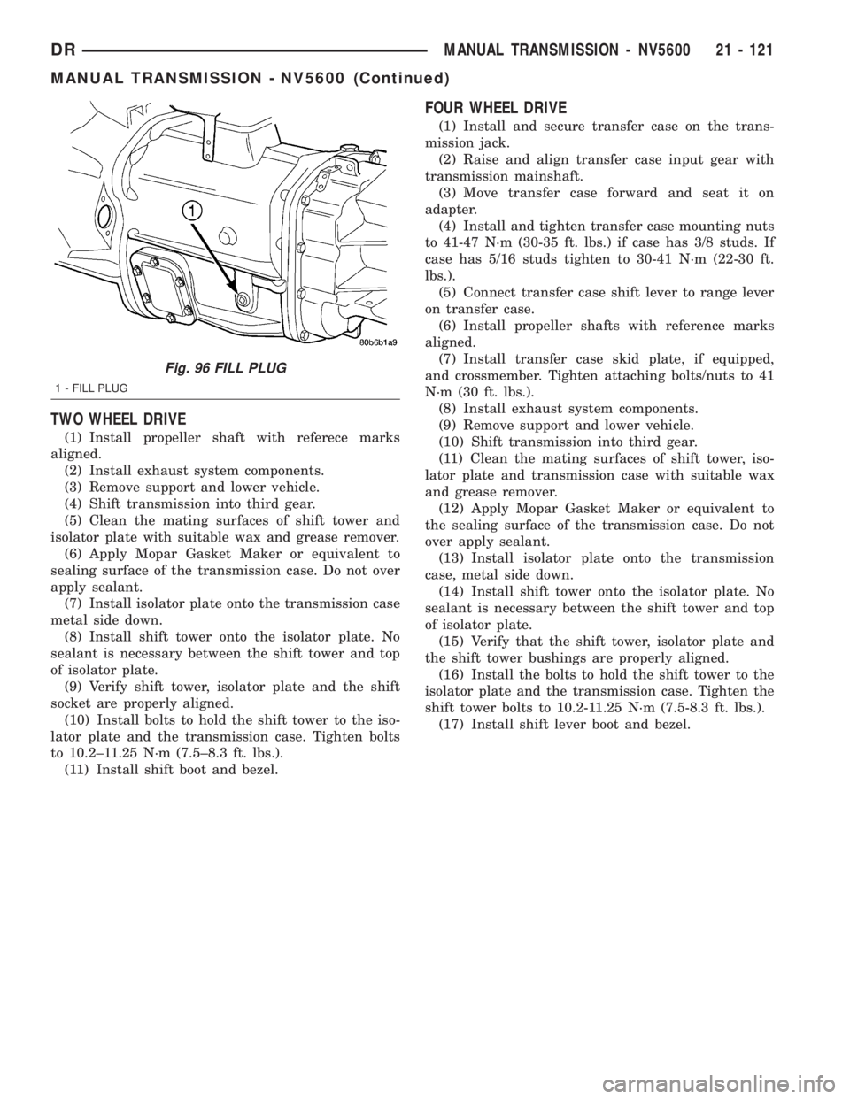
(14) Fill transmission with required lubricant (Fig.
96). Check lubricant level in transfer case if
equipped.
Fig. 94 CROSSOVER CAM BOLT
1 - CROSSOVER CAM
2 - BOLT
3 - EXTENSION HOUSING
Fig. 95 CROSSOVER CAM DETENT PLUG
1 - DETENT PLUG
2 - EXTENSION HOUSING
21 - 120 MANUAL TRANSMISSION - NV5600DR
MANUAL TRANSMISSION - NV5600 (Continued)
Page 1960 of 2895
TWO WHEEL DRIVE
(1) Install propeller shaft with referece marks
aligned.
(2) Install exhaust system components.
(3) Remove support and lower vehicle.
(4) Shift transmission into third gear.
(5) Clean the mating surfaces of shift tower and
isolator plate with suitable wax and grease remover.
(6) Apply Mopar Gasket Maker or equivalent to
sealing surface of the transmission case. Do not over
apply sealant.
(7) Install isolator plate onto the transmission case
metal side down.
(8) Install shift tower onto the isolator plate. No
sealant is necessary between the shift tower and top
of isolator plate.
(9) Verify shift tower, isolator plate and the shift
socket are properly aligned.
(10) Install bolts to hold the shift tower to the iso-
lator plate and the transmission case. Tighten bolts
to 10.2±11.25 N´m (7.5±8.3 ft. lbs.).
(11) Install shift boot and bezel.
FOUR WHEEL DRIVE
(1) Install and secure transfer case on the trans-
mission jack.
(2) Raise and align transfer case input gear with
transmission mainshaft.
(3) Move transfer case forward and seat it on
adapter.
(4) Install and tighten transfer case mounting nuts
to 41-47 N´m (30-35 ft. lbs.) if case has 3/8 studs. If
case has 5/16 studs tighten to 30-41 N´m (22-30 ft.
lbs.).
(5) Connect transfer case shift lever to range lever
on transfer case.
(6) Install propeller shafts with reference marks
aligned.
(7) Install transfer case skid plate, if equipped,
and crossmember. Tighten attaching bolts/nuts to 41
N´m (30 ft. lbs.).
(8) Install exhaust system components.
(9) Remove support and lower vehicle.
(10) Shift transmission into third gear.
(11) Clean the mating surfaces of shift tower, iso-
lator plate and transmission case with suitable wax
and grease remover.
(12) Apply Mopar Gasket Maker or equivalent to
the sealing surface of the transmission case. Do not
over apply sealant.
(13) Install isolator plate onto the transmission
case, metal side down.
(14) Install shift tower onto the isolator plate. No
sealant is necessary between the shift tower and top
of isolator plate.
(15) Verify that the shift tower, isolator plate and
the shift tower bushings are properly aligned.
(16) Install the bolts to hold the shift tower to the
isolator plate and the transmission case. Tighten the
shift tower bolts to 10.2-11.25 N´m (7.5-8.3 ft. lbs.).
(17) Install shift lever boot and bezel.
Fig. 96 FILL PLUG
1 - FILL PLUG
DRMANUAL TRANSMISSION - NV5600 21 - 121
MANUAL TRANSMISSION - NV5600 (Continued)
Page 1966 of 2895
ADAPTER HOUSING SEAL
REMOVAL
(1) Raise and support vehicle.
(2) Mark propeller shaft and yokes for installation
reference and remove shaft.
(3) Remove the transfer case.
(4) Remove the adapter housing seal with a pry
tool or slide hammer with a screw.
INSTALLATION
(1) Install adapter housing seal with Installer and
Handle C-4171.
(2) Install transfer case.
(3) Install propeller shaft with reference marks
aligned.
(4) Check fluid level.
(5) Remove support and lower vehicle.
EXTENSION HOUSING SEAL
REMOVAL
(1) Mark propeller shaft and pinion yoke for
installation reference and remove the propeller shaft.
(2) Remove extension housing seal with a pry tool
or a slide hammer and screw.
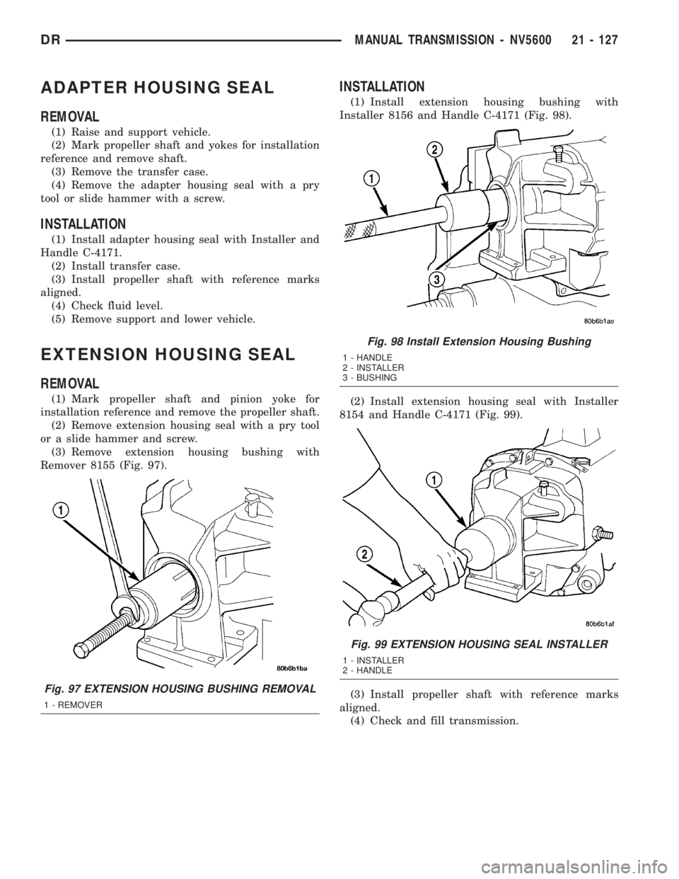
(3) Remove extension housing bushing with
Remover 8155 (Fig. 97).
INSTALLATION
(1) Install extension housing bushing with
Installer 8156 and Handle C-4171 (Fig. 98).
(2) Install extension housing seal with Installer
8154 and Handle C-4171 (Fig. 99).
(3) Install propeller shaft with reference marks
aligned.
(4) Check and fill transmission.
Fig. 97 EXTENSION HOUSING BUSHING REMOVAL
1 - REMOVER
Fig. 98 Install Extension Housing Bushing
1 - HANDLE
2 - INSTALLER
3 - BUSHING
Fig. 99 EXTENSION HOUSING SEAL INSTALLER
1 - INSTALLER
2 - HANDLE
DRMANUAL TRANSMISSION - NV5600 21 - 127
Page 1967 of 2895
SHIFT COVER
REMOVAL
(1) Shift transmission into Neutral.
(2) Unscrew and remove the shift lever extension
from the shift
(3) Remove screws attaching shift boot to floorpan.
Then slide boot upward on the shift lever.
(4) Remove the bolts holding the shift tower to the
isolator plate and transmission gear case.
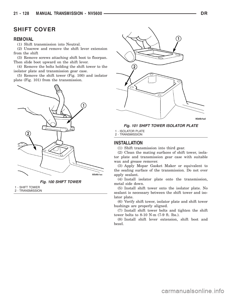
(5) Remove the shift tower (Fig. 100) and isolator
plate (Fig. 101) from the transmission.
INSTALLATION
(1) Shift transmission into third gear.
(2) Clean the mating surfaces of shift tower, isola-
tor plate and transmission gear case with suitable
wax and grease remover.
(3) Apply Mopar Gasket Maker or equivalent to
the sealing surface of the transmission. Do not over
apply sealant.
(4) Install isolator plate onto the transmission,
metal side down.
(5) Install shift tower onto the isolator plate. No
sealant is necessary between the shift tower and iso-
lator plate.
(6) Verify shift tower, isolator plate and shift tower
bushings are properly aligned.
(7) Install shift tower bolts and tighten the shift
tower bolts to 8-10 N´m (7-9 ft. lbs.).
(8) Install shift lever extension, shift boot and
bezel.
Fig. 100 SHIFT TOWER
1 - SHIFT TOWER
2 - TRANSMISSION
Fig. 101 SHIFT TOWER ISOLATOR PLATE
1 - ISOLATOR PLATE
2 - TRANSMISSION
21 - 128 MANUAL TRANSMISSION - NV5600DR
Page 1968 of 2895
AUTOMATIC TRANSMISSION - 46RE
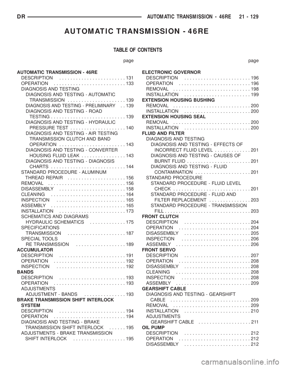
TABLE OF CONTENTS
page page
AUTOMATIC TRANSMISSION - 46RE
DESCRIPTION........................131
OPERATION..........................133
DIAGNOSIS AND TESTING
DIAGNOSIS AND TESTING - AUTOMATIC
TRANSMISSION.....................139
DIAGNOSIS AND TESTING - PRELIMINARY. . 139
DIAGNOSIS AND TESTING - ROAD
TESTING...........................139
DIAGNOSIS AND TESTING - HYDRAULIC
PRESSURE TEST....................140
DIAGNOSIS AND TESTING - AIR TESTING
TRANSMISSION CLUTCH AND BAND
OPERATION........................143
DIAGNOSIS AND TESTING - CONVERTER
HOUSING FLUID LEAK................143
DIAGNOSIS AND TESTING - DIAGNOSIS
CHARTS...........................144
STANDARD PROCEDURE - ALUMINUM
THREAD REPAIR.....................156
REMOVAL............................156
DISASSEMBLY........................158
CLEANING...........................164
INSPECTION.........................165
ASSEMBLY...........................165
INSTALLATION........................173
SCHEMATICS AND DIAGRAMS
HYDRAULIC SCHEMATICS.............175
SPECIFICATIONS
TRANSMISSION.....................187
SPECIAL TOOLS
RE TRANSMISSION..................189
ACCUMULATOR
DESCRIPTION........................191
OPERATION..........................192
INSPECTION.........................192
BANDS
DESCRIPTION........................193
OPERATION..........................193
ADJUSTMENTS
ADJUSTMENT - BANDS...............193
BRAKE TRANSMISSION SHIFT INTERLOCK
SYSTEM
DESCRIPTION........................194
OPERATION..........................194
DIAGNOSIS AND TESTING - BRAKE
TRANSMISSION SHIFT INTERLOCK......195
ADJUSTMENTS - BRAKE TRANSMISSION
SHIFT INTERLOCK...................195ELECTRONIC GOVERNOR
DESCRIPTION........................196
OPERATION..........................196
REMOVAL............................198
INSTALLATION........................199
EXTENSION HOUSING BUSHING
REMOVAL............................200
INSTALLATION........................200
EXTENSION HOUSING SEAL
REMOVAL............................200
INSTALLATION........................200
FLUID AND FILTER
DIAGNOSIS AND TESTING
DIAGNOSIS AND TESTING - EFFECTS OF
INCORRECT FLUID LEVEL.............201
DIAGNOSIS AND TESTING - CAUSES OF
BURNT FLUID.......................201
DIAGNOSIS AND TESTING - FLUID
CONTAMINATION....................201
STANDARD PROCEDURE
STANDARD PROCEDURE - FLUID LEVEL
CHECK............................201
STANDARD PROCEDURE - FLUID AND
FILTER REPLACEMENT...............203
STANDARD PROCEDURE - TRANSMISSION
FILL...............................203
FRONT CLUTCH
DESCRIPTION........................204
OPERATION..........................204
DISASSEMBLY........................205
INSPECTION.........................206
ASSEMBLY...........................206
FRONT SERVO
DESCRIPTION........................207
OPERATION..........................208
DISASSEMBLY........................208
CLEANING...........................208
INSPECTION.........................208
ASSEMBLY...........................209
GEARSHIFT CABLE
DIAGNOSIS AND TESTING - GEARSHIFT
CABLE.............................209
REMOVAL............................209
INSTALLATION........................210
ADJUSTMENTS
GEARSHIFT CABLE...................211
OIL PUMP
DESCRIPTION........................212
OPERATION..........................212
DISASSEMBLY........................212
DRAUTOMATIC TRANSMISSION - 46RE 21 - 129
Page 1981 of 2895
Test Four - Transmission In Reverse
This test checks pump output, pressure regulation
and the front clutch and rear servo circuits. Use 300
psi Test Gauge C-3293-SP for this test.
(1) Leave vehicle on hoist and leave gauge C-3292
in place at accumulator port.
(2) Move 300 psi Gauge C-3293-SP back to rear
servo port.
(3) Have helper start and run engine at 1600 rpm
for test.
(4) Move transmission shift lever four detents
rearward from full forward position. This is Reverse
range.
(5) Move transmission throttle lever fully forward
then fully rearward and note reading at Gauge
C-3293-SP.
(6) Pressure should be 145 - 175 psi (1000-1207
kPa) with throttle lever forward and increase to 230 -
280 psi (1586-1931 kPa) as lever is gradually moved
rearward.
Test Five - Governor Pressure
This test checks governor operation by measuring
governor pressure response to changes in vehicle
speed. It is usually not necessary to check governor
operation unless shift speeds are incorrect or if the
transmission will not downshift. The test should be
performed on the road or on a hoist that will allow
the rear wheels to rotate freely.
(1) Move 100 psi Test Gauge C-3292 to governor
pressure port.
(2) Move transmission shift lever two detents rear-
ward from full forward position. This is D range.
(3) Have helper start and run engine at curb idle
speed. Then firmly apply service brakes so wheels
will not rotate.
(4) Note governor pressure:
²Governor pressure should be no more than 20.6
kPa (3 psi) at curb idle speed and wheels not rotat-
ing.
²If pressure exceeds 20.6 kPa (3 psi), a fault
exists in governor pressure control system.
(5) Release brakes, slowly increase engine speed,
and observe speedometer and pressure test gauge (do
not exceed 30 mph on speedometer). Governor pres-
sure should increase in proportion to vehicle speed.
Or approximately 6.89 kPa (1 psi) for every 1 mph.
(6) Governor pressure rise should be smooth and
drop back to no more than 20.6 kPa (3 psi), after
engine returns to curb idle and brakes are applied to
prevent wheels from rotating.
(7) Compare results of pressure test with analysis
chart.Test Six - Transmission In Overdrive Fourth Gear
This test checks line pressure at the overdrive
clutch in fourth gear range. Use 300 psi Test Gauge
C-3293-SP for this test. The test should be performed
on the road or on a chassis dyno.
(1) Remove tachometer; it is not needed for this
test.
(2) Move 300 psi Gauge to overdrive clutch pres-
sure test port. Then remove other gauge and reinstall
test port plug.
(3) Lower vehicle.
(4) Turn OD switch on.
(5) Secure test gauge so it can be viewed from
drivers seat.
(6) Start engine and shift into D range.
(7) Increase vehicle speed gradually until 3-4 shift
occurs and note gauge pressure.
(8) Pressure should be 469-496 kPa (68-72 psi)
with closed throttle and increase to 620-827 kPa (90-
120 psi) at 1/2 to 3/4 throttle. Note that pressure can
increase to around 896 kPa (130 psi) at full throttle.
(9) Return to shop or move vehicle off chassis
dyno.
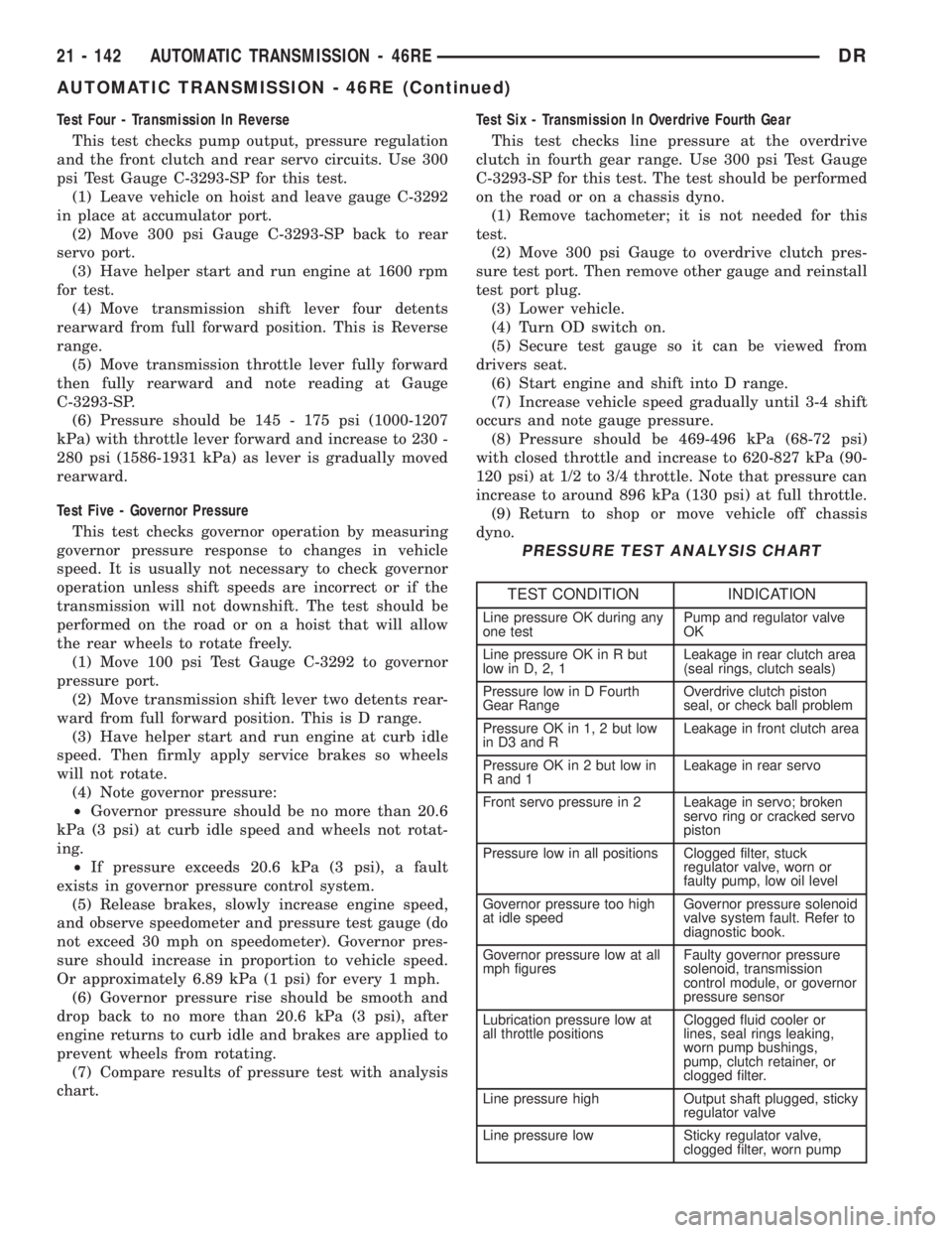
PRESSURE TEST ANALYSIS CHART
TEST CONDITION INDICATION
Line pressure OK during any
one testPump and regulator valve
OK
Line pressure OK in R but
low in D, 2, 1Leakage in rear clutch area
(seal rings, clutch seals)
Pressure low in D Fourth
Gear RangeOverdrive clutch piston
seal, or check ball problem
Pressure OK in 1, 2 but low
in D3 and RLeakage in front clutch area
Pressure OK in 2 but low in
R and 1Leakage in rear servo
Front servo pressure in 2 Leakage in servo; broken
servo ring or cracked servo
piston
Pressure low in all positions Clogged filter, stuck
regulator valve, worn or
faulty pump, low oil level
Governor pressure too high
at idle speedGovernor pressure solenoid
valve system fault. Refer to
diagnostic book.
Governor pressure low at all
mph figuresFaulty governor pressure
solenoid, transmission
control module, or governor
pressure sensor
Lubrication pressure low at
all throttle positionsClogged fluid cooler or
lines, seal rings leaking,
worn pump bushings,
pump, clutch retainer, or
clogged filter.
Line pressure high Output shaft plugged, sticky
regulator valve
Line pressure low Sticky regulator valve,
clogged filter, worn pump
21 - 142 AUTOMATIC TRANSMISSION - 46REDR
AUTOMATIC TRANSMISSION - 46RE (Continued)
Page 1983 of 2895
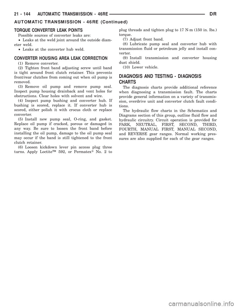
TORQUE CONVERTER LEAK POINTS
Possible sources of converter leaks are:
²Leaks at the weld joint around the outside diam-
eter weld.
²Leaks at the converter hub weld.
CONVERTER HOUSING AREA LEAK CORRECTION
(1) Remove converter.
(2) Tighten front band adjusting screw until band
is tight around front clutch retainer. This prevents
front/rear clutches from coming out when oil pump is
removed.
(3) Remove oil pump and remove pump seal.
Inspect pump housing drainback and vent holes for
obstructions. Clear holes with solvent and wire.
(4) Inspect pump bushing and converter hub. If
bushing is scored, replace it. If converter hub is
scored, either polish it with crocus cloth or replace
converter.
(5) Install new pump seal, O-ring, and gasket.
Replace oil pump if cracked, porous or damaged in
any way. Be sure to loosen the front band before
installing the oil pump, damage to the oil pump seal
may occur if the band is still tightened to the front
clutch retainer.
(6) Loosen kickdown lever pin access plug three
turns. Apply LoctiteŸ 592, or PermatextNo.2toplug threads and tighten plug to 17 N´m (150 in. lbs.)
torque.
(7) Adjust front band.
(8) Lubricate pump seal and converter hub with
transmission fluid or petroleum jelly and install con-
verter.
(9) Install transmission and converter housing
dust shield.
(10) Lower vehicle.
DIAGNOSIS AND TESTING - DIAGNOSIS
CHARTS
The diagnosis charts provide additional reference
when diagnosing a transmission fault. The charts
provide general information on a variety of transmis-
sion, overdrive unit and converter clutch fault condi-
tions.
The hydraulic flow charts in the Schematics and
Diagrams section of this group, outline fluid flow and
hydraulic circuitry. Circuit operation is provided for
PARK, NEUTRAL, FIRST, SECOND, THIRD,
FOURTH, MANUAL FIRST, MANUAL SECOND,
and REVERSE gear ranges. Normal working pres-
sures are also supplied for each of the gear ranges.
21 - 144 AUTOMATIC TRANSMISSION - 46REDR
AUTOMATIC TRANSMISSION - 46RE (Continued)
Page 1984 of 2895
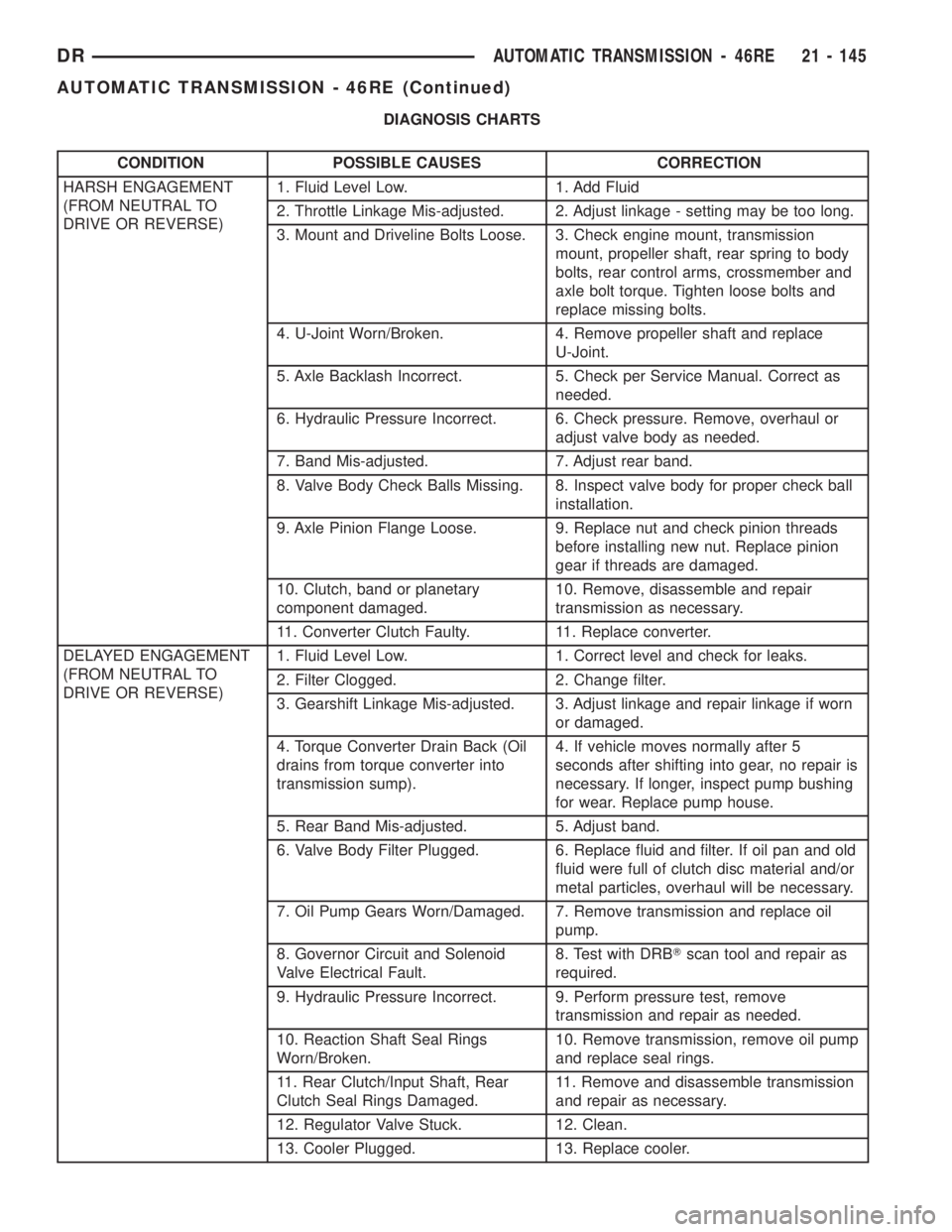
DIAGNOSIS CHARTS
CONDITION POSSIBLE CAUSES CORRECTION
HARSH ENGAGEMENT
(FROM NEUTRAL TO
DRIVE OR REVERSE)1. Fluid Level Low. 1. Add Fluid
2. Throttle Linkage Mis-adjusted. 2. Adjust linkage - setting may be too long.
3. Mount and Driveline Bolts Loose. 3. Check engine mount, transmission
mount, propeller shaft, rear spring to body
bolts, rear control arms, crossmember and
axle bolt torque. Tighten loose bolts and
replace missing bolts.
4. U-Joint Worn/Broken. 4. Remove propeller shaft and replace
U-Joint.
5. Axle Backlash Incorrect. 5. Check per Service Manual. Correct as
needed.
6. Hydraulic Pressure Incorrect. 6. Check pressure. Remove, overhaul or
adjust valve body as needed.
7. Band Mis-adjusted. 7. Adjust rear band.
8. Valve Body Check Balls Missing. 8. Inspect valve body for proper check ball
installation.
9. Axle Pinion Flange Loose. 9. Replace nut and check pinion threads
before installing new nut. Replace pinion
gear if threads are damaged.
10. Clutch, band or planetary
component damaged.10. Remove, disassemble and repair
transmission as necessary.
11. Converter Clutch Faulty. 11. Replace converter.
DELAYED ENGAGEMENT
(FROM NEUTRAL TO
DRIVE OR REVERSE)1. Fluid Level Low. 1. Correct level and check for leaks.
2. Filter Clogged. 2. Change filter.
3. Gearshift Linkage Mis-adjusted. 3. Adjust linkage and repair linkage if worn
or damaged.
4. Torque Converter Drain Back (Oil
drains from torque converter into
transmission sump).4. If vehicle moves normally after 5
seconds after shifting into gear, no repair is
necessary. If longer, inspect pump bushing
for wear. Replace pump house.
5. Rear Band Mis-adjusted. 5. Adjust band.
6. Valve Body Filter Plugged. 6. Replace fluid and filter. If oil pan and old
fluid were full of clutch disc material and/or
metal particles, overhaul will be necessary.
7. Oil Pump Gears Worn/Damaged. 7. Remove transmission and replace oil
pump.
8. Governor Circuit and Solenoid
Valve Electrical Fault.8. Test with DRBTscan tool and repair as
required.
9. Hydraulic Pressure Incorrect. 9. Perform pressure test, remove
transmission and repair as needed.
10. Reaction Shaft Seal Rings
Worn/Broken.10. Remove transmission, remove oil pump
and replace seal rings.
11. Rear Clutch/Input Shaft, Rear
Clutch Seal Rings Damaged.11. Remove and disassemble transmission
and repair as necessary.
12. Regulator Valve Stuck. 12. Clean.
13. Cooler Plugged. 13. Replace cooler.
DRAUTOMATIC TRANSMISSION - 46RE 21 - 145
AUTOMATIC TRANSMISSION - 46RE (Continued)