DODGE RAM 2003 Service Repair Manual
Manufacturer: DODGE, Model Year: 2003, Model line: RAM, Model: DODGE RAM 2003Pages: 2895, PDF Size: 83.15 MB
Page 1241 of 2895
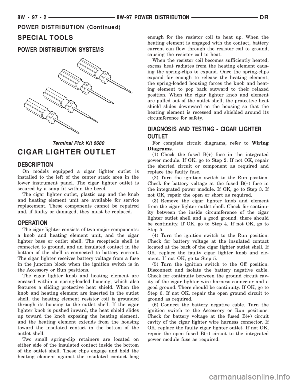
SPECIAL TOOLS
POWER DISTRIBUTION SYSTEMS
CIGAR LIGHTER OUTLET
DESCRIPTION
On models equipped a cigar lighter outlet is
installed to the left of the center stack area in the
lower instrument panel. The cigar lighter outlet is
secured by a snap fit within the bezel.
The cigar lighter outlet, plastic cap and the knob
and heating element unit are available for service
replacement. These components cannot be repaired
and, if faulty or damaged, they must be replaced.
OPERATION
The cigar lighter consists of two major components:
a knob and heating element unit, and the cigar
lighter base or outlet shell. The receptacle shell is
connected to ground, and an insulated contact in the
bottom of the shell is connected to battery current.
The cigar lighter receives battery voltage from a fuse
in the junction block when the ignition switch is in
the Accessory or Run positions.
The cigar lighter knob and heating element are
encased within a spring-loaded housing, which also
features a sliding protective heat shield. When the
knob and heating element are inserted in the outlet
shell, the heating element resistor coil is grounded
through its housing to the outlet shell. If the cigar
lighter knob is pushed inward, the heat shield slides
up toward the knob exposing the heating element,
and the heating element extends from the housing
toward the insulated contact in the bottom of the
outlet shell.
Two small spring-clip retainers are located on
either side of the insulated contact inside the bottom
of the outlet shell. These clips engage and hold the
heating element against the insulated contact longenough for the resistor coil to heat up. When the
heating element is engaged with the contact, battery
current can flow through the resistor coil to ground,
causing the resistor coil to heat.
When the resistor coil becomes sufficiently heated,
excess heat radiates from the heating element caus-
ing the spring-clips to expand. Once the spring-clips
expand far enough to release the heating element,
the spring-loaded housing forces the knob and heat-
ing element to pop back outward to their relaxed
position. When the cigar lighter knob and element
are pulled out of the outlet shell, the protective heat
shield slides downward on the housing so that the
heating element is recessed and shielded around its
circumference for safety.
DIAGNOSIS AND TESTING - CIGAR LIGHTER
OUTLET
For complete circuit diagrams, refer toWiring
Diagrams.
(1) Check the fused B(+) fuse in the integrated
power module. If OK, go to Step 2. If not OK, repair
the shorted circuit or component as required and
replace the faulty fuse.
(2) Turn the ignition switch to the Run position.
Check for battery voltage at the fused B(+) fuse in
the integrated power module. If OK, go to Step 3. If
not OK, repair the open or short as required.
(3) Remove the cigar lighter knob and element
from the cigar lighter outlet shell. Check for continu-
ity between the inside circumference of the cigar
lighter outlet shell and a good ground. there should
be continuity. If OK, go to Step 4. If not OK, go to
Step 5.
(4) Turn the ignition switch to the Run position.
Check for battery voltage at the insulated contact
located at the back of the cigar lighter outlet shell. If
OK, replace the faulty cigar lighter knob and ele-
ment. If not OK, go to Step 5.
(5) Turn the ignition switch to the Off position.
Disconnect and isolate the battery negative cable.
Check for continuity between the ground circuit cav-
ity of the cigar lighter wire harness connector and a
good ground. There should be continuity. If OK, go to
Step 6. If not OK, repair the open ground circuit to
ground as required.
(6) Connect the battery negative cable. Turn the
ignition switch to the Accessory or Run positions.
Check for battery voltage at the fused B(+) circuit
cavity of the cigar lighter wire harness connector. If
OK, replace the faulty cigar lighter outlet. If not OK,
repair the open fused B(+) circuit to the integrated
power module fuse as required.Terminal Pick Kit 6680
8W - 97 - 2 8W-97 POWER DISTRIBUTIONDR
POWER DISTRIBUTION (Continued)
Page 1242 of 2895
INTEGRATED POWER MODULE
DESCRIPTION
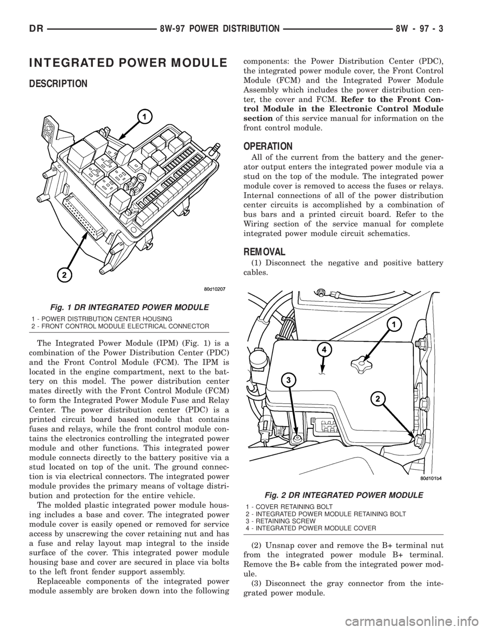
The Integrated Power Module (IPM) (Fig. 1) is a
combination of the Power Distribution Center (PDC)
and the Front Control Module (FCM). The IPM is
located in the engine compartment, next to the bat-
tery on this model. The power distribution center
mates directly with the Front Control Module (FCM)
to form the Integrated Power Module Fuse and Relay
Center. The power distribution center (PDC) is a
printed circuit board based module that contains
fuses and relays, while the front control module con-
tains the electronics controlling the integrated power
module and other functions. This integrated power
module connects directly to the battery positive via a
stud located on top of the unit. The ground connec-
tion is via electrical connectors. The integrated power
module provides the primary means of voltage distri-
bution and protection for the entire vehicle.
The molded plastic integrated power module hous-
ing includes a base and cover. The integrated power
module cover is easily opened or removed for service
access by unscrewing the cover retaining nut and has
a fuse and relay layout map integral to the inside
surface of the cover. This integrated power module
housing base and cover are secured in place via bolts
to the left front fender support assembly.
Replaceable components of the integrated power
module assembly are broken down into the followingcomponents: the Power Distribution Center (PDC),
the integrated power module cover, the Front Control
Module (FCM) and the Integrated Power Module
Assembly which includes the power distribution cen-
ter, the cover and FCM.Refer to the Front Con-
trol Module in the Electronic Control Module
sectionof this service manual for information on the
front control module.
OPERATION
All of the current from the battery and the gener-
ator output enters the integrated power module via a
stud on the top of the module. The integrated power
module cover is removed to access the fuses or relays.
Internal connections of all of the power distribution
center circuits is accomplished by a combination of
bus bars and a printed circuit board. Refer to the
Wiring section of the service manual for complete
integrated power module circuit schematics.
REMOVAL
(1) Disconnect the negative and positive battery
cables.
(2) Unsnap cover and remove the B+ terminal nut
from the integrated power module B+ terminal.
Remove the B+ cable from the integrated power mod-
ule.
(3) Disconnect the gray connector from the inte-
grated power module.
Fig. 1 DR INTEGRATED POWER MODULE
1 - POWER DISTRIBUTION CENTER HOUSING
2 - FRONT CONTROL MODULE ELECTRICAL CONNECTOR
Fig. 2 DR INTEGRATED POWER MODULE
1 - COVER RETAINING BOLT
2 - INTEGRATED POWER MODULE RETAINING BOLT
3 - RETAINING SCREW
4 - INTEGRATED POWER MODULE COVER
DR8W-97 POWER DISTRIBUTION 8W - 97 - 3
Page 1243 of 2895
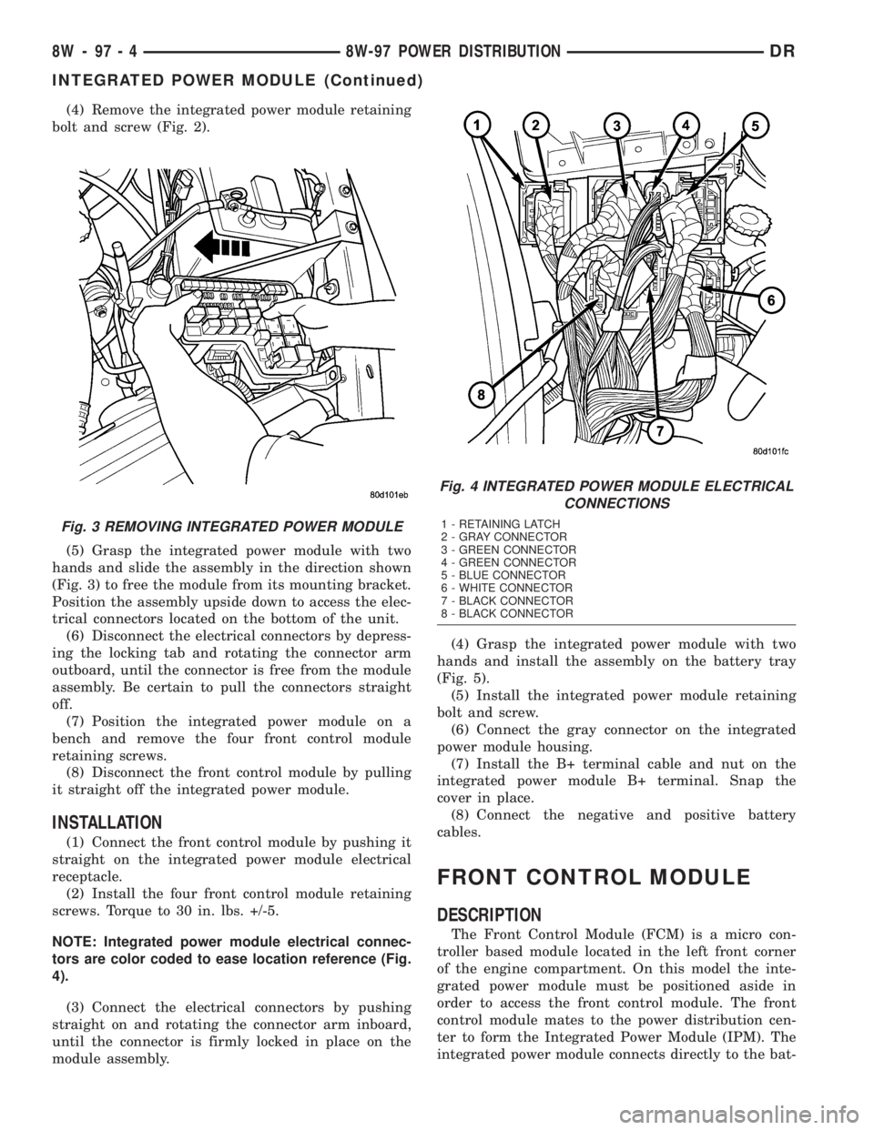
(4) Remove the integrated power module retaining
bolt and screw (Fig. 2).
(5) Grasp the integrated power module with two
hands and slide the assembly in the direction shown
(Fig. 3) to free the module from its mounting bracket.
Position the assembly upside down to access the elec-
trical connectors located on the bottom of the unit.
(6) Disconnect the electrical connectors by depress-
ing the locking tab and rotating the connector arm
outboard, until the connector is free from the module
assembly. Be certain to pull the connectors straight
off.
(7) Position the integrated power module on a
bench and remove the four front control module
retaining screws.
(8) Disconnect the front control module by pulling
it straight off the integrated power module.
INSTALLATION
(1) Connect the front control module by pushing it
straight on the integrated power module electrical
receptacle.
(2) Install the four front control module retaining
screws. Torque to 30 in. lbs. +/-5.
NOTE: Integrated power module electrical connec-
tors are color coded to ease location reference (Fig.
4).
(3) Connect the electrical connectors by pushing
straight on and rotating the connector arm inboard,
until the connector is firmly locked in place on the
module assembly.(4) Grasp the integrated power module with two
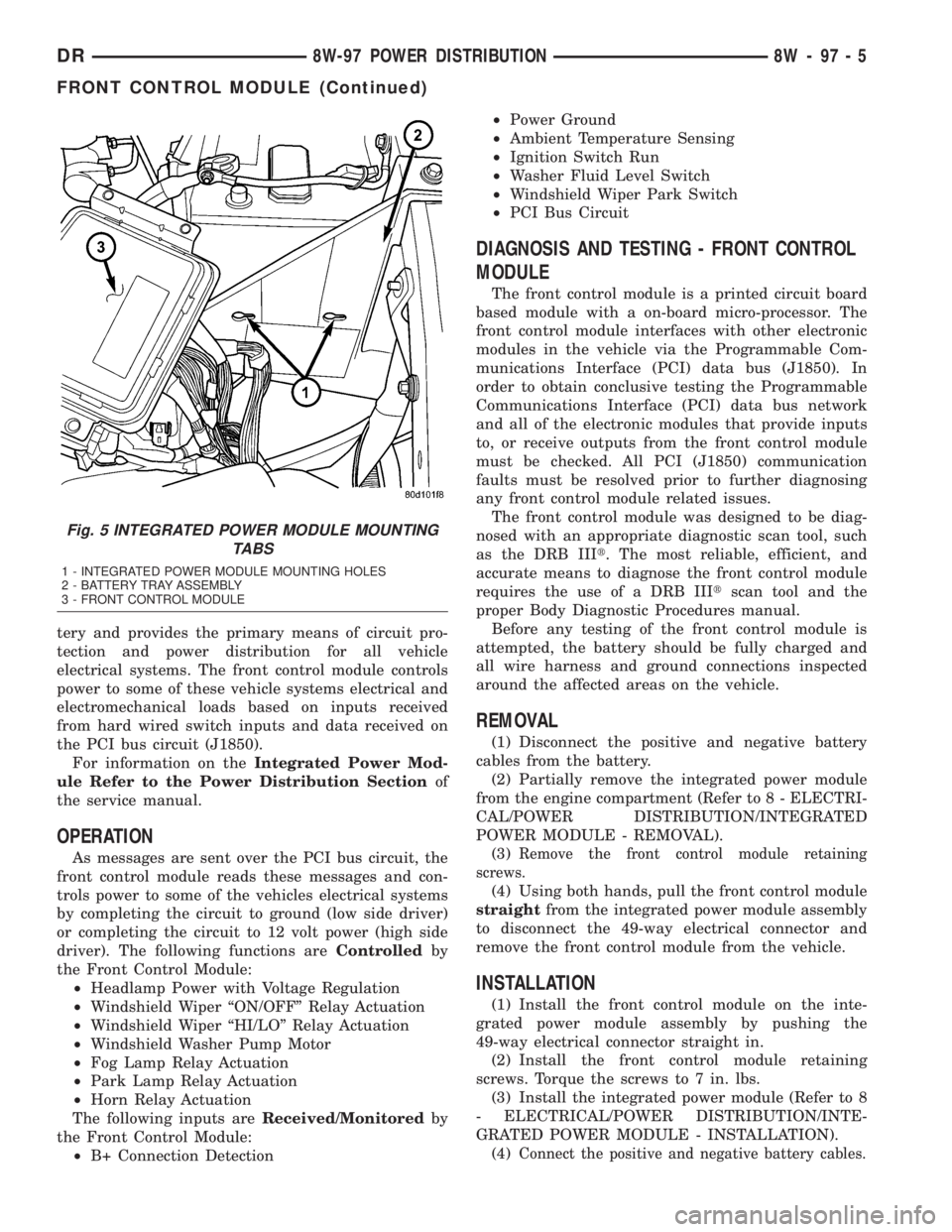
hands and install the assembly on the battery tray
(Fig. 5).
(5) Install the integrated power module retaining
bolt and screw.
(6) Connect the gray connector on the integrated
power module housing.
(7) Install the B+ terminal cable and nut on the
integrated power module B+ terminal. Snap the
cover in place.
(8) Connect the negative and positive battery
cables.
FRONT CONTROL MODULE
DESCRIPTION
The Front Control Module (FCM) is a micro con-
troller based module located in the left front corner
of the engine compartment. On this model the inte-
grated power module must be positioned aside in
order to access the front control module. The front
control module mates to the power distribution cen-
ter to form the Integrated Power Module (IPM). The
integrated power module connects directly to the bat-
Fig. 3 REMOVING INTEGRATED POWER MODULE
Fig. 4 INTEGRATED POWER MODULE ELECTRICAL
CONNECTIONS
1 - RETAINING LATCH
2 - GRAY CONNECTOR
3 - GREEN CONNECTOR
4 - GREEN CONNECTOR
5 - BLUE CONNECTOR
6 - WHITE CONNECTOR
7 - BLACK CONNECTOR
8 - BLACK CONNECTOR
8W - 97 - 4 8W-97 POWER DISTRIBUTIONDR
INTEGRATED POWER MODULE (Continued)
Page 1244 of 2895
tery and provides the primary means of circuit pro-
tection and power distribution for all vehicle
electrical systems. The front control module controls
power to some of these vehicle systems electrical and
electromechanical loads based on inputs received
from hard wired switch inputs and data received on
the PCI bus circuit (J1850).
For information on theIntegrated Power Mod-
ule Refer to the Power Distribution Sectionof
the service manual.
OPERATION
As messages are sent over the PCI bus circuit, the
front control module reads these messages and con-
trols power to some of the vehicles electrical systems
by completing the circuit to ground (low side driver)
or completing the circuit to 12 volt power (high side
driver). The following functions areControlledby
the Front Control Module:
²Headlamp Power with Voltage Regulation
²Windshield Wiper ªON/OFFº Relay Actuation
²Windshield Wiper ªHI/LOº Relay Actuation
²Windshield Washer Pump Motor
²Fog Lamp Relay Actuation
²Park Lamp Relay Actuation
²Horn Relay Actuation
The following inputs areReceived/Monitoredby
the Front Control Module:
²B+ Connection Detection²Power Ground
²Ambient Temperature Sensing
²Ignition Switch Run
²Washer Fluid Level Switch
²Windshield Wiper Park Switch
²PCI Bus Circuit
DIAGNOSIS AND TESTING - FRONT CONTROL
MODULE
The front control module is a printed circuit board
based module with a on-board micro-processor. The
front control module interfaces with other electronic
modules in the vehicle via the Programmable Com-
munications Interface (PCI) data bus (J1850). In
order to obtain conclusive testing the Programmable
Communications Interface (PCI) data bus network
and all of the electronic modules that provide inputs
to, or receive outputs from the front control module
must be checked. All PCI (J1850) communication
faults must be resolved prior to further diagnosing
any front control module related issues.
The front control module was designed to be diag-
nosed with an appropriate diagnostic scan tool, such
as the DRB IIIt. The most reliable, efficient, and
accurate means to diagnose the front control module
requires the use of a DRB IIItscan tool and the
proper Body Diagnostic Procedures manual.
Before any testing of the front control module is
attempted, the battery should be fully charged and
all wire harness and ground connections inspected
around the affected areas on the vehicle.
REMOVAL
(1) Disconnect the positive and negative battery
cables from the battery.
(2) Partially remove the integrated power module
from the engine compartment (Refer to 8 - ELECTRI-
CAL/POWER DISTRIBUTION/INTEGRATED
POWER MODULE - REMOVAL).
(3)
Remove the front control module retaining
screws.
(4) Using both hands, pull the front control module
straightfrom the integrated power module assembly
to disconnect the 49-way electrical connector and
remove the front control module from the vehicle.
INSTALLATION
(1) Install the front control module on the inte-
grated power module assembly by pushing the
49-way electrical connector straight in.
(2) Install the front control module retaining
screws. Torque the screws to 7 in. lbs.
(3) Install the integrated power module (Refer to 8
- ELECTRICAL/POWER DISTRIBUTION/INTE-
GRATED POWER MODULE - INSTALLATION).
(4)
Connect the positive and negative battery cables.
Fig. 5 INTEGRATED POWER MODULE MOUNTING
TABS
1 - INTEGRATED POWER MODULE MOUNTING HOLES
2 - BATTERY TRAY ASSEMBLY
3 - FRONT CONTROL MODULE
DR8W-97 POWER DISTRIBUTION 8W - 97 - 5
FRONT CONTROL MODULE (Continued)
Page 1245 of 2895
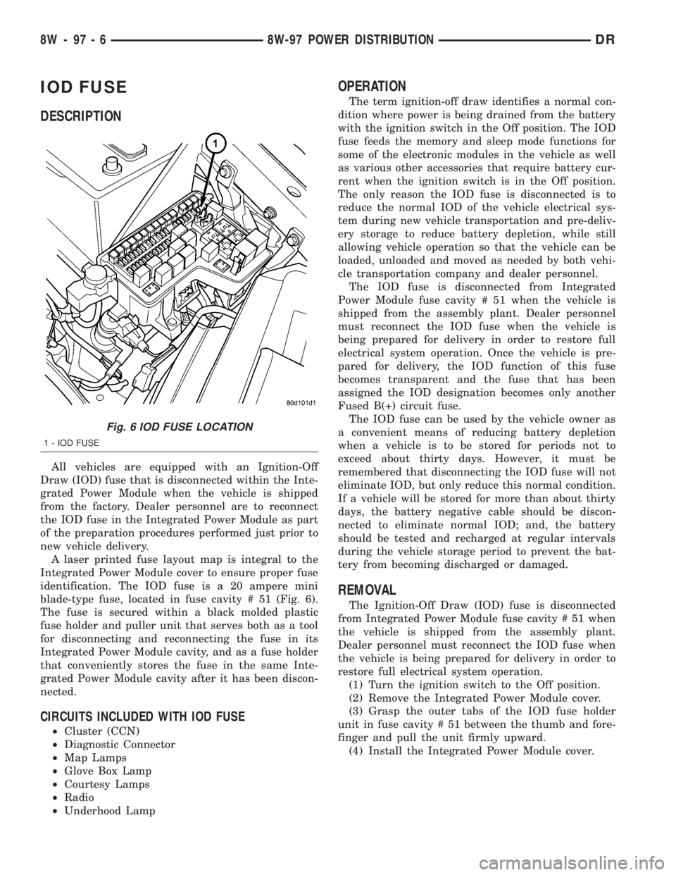
IOD FUSE
DESCRIPTION
All vehicles are equipped with an Ignition-Off
Draw (IOD) fuse that is disconnected within the Inte-
grated Power Module when the vehicle is shipped
from the factory. Dealer personnel are to reconnect
the IOD fuse in the Integrated Power Module as part
of the preparation procedures performed just prior to
new vehicle delivery.
A laser printed fuse layout map is integral to the
Integrated Power Module cover to ensure proper fuse
identification. The IOD fuse is a 20 ampere mini
blade-type fuse, located in fuse cavity # 51 (Fig. 6).
The fuse is secured within a black molded plastic
fuse holder and puller unit that serves both as a tool
for disconnecting and reconnecting the fuse in its
Integrated Power Module cavity, and as a fuse holder
that conveniently stores the fuse in the same Inte-
grated Power Module cavity after it has been discon-
nected.
CIRCUITS INCLUDED WITH IOD FUSE
²Cluster (CCN)
²Diagnostic Connector
²Map Lamps
²Glove Box Lamp
²Courtesy Lamps
²Radio
²Underhood Lamp
OPERATION
The term ignition-off draw identifies a normal con-
dition where power is being drained from the battery
with the ignition switch in the Off position. The IOD
fuse feeds the memory and sleep mode functions for
some of the electronic modules in the vehicle as well
as various other accessories that require battery cur-
rent when the ignition switch is in the Off position.
The only reason the IOD fuse is disconnected is to
reduce the normal IOD of the vehicle electrical sys-
tem during new vehicle transportation and pre-deliv-
ery storage to reduce battery depletion, while still
allowing vehicle operation so that the vehicle can be
loaded, unloaded and moved as needed by both vehi-
cle transportation company and dealer personnel.
The IOD fuse is disconnected from Integrated
Power Module fuse cavity # 51 when the vehicle is
shipped from the assembly plant. Dealer personnel
must reconnect the IOD fuse when the vehicle is
being prepared for delivery in order to restore full
electrical system operation. Once the vehicle is pre-
pared for delivery, the IOD function of this fuse
becomes transparent and the fuse that has been
assigned the IOD designation becomes only another
Fused B(+) circuit fuse.
The IOD fuse can be used by the vehicle owner as
a convenient means of reducing battery depletion
when a vehicle is to be stored for periods not to
exceed about thirty days. However, it must be
remembered that disconnecting the IOD fuse will not
eliminate IOD, but only reduce this normal condition.
If a vehicle will be stored for more than about thirty
days, the battery negative cable should be discon-
nected to eliminate normal IOD; and, the battery
should be tested and recharged at regular intervals
during the vehicle storage period to prevent the bat-
tery from becoming discharged or damaged.
REMOVAL
The Ignition-Off Draw (IOD) fuse is disconnected
from Integrated Power Module fuse cavity # 51 when
the vehicle is shipped from the assembly plant.
Dealer personnel must reconnect the IOD fuse when
the vehicle is being prepared for delivery in order to
restore full electrical system operation.
(1) Turn the ignition switch to the Off position.
(2) Remove the Integrated Power Module cover.
(3) Grasp the outer tabs of the IOD fuse holder
unit in fuse cavity # 51 between the thumb and fore-
finger and pull the unit firmly upward.
(4) Install the Integrated Power Module cover.
Fig. 6 IOD FUSE LOCATION
1 - IOD FUSE
8W - 97 - 6 8W-97 POWER DISTRIBUTIONDR
Page 1246 of 2895
INSTALLATION
(1) Turn the ignition switch to the Off position.
(2) Remove the Integrated Power Module cover.
(3) To install the IOD fuse, use a thumb to press
the IOD fuse holder unit in fuse cavity # 51 firmly
into the Integrated Power Module.
(4) Install the Integrated Power Module cover.
POWER OUTLET
DESCRIPTION
Two power outlets are utilized on this model. One
in the instrument panel center lower bezel and the
other in the center console. The power outlet bases
are secured by a snap fit within the instrument
panel or trim panel. A plastic protective cap snaps
into the power outlet base when the power outlet is
not being used, and hangs from the power outlet base
mount by an integral bail strap while the power out-
let is in use.
The power outlet receptacle unit and the accessory
power outlet protective cap are available for service.
The power outlet receptacle cannot be repaired and,
if faulty or damaged, it must be replaced.
OPERATION
The power outlet base or receptacle shell is con-
nected to ground, and an insulated contact in the
bottom of the shell is connected to battery current.
The power outlet receives battery voltage from a fuse
in the integrated power module at all times.
While the power outlet is very similar to a cigar
lighter base unit, it does not include the two small
spring-clip retainers inside the bottom of the recepta-
cle shell that are used to secure the cigar lighter
heating element to the insulated contact.
DIAGNOSIS AND TESTING - POWER OUTLET
For complete circuit diagrams, refer toWiring
Diagrams.
(1) Check the fused B(+) fuse in the integrated
power module. If OK, go to Step 2. If not OK, repair
the shorted circuit or component as required and
replace the faulty fuse.
(2) Check for battery voltage at the fused B(+) fuse
in the integrated power module. If OK, go to Step 3.
If not OK, repair the open fused B(+) circuit to the
battery as required.
(3) Remove the plastic protective cap from the
power outlet receptacle. Check for continuity between
the inside circumference of the power outlet recepta-
cle and a good ground. There should be continuity. If
OK, go to Step 4. If not OK, go to Step 5.(4) Check for battery voltage at the insulated con-
tact located at the back of the power outlet recepta-
cle. If not OK, go to Step 5.
(5) Disconnect and isolate the battery negative
cable. Remove the power outlet receptacle from the
instrument panel. Disconnect the wire harness con-
nector from the power outlet receptacle. Check for
continuity between the ground circuit cavity of the
power outlet wire harness connector and a good
ground. There should be continuity. If OK, go to Step
6. If not OK, repair the open ground circuit to ground
as required.
(6) Connect the battery negative cable. Check for
battery voltage at the fused B(+) circuit cavity of the
power outlet wire harness connector. If OK, replace
the faulty power outlet receptacle. If not OK, repair
the open fused B(+) circuit to the integrated power
module fuse as required.
REMOVAL
(1) Disconnect and isolate the battery negative
cable.
(2) Pull the cigar lighter knob and element out of
the cigar lighter receptacle base, or unsnap the pro-
tective cap from the power outlet receptacle base.
(3) Look inside the cigar lighter or power outlet
receptacle base and note the position of the rectangu-
lar retaining bosses of the mount that secures the
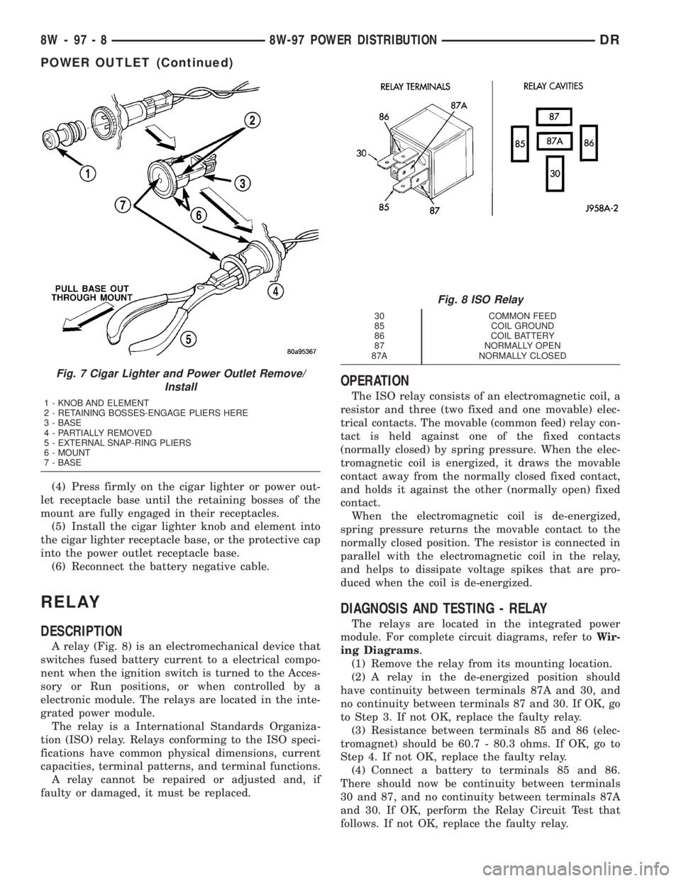
receptacle base to the panel (Fig. 7).
(4) Insert a pair of external snap ring pliers into
the cigar lighter or power outlet receptacle base and
engage the tips of the pliers with the retaining
bosses of the mount.
(5) Squeeze the pliers to disengage the mount
retaining bosses from the receptacle base and, using
a gentle rocking motion, pull the pliers and the
receptacle base out of the mount.
(6) Pull the receptacle base away from the instru-
ment panel far enough to access the instrument
panel wire harness connector.
(7) Disconnect the instrument panel wire harness
connector from the cigar lighter or power outlet
receptacle base connector receptacle.
(8) Remove the cigar lighter or power outlet mount
from the instrument panel.
INSTALLATION
(1) Reconnect the instrument panel wire harness
connector to the cigar lighter or power outlet recep-
tacle base connector receptacle.
(2) Install the cigar lighter or power outlet mount
into the instrument panel.
(3) Align the splines on the outside of the cigar
lighter or power outlet receptacle base connector
receptacle with the grooves on the inside of the
mount.
DR8W-97 POWER DISTRIBUTION 8W - 97 - 7
IOD FUSE (Continued)
Page 1247 of 2895
(4) Press firmly on the cigar lighter or power out-
let receptacle base until the retaining bosses of the
mount are fully engaged in their receptacles.
(5) Install the cigar lighter knob and element into
the cigar lighter receptacle base, or the protective cap
into the power outlet receptacle base.
(6) Reconnect the battery negative cable.
RELAY
DESCRIPTION
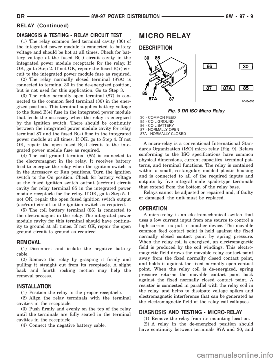
A relay (Fig. 8) is an electromechanical device that
switches fused battery current to a electrical compo-
nent when the ignition switch is turned to the Acces-
sory or Run positions, or when controlled by a
electronic module. The relays are located in the inte-
grated power module.
The relay is a International Standards Organiza-
tion (ISO) relay. Relays conforming to the ISO speci-
fications have common physical dimensions, current
capacities, terminal patterns, and terminal functions.
A relay cannot be repaired or adjusted and, if
faulty or damaged, it must be replaced.
OPERATION
The ISO relay consists of an electromagnetic coil, a
resistor and three (two fixed and one movable) elec-
trical contacts. The movable (common feed) relay con-
tact is held against one of the fixed contacts
(normally closed) by spring pressure. When the elec-
tromagnetic coil is energized, it draws the movable
contact away from the normally closed fixed contact,
and holds it against the other (normally open) fixed
contact.
When the electromagnetic coil is de-energized,
spring pressure returns the movable contact to the
normally closed position. The resistor is connected in
parallel with the electromagnetic coil in the relay,
and helps to dissipate voltage spikes that are pro-
duced when the coil is de-energized.
DIAGNOSIS AND TESTING - RELAY
The relays are located in the integrated power
module. For complete circuit diagrams, refer toWir-
ing Diagrams.
(1) Remove the relay from its mounting location.
(2) A relay in the de-energized position should
have continuity between terminals 87A and 30, and
no continuity between terminals 87 and 30. If OK, go
to Step 3. If not OK, replace the faulty relay.
(3) Resistance between terminals 85 and 86 (elec-
tromagnet) should be 60.7 - 80.3 ohms. If OK, go to
Step 4. If not OK, replace the faulty relay.
(4) Connect a battery to terminals 85 and 86.
There should now be continuity between terminals
30 and 87, and no continuity between terminals 87A
and 30. If OK, perform the Relay Circuit Test that
follows. If not OK, replace the faulty relay.
Fig. 7 Cigar Lighter and Power Outlet Remove/
Install
1 - KNOB AND ELEMENT
2 - RETAINING BOSSES-ENGAGE PLIERS HERE
3 - BASE
4 - PARTIALLY REMOVED
5 - EXTERNAL SNAP-RING PLIERS
6 - MOUNT
7 - BASE
Fig. 8 ISO Relay
30 COMMON FEED
85 COIL GROUND
86 COIL BATTERY
87 NORMALLY OPEN
87A NORMALLY CLOSED
8W - 97 - 8 8W-97 POWER DISTRIBUTIONDR
POWER OUTLET (Continued)
Page 1248 of 2895
DIAGNOSIS & TESTING - RELAY CIRCUIT TEST
(1) The relay common feed terminal cavity (30) of
the integrated power module is connected to battery
voltage and should be hot at all times. Check for bat-
tery voltage at the fused B(+) circuit cavity in the
integrated power module receptacle for the relay. If
OK, go to Step 2. If not OK, repair the fused B(+) cir-
cuit to the integrated power module fuse as required.
(2) The relay normally closed terminal (87A) is
connected to terminal 30 in the de-energized position,
but is not used for this application. Go to Step 3.
(3) The relay normally open terminal (87) is con-
nected to the common feed terminal (30) in the ener-
gized position. This terminal supplies battery voltage
to the fused B(+) fuse in the integrated power module
that feeds the accessory when the relay is energized
by the ignition switch. There should be continuity
between the integrated power module cavity for relay
terminal 87 and the fused B(+) fuse in the integrated
power module at all times. If OK, go to Step 4. If not
OK, repair the open fused B(+) circuit to the inte-
grated power module fuse as required.
(4) The coil ground terminal (85) is connected to
the electromagnet in the relay. It receives battery
feed to energize the relay when the ignition switch is
in the Accessory or Run positions. Turn the ignition
switch to the On position. Check for battery voltage
at the fused ignition switch output (acc/run) circuit
cavity for relay terminal 85 in the integrated power
module receptacle for the relay. If OK, go to Step 5. If
not OK, repair the open fused ignition switch output
(acc/run) circuit to the ignition switch as required.
(5) The coil battery terminal (86) is connected to
the electromagnet in the relay. The integrated power
module cavity for this terminal should have continu-
ity to ground at all times. If not OK, repair the open
ground circuit to ground as required.
REMOVAL
(1) Disconnect and isolate the negative battery
cable.
(2) Remove the relay by grasping it firmly and
pulling it straight out from its receptacle. A slight
back and fourth rocking motion may help the
removal process.
INSTALLATION
(1) Position the relay to the proper receptacle.
(2) Align the relay terminals with the terminal
cavities in the receptacle.
(3) Push firmly and evenly on the top of the relay
until the terminals are fully seated in the terminal
cavities in the receptacle.
(4) Connect the negative battery cable.
MICRO RELAY
DESCRIPTION
A micro-relay is a conventional International Stan-
dards Organization (ISO) micro relay (Fig. 9). Relays
conforming to the ISO specifications have common
physical dimensions, current capacities, terminal pat-
terns, and terminal functions. The relay is contained
within a small, rectangular, molded plastic housing
and is connected to all of the required inputs and
outputs by five integral male spade-type terminals
that extend from the bottom of the relay base.
Relays cannot be adjusted or repaired and, if faulty
or damaged, the unit must be replaced.
OPERATION
A micro-relay is an electromechanical switch that
uses a low current input from one source to control a
high current output to another device. The movable
common feed contact point is held against the fixed
normally closed contact point by spring pressure.
When the relay coil is energized, an electromagnetic
field is produced by the coil windings. This electro-
magnetic field draws the movable relay contact point
away from the fixed normally closed contact point,
and holds it against the fixed normally open contact
point. When the relay coil is de-energized, spring
pressure returns the movable contact point back
against the fixed normally closed contact point. A
resistor is connected in parallel with the relay coil in
the relay, and helps to dissipate voltage spikes and
electromagnetic interference that can be generated as
the electromagnetic field of the relay coil collapses.
DIAGNOSIS AND TESTING - MICRO-RELAY
(1) Remove the relay from its mounting location.
(2) A relay in the de-energized position should
have continuity between terminals 87A and 30, and
Fig. 9 DR ISO Micro Relay
30 - COMMON FEED
85 - COIL GROUND
86 - COIL BATTERY
87 - NORMALLY OPEN
87A - NORMALLY CLOSED
DR8W-97 POWER DISTRIBUTION 8W - 97 - 9
RELAY (Continued)
Page 1249 of 2895
no continuity between terminals 87 and 30. If OK, go
to Step 3. If not OK, replace the faulty relay.
(3) Resistance between terminals 85 and 86 (elec-
tromagnet) should be 67.5 - 82.5 ohms. If OK, go to
Step 4. If not OK, replace the faulty relay.
(4) Connect a battery to terminals 85 and 86.
There should now be continuity between terminals
30 and 87, and no continuity between terminals 87A
and 30. If OK, reinstall the relay and use a DRB IIIt
scan tool to perform further testing. Refer to the
appropriate diagnostic information.
Refer to the appropriate wiring information. The
wiring information includes wiring diagrams, proper
wire and connector repair procedures, details of wire
harness routing and retention, connector pin-out
information and location views for the various wire
harness connectors, splices and grounds.REMOVAL
(1) Disconnect and isolate the negative battery
cable.
(2) Remove the relay by grasping it firmly and
pulling it straight out from its receptacle. A slight
back and fourth rocking motion may help the
removal process.
INSTALLATION
(1) Align the micro-relay terminals with the termi-
nal cavities in the receptacle.
(2) Push firmly and evenly on the top of the relay
until the terminals are fully seated in the terminal
cavities in the receptacle.
(3) Connect the battery negative cable.
8W - 97 - 10 8W-97 POWER DISTRIBUTIONDR
MICRO RELAY (Continued)
Page 1250 of 2895
ENGINE
TABLE OF CONTENTS
page page
ENGINE - 3.7L............................ 1
ENGINE - 4.7L........................... 87
ENGINE - 5.7L.......................... 176ENGINE - 5.9L.......................... 223
ENGINE 5.9L DIESEL..................... 280
ENGINE 8.0L............................ 351
ENGINE - 3.7L
TABLE OF CONTENTS
page page
ENGINE - 3.7L
DESCRIPTION..........................3
DIAGNOSIS AND TESTING
DIAGNOSIS AND TESTING - ENGINE
DIAGNOSIS - INTRODUCTION............4
DIAGNOSIS AND TESTING - ENGINE
DIAGNOSIS - PERFORMANCE............4
DIAGNOSIS AND TESTING - ENGINE
DIAGNOSIS - MECHANICAL..............6
DIAGNOSIS AND TESTING - ENGINE
DIAGNOSIS - LUBRICATION..............7
DIAGNOSIS AND TESTING - CYLINDER
COMPRESSION PRESSURE..............8
DIAGNOSIS AND TESTING - CYLINDER
COMBUSTION PRESSURE LEAKAGE.......8
STANDARD PROCEDURE
STANDARD PROCEDURE - REPAIR
DAMAGED OR WORN THREADS..........9
STANDARD PROCEDURE - FORM-IN-
PLACE GASKETS AND SEALERS..........9
STANDARD PROCEDURE - ENGINE
GASKET SURFACE PREPARATION........10
REMOVAL.............................10
INSTALLATION.........................11
SPECIFICATIONS
SPECIFICATIONS ± 3.7L ENGINE.........12
TORQUE............................15
SPECIAL TOOLS.......................16
AIR CLEANER ELEMENT
REMOVAL.............................20
INSTALLATION.........................20
CYLINDER HEAD - LEFT
DIAGNOSIS AND TESTING - CYLINDER HEAD
GASKET............................20
REMOVAL.............................21
INSTALLATION.........................23CAMSHAFT(S)
DESCRIPTION.........................24
REMOVAL.............................24
INSTALLATION.........................25
CYLINDER HEAD COVER(S)
DESCRIPTION.........................26
REMOVAL.............................26
INSTALLATION.........................27
INTAKE/EXHAUST VALVES & SEATS
DESCRIPTION.........................27
STANDARD PROCEDURE - REFACING......27
REMOVAL.............................28
INSTALLATION.........................29
ROCKER ARM
DESCRIPTION.........................30
REMOVAL.............................30
INSTALLATION.........................30
VALVE GUIDE SEALS
DESCRIPTION.........................31
VALVE SPRINGS
DESCRIPTION.........................31
REMOVAL.............................31
INSTALLATION.........................31
CYLINDER HEAD - RIGHT
DIAGNOSIS AND TESTING - HYDRAULIC
LASH ADJUSTER.....................31
REMOVAL.............................32
INSTALLATION.........................32
CAMSHAFT(S)
DESCRIPTION.........................34
REMOVAL.............................34
INSTALLATION.........................35
CYLINDER HEAD COVER(S)
REMOVAL.............................35
INSTALLATION.........................36
DRENGINE 9 - 1