DODGE RAM 2003 Service Repair Manual
Manufacturer: DODGE, Model Year: 2003, Model line: RAM, Model: DODGE RAM 2003Pages: 2895, PDF Size: 83.15 MB
Page 181 of 2895
SPECIFICATIONS
AXLE SPECIFICATIONS
DESCRIPTION SPECIFICATION
Axle Ratio 3.73, 4.10
Ring Gear Diameter 266 mm (10.5 in.)
Ring Gear Backlash 0.13-0.18 mm (0.005-0.007 in.)
Pinion Bearing Preload - New Bearings 1.69-2.82 N´m (15-25 in. lbs.)
Pinion Bearing Preload - Original Bearings 1-2 N´m (10-20 in. lbs.)
Pinion Bearing Preload + Diff Case Bearing Preload -
New Bearings3.4-5.6 N´m (30-50 in. lbs.)
Pinion Bearing Preload + Diff Case Bearing Preload -
Original Bearings2.8-5.1 N´m (25-45 in. lbs.)
TORQUE SPECIFICATIONS
DESCRIPTION N´m Ft. Lbs. In. Lbs.
Fill Hole Plug 32 24 -
Differential Cover Bolts 40 30 -
Bearing Cap Bolts 165 122 -
Ring Gear Bolts 237 175 -
Axle Flange Bolts 129 95 -
Adjuster Lock Bolt 25 18 -
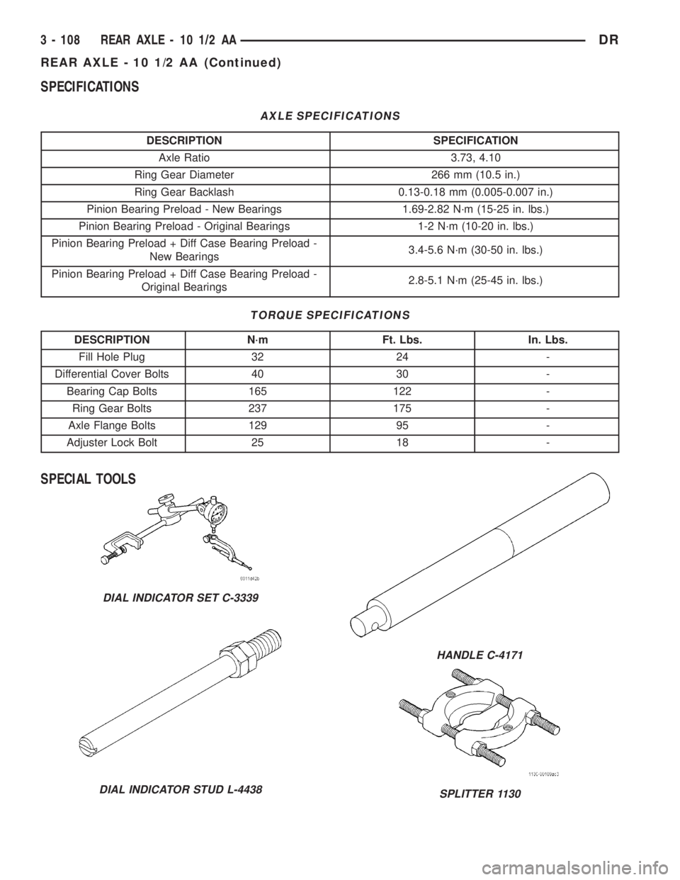
SPECIAL TOOLS
DIAL INDICATOR SET C-3339
DIAL INDICATOR STUD L-4438
HANDLE C-4171
SPLITTER 1130
3 - 108 REAR AXLE - 10 1/2 AADR
REAR AXLE - 10 1/2 AA (Continued)
Page 182 of 2895
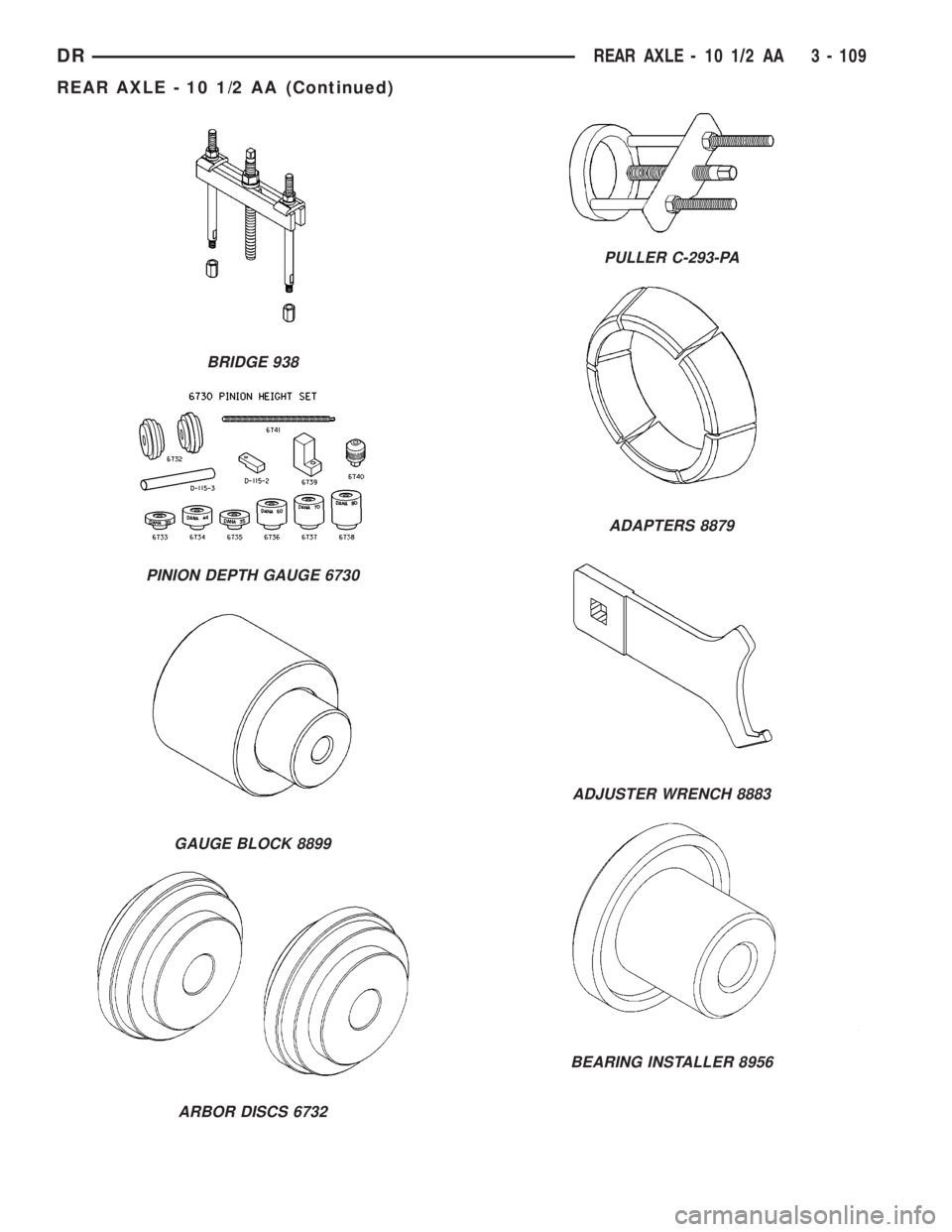
BRIDGE 938
PINION DEPTH GAUGE 6730
GAUGE BLOCK 8899
ARBOR DISCS 6732
PULLER C-293-PA
ADAPTERS 8879
ADJUSTER WRENCH 8883
BEARING INSTALLER 8956
DRREAR AXLE - 10 1/2 AA 3 - 109
REAR AXLE - 10 1/2 AA (Continued)
Page 183 of 2895
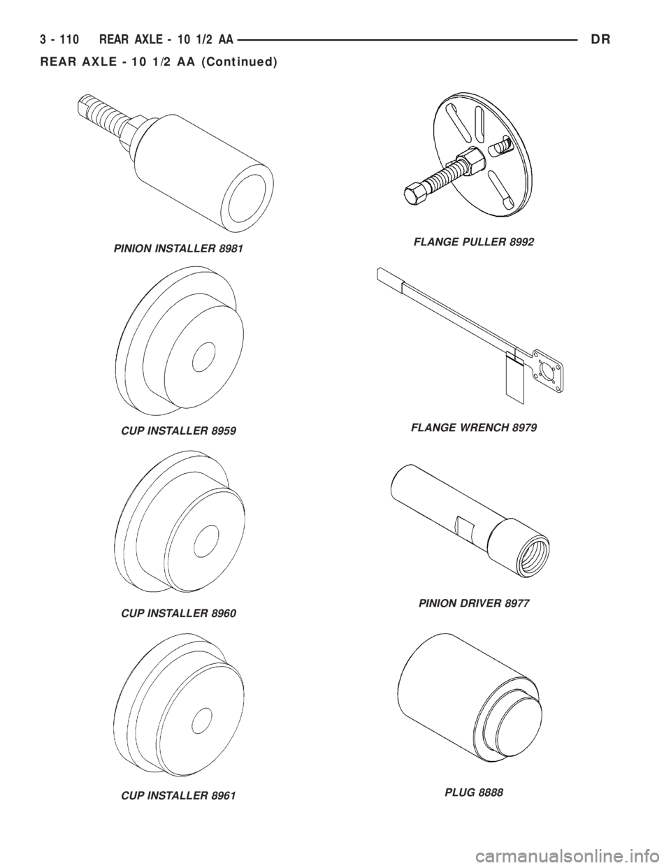
PINION INSTALLER 8981
CUP INSTALLER 8959
CUP INSTALLER 8960
CUP INSTALLER 8961
FLANGE PULLER 8992
FLANGE WRENCH 8979
PINION DRIVER 8977
PLUG 8888
3 - 110 REAR AXLE - 10 1/2 AADR
REAR AXLE - 10 1/2 AA (Continued)
Page 184 of 2895
AXLE SHAFTS
REMOVAL
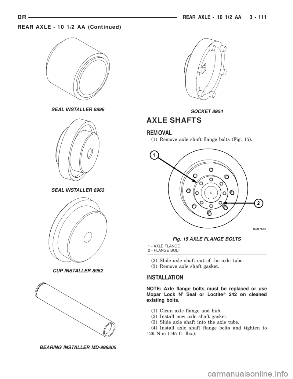
(1) Remove axle shaft flange bolts (Fig. 15).
(2) Slide axle shaft out of the axle tube.
(3) Remove axle shaft gasket.
INSTALLATION
NOTE: Axle flange bolts must be replaced or use
Mopar Lock N' Seal or LoctiteT242 on cleaned
existing bolts.
(1) Clean axle flange and hub.
(2) Install new axle shaft gasket.
(3) Slide axle shaft into the axle tube.
(4) Install axle shaft flange bolts and tighten to
129 N´m ( 95 ft. lbs.).
SEAL INSTALLER 8896
SEAL INSTALLER 8963
CUP INSTALLER 8962
BEARING INSTALLER MD-998805
SOCKET 8954
Fig. 15 AXLE FLANGE BOLTS
1 - AXLE FLANGE
2 - FLANGE BOLT
DRREAR AXLE - 10 1/2 AA 3 - 111
REAR AXLE - 10 1/2 AA (Continued)
Page 185 of 2895
AXLE BEARINGS
REMOVAL
(1) Remove axle shaft flange bolts and remove axle
shaft.
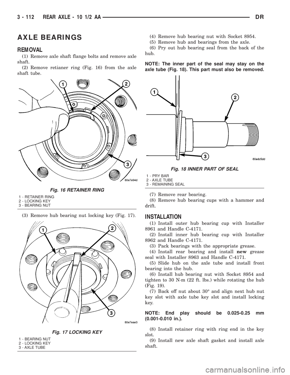
(2) Remove retianer ring (Fig. 16) from the axle
shaft tube.
(3) Remove hub bearing nut locking key (Fig. 17).(4) Remove hub bearing nut with Socket 8954.
(5) Remove hub and bearings from the axle.
(6) Pry out hub bearing seal from the back of the
hub.
NOTE: The inner part of the seal may stay on the
axle tube (Fig. 18). This part must also be removed.
(7) Remove rear bearing.
(8) Remove hub bearing cups with a hammer and
drift.
INSTALLATION
(1) Install outer hub bearing cup with Installer
8961 and Handle C-4171.
(2) Install inner hub bearing cup with Installer
8962 and Handle C-4171.
(3) Pack bearings with the appropriate grease.
(4) Install rear bearing and installnewgrease
seal with Installer 8963 and Handle C-4171.
(5) Slide hub on the axle tube and install front
bearing into the hub.
(6) Install hub bearing nut with Socket 8954 and
tighten to 30 N´m (22 ft. lbs.) while rotating the hub
(Fig. 19).
(7) Back off nut about 30É and align next hub nut
key slot with axle tube key slot and install locking
key.
NOTE: End play should be 0.025-0.25 mm
(0.001-0.010 in.).
(8) Install retainer ring with ring end in the key
slot.
(9) Install new axle shaft gasket and install axle
shaft.
Fig. 16 RETAINER RING
1 - RETAINER RING
2 - LOCKING KEY
3 - BEARING NUT
Fig. 17 LOCKING KEY
1 - BEARING NUT
2 - LOCKING KEY
3 - AXLE TUBE
Fig. 18 INNER PART OF SEAL
1-PRYBAR
2 - AXLE TUBE
3 - REMAINING SEAL
3 - 112 REAR AXLE - 10 1/2 AADR
Page 186 of 2895
PINION SEAL
REMOVAL
(1) Remove axle shafts.
(2) Mark propeller shaft and pinion flange for
installation reference and remove shaft.
(3) Rotate pinion gear three or four times.
(4) Measure and record the amount of torque nec-
essary to rotate the pinion gear with an inch pound
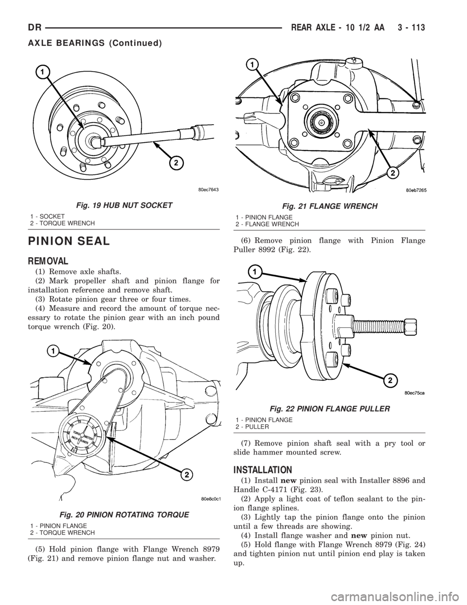
torque wrench (Fig. 20).
(5) Hold pinion flange with Flange Wrench 8979
(Fig. 21) and remove pinion flange nut and washer.(6) Remove pinion flange with Pinion Flange
Puller 8992 (Fig. 22).
(7) Remove pinion shaft seal with a pry tool or
slide hammer mounted screw.
INSTALLATION
(1) Installnewpinion seal with Installer 8896 and
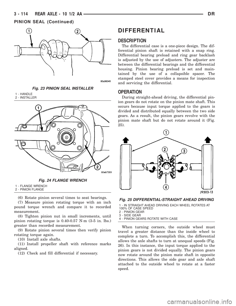
Handle C-4171 (Fig. 23).
(2) Apply a light coat of teflon sealant to the pin-
ion flange splines.
(3) Lightly tap the pinion flange onto the pinion
until a few threads are showing.
(4) Install flange washer andnewpinion nut.
(5) Hold flange with Flange Wrench 8979 (Fig. 24)
and tighten pinion nut until pinion end play is taken
up.
Fig. 19 HUB NUT SOCKET
1 - SOCKET
2 - TORQUE WRENCH
Fig. 20 PINION ROTATING TORQUE
1 - PINION FLANGE
2 - TORQUE WRENCH
Fig. 21 FLANGE WRENCH
1 - PINION FLANGE
2 - FLANGE WRENCH
Fig. 22 PINION FLANGE PULLER
1 - PINION FLANGE
2 - PULLER
DRREAR AXLE - 10 1/2 AA 3 - 113
AXLE BEARINGS (Continued)
Page 187 of 2895
(6) Rotate pinion several times to seat bearings.
(7) Measure pinion rotating torque with an inch
pound torque wrench and compare it to recorded
measurement.
(8) Tighten pinion nut in small increments, until
pinion rotating torque is 0.40-0.57 N´m (3-5 in. lbs.)
greater than recorded measurement.
(9) Rotate pinion several times then verify pinion
rotating torque again.
(10) Install axle shafts.
(11) Install propeller shaft with reference marks
aligned.
(12) Check and fill differential if necessary.
DIFFERENTIAL
DESCRIPTION
The differential case is a one-piece design. The dif-
ferential pinion shaft is retained with a snap ring.
Differential bearing preload and ring gear backlash
is adjusted by the use of adjusters. The adjuster are
between the differential bearings and the differential
housing. Pinion bearing preload is set and main-
tained by the use of a collapsible spacer. The
stamped steel cover provides a means for inspection
and servicing the differential.
OPERATION
During straight-ahead driving, the differential pin-
ion gears do not rotate on the pinion mate shaft. This
occurs because input torque applied to the gears is
divided and distributed equally between the two side
gears. As a result, the pinion gears revolve with the
pinion mate shaft but do not rotate around it (Fig.
25).
When turning corners, the outside wheel must
travel a greater distance than the inside wheel to
complete a turn. To accomplish this, the differential
allows the axle shafts to turn at unequal speeds (Fig.
26). In this instance, the input torque applied to the
pinion gears is not divided equally. The pinion gears
now rotate around the pinion mate shaft in opposite
directions. This allows the side gear and axle shaft
attached to the outside wheel to rotate at a faster
speed.
Fig. 23 PINION SEAL INSTALLER
1 - HANDLE
2 - INSTALLER
Fig. 24 FLANGE WRENCH
1 - FLANGE WRENCH
2 - PINION FLANGE
Fig. 25 DIFFERENTIAL-STRAIGHT AHEAD DRIVING
1 - IN STRAIGHT AHEAD DRIVING EACH WHEEL ROTATES AT
100% OF CASE SPEED
2 - PINION GEAR
3 - SIDE GEAR
4 - PINION GEARS ROTATE WITH CASE
3 - 114 REAR AXLE - 10 1/2 AADR
PINION SEAL (Continued)
Page 188 of 2895
REMOVAL
(1) Remove lubricant fill hole plug from the differ-
ential housing cover.
(2) Remove differential housing cover and drain
the lubricant from housing.
(3) Remove axle shafts.
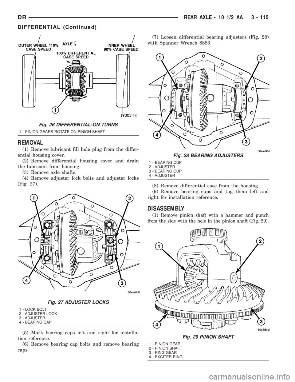
(4) Remove adjuster lock bolts and adjuster locks
(Fig. 27).
(5) Mark bearing caps left and right for installa-
tion reference.
(6) Remove bearing cap bolts and remove bearing
caps.(7) Loosen differential bearing adjusters (Fig. 28)
with Spanner Wrench 8883.
(8) Remove differential case from the housing.
(9) Remove bearing cups and tag them left and
right for installation reference.
DISASSEMBLY
(1)Remove pinion shaft with a hammer and punch
from the side with the hole in the pinion shaft (Fig. 29).
Fig. 26 DIFFERENTIAL-ON TURNS
1 - PINION GEARS ROTATE ON PINION SHAFT
Fig. 27 ADJUSTER LOCKS
1 - LOCK BOLT
2 - ADJUSTER LOCK
3 - ADJUSTER
4 - BEARING CAP
Fig. 28 BEARING ADJUSTERS
1 - BEARING CUP
2 - ADJUSTER
3 - BEARING CUP
4 - ADJUSTER
Fig. 29 PINION SHAFT
1 - PINION GEAR
2 - PINION SHAFT
3 - RING GEAR
4 - EXCITER RING
DRREAR AXLE - 10 1/2 AA 3 - 115
DIFFERENTIAL (Continued)
Page 189 of 2895
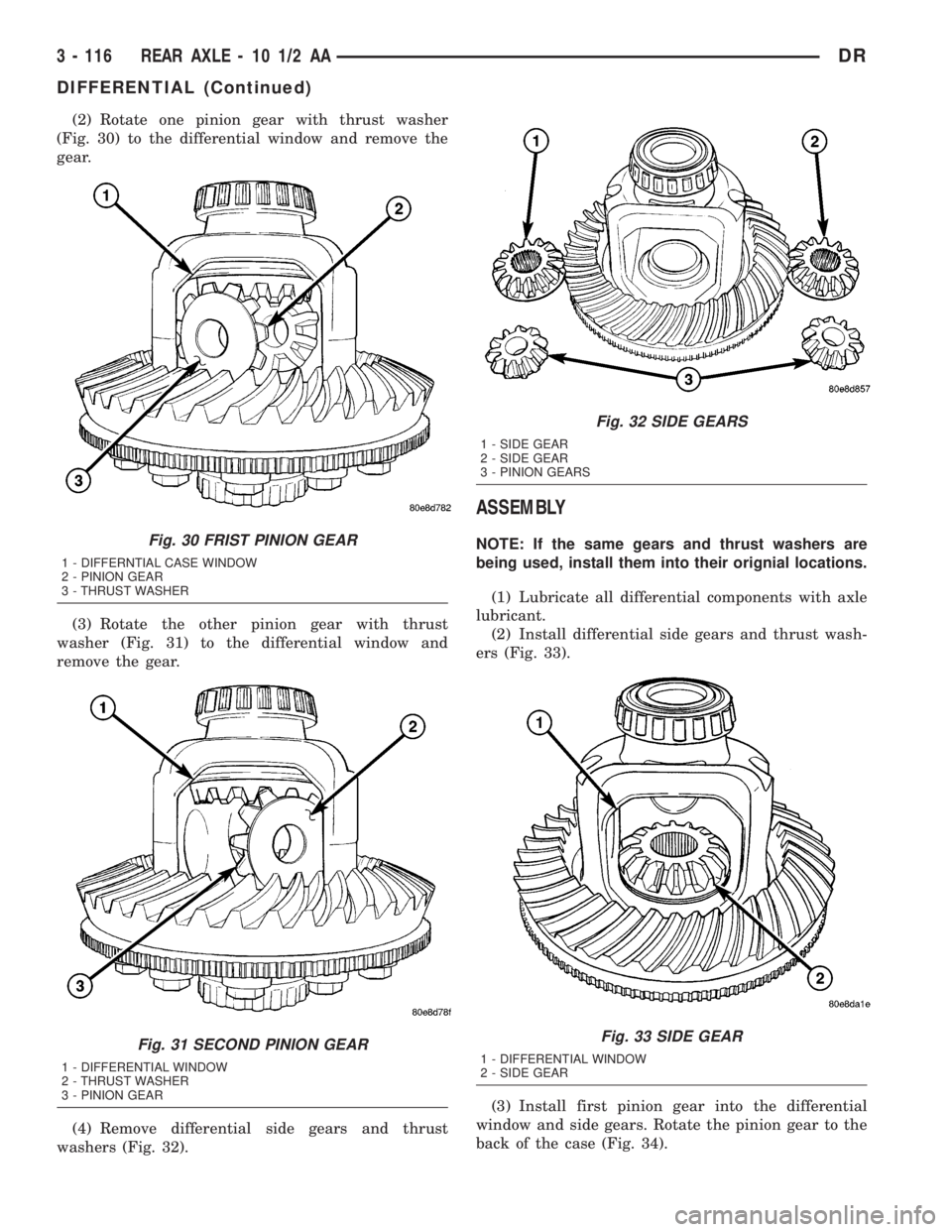
(2) Rotate one pinion gear with thrust washer
(Fig. 30) to the differential window and remove the
gear.
(3) Rotate the other pinion gear with thrust
washer (Fig. 31) to the differential window and
remove the gear.
(4) Remove differential side gears and thrust
washers (Fig. 32).
ASSEMBLY
NOTE: If the same gears and thrust washers are
being used, install them into their orignial locations.
(1) Lubricate all differential components with axle
lubricant.
(2) Install differential side gears and thrust wash-
ers (Fig. 33).
(3) Install first pinion gear into the differential
window and side gears. Rotate the pinion gear to the
back of the case (Fig. 34).Fig. 30 FRIST PINION GEAR
1 - DIFFERNTIAL CASE WINDOW
2 - PINION GEAR
3 - THRUST WASHER
Fig. 31 SECOND PINION GEAR
1 - DIFFERENTIAL WINDOW
2 - THRUST WASHER
3 - PINION GEAR
Fig. 32 SIDE GEARS
1 - SIDE GEAR
2 - SIDE GEAR
3 - PINION GEARS
Fig. 33 SIDE GEAR
1 - DIFFERENTIAL WINDOW
2 - SIDE GEAR
3 - 116 REAR AXLE - 10 1/2 AADR
DIFFERENTIAL (Continued)
Page 190 of 2895
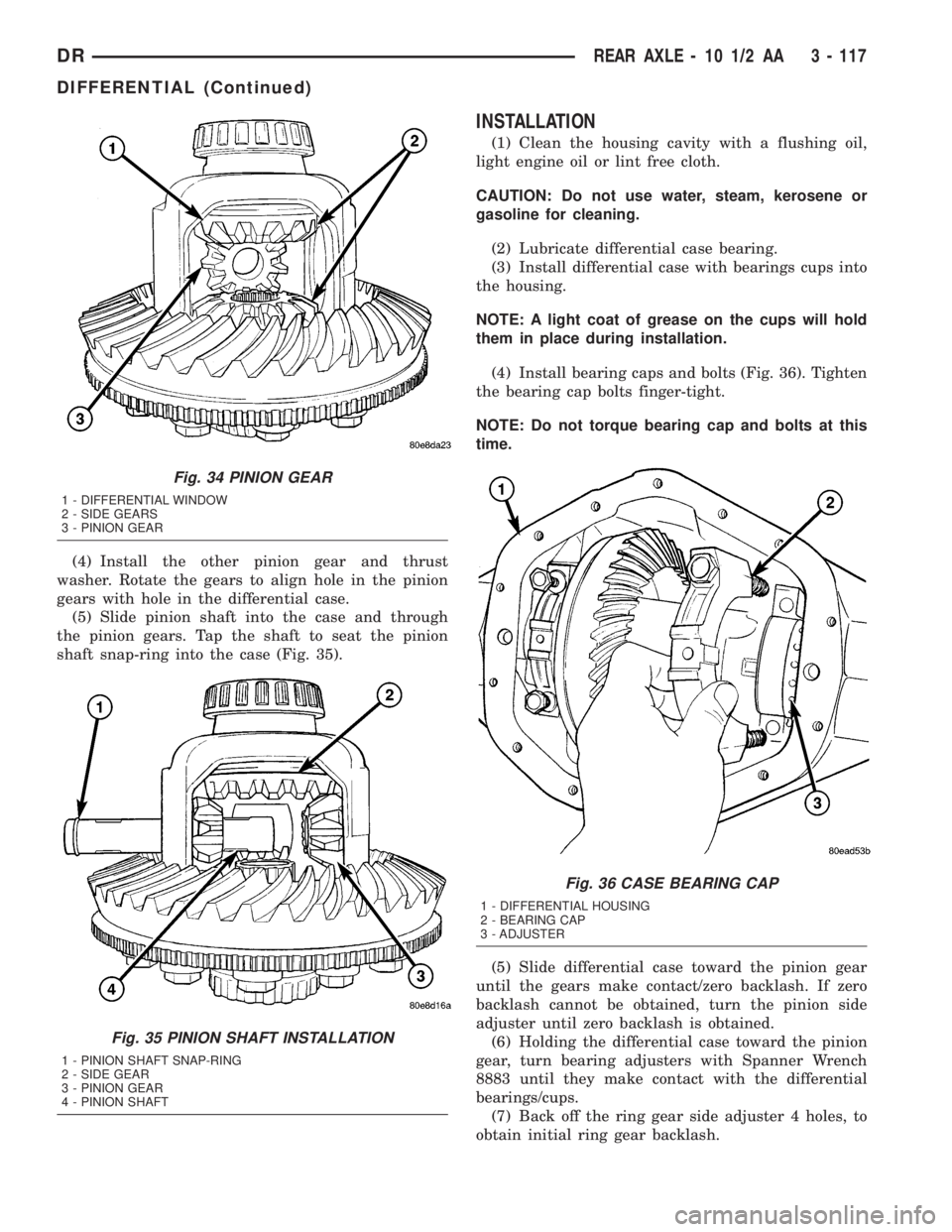
(4) Install the other pinion gear and thrust
washer. Rotate the gears to align hole in the pinion
gears with hole in the differential case.
(5) Slide pinion shaft into the case and through
the pinion gears. Tap the shaft to seat the pinion
shaft snap-ring into the case (Fig. 35).
INSTALLATION
(1) Clean the housing cavity with a flushing oil,
light engine oil or lint free cloth.
CAUTION: Do not use water, steam, kerosene or
gasoline for cleaning.
(2) Lubricate differential case bearing.
(3) Install differential case with bearings cups into
the housing.
NOTE: A light coat of grease on the cups will hold
them in place during installation.
(4) Install bearing caps and bolts (Fig. 36). Tighten
the bearing cap bolts finger-tight.
NOTE: Do not torque bearing cap and bolts at this
time.
(5) Slide differential case toward the pinion gear
until the gears make contact/zero backlash. If zero
backlash cannot be obtained, turn the pinion side
adjuster until zero backlash is obtained.
(6) Holding the differential case toward the pinion
gear, turn bearing adjusters with Spanner Wrench
8883 until they make contact with the differential
bearings/cups.
(7) Back off the ring gear side adjuster 4 holes, to
obtain initial ring gear backlash.
Fig. 34 PINION GEAR
1 - DIFFERENTIAL WINDOW
2 - SIDE GEARS
3 - PINION GEAR
Fig. 35 PINION SHAFT INSTALLATION
1 - PINION SHAFT SNAP-RING
2 - SIDE GEAR
3 - PINION GEAR
4 - PINION SHAFT
Fig. 36 CASE BEARING CAP
1 - DIFFERENTIAL HOUSING
2 - BEARING CAP
3 - ADJUSTER
DRREAR AXLE - 10 1/2 AA 3 - 117
DIFFERENTIAL (Continued)