wiring DODGE RAM 2003 Service Repair Manual
[x] Cancel search | Manufacturer: DODGE, Model Year: 2003, Model line: RAM, Model: DODGE RAM 2003Pages: 2895, PDF Size: 83.15 MB
Page 2559 of 2895
²A flashing operating mode LED for the desired
gear indicates that a shift to that position has been
requested, but all of the driver controllable conditions
have not been met. This is in an attempt to notify
the driver that the transmission needs to be put into
NEUTRAL, the vehicle speed is too great, or some
other condition outlined (other than a diagnostic fail-
ure that would prevent this shift) elsewhere (Refer to
8 - ELECTRICAL/ELECTRONIC CONTROL MOD-
ULES/TRANSFER CASE CONTROL MODULE -
OPERATION) is not met. Note that this flashing will
continue indefinitely until the conditions are eventu-
ally met, or the selector switch position is changed,
or if diagnostic routines no longer allow the
requested shift.
²If the driver attempts to make a shift into trans-
fer case NEUTRAL, and any of the driver controlla-
ble conditions are not met, the request will be
ignored until all of the conditions are met or until
the NEUTRAL select button is released. Additionally
the neutral lamp will flash, or begin to flash while
the button is depressed and operator controllable
conditions are not being met. All of the LED's except
the Neutral will flash if any of the operator control-
lable conditions for shifting are not met while the
Neutral button is depressed. This9toggle9type of fea-
ture is necessary because the TCCM would interpret
another request immediately after the shift into
transfer case NEUTRAL has completed.
²No LED's illuminated indicate a fault in the
transfer case control system.
SHIFT MOTOR
DESCRIPTION
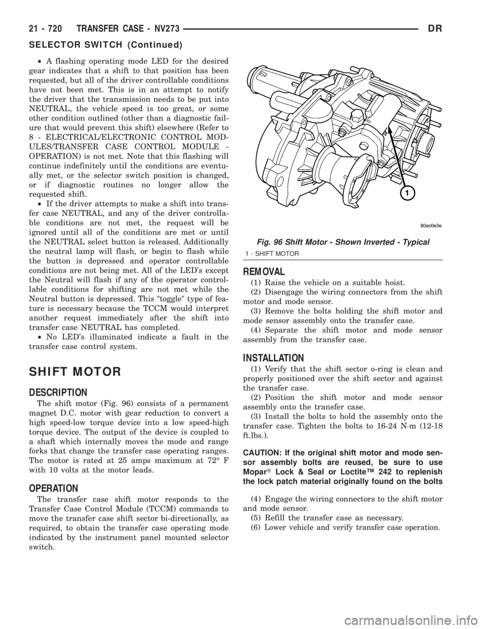
The shift motor (Fig. 96) consists of a permanent
magnet D.C. motor with gear reduction to convert a
high speed-low torque device into a low speed-high
torque device. The output of the device is coupled to
a shaft which internally moves the mode and range
forks that change the transfer case operating ranges.
The motor is rated at 25 amps maximum at 72É F
with 10 volts at the motor leads.
OPERATION
The transfer case shift motor responds to the
Transfer Case Control Module (TCCM) commands to
move the transfer case shift sector bi-directionally, as
required, to obtain the transfer case operating mode
indicated by the instrument panel mounted selector
switch.
REMOVAL
(1) Raise the vehicle on a suitable hoist.
(2) Disengage the wiring connectors from the shift
motor and mode sensor.
(3) Remove the bolts holding the shift motor and
mode sensor assembly onto the transfer case.
(4) Separate the shift motor and mode sensor
assembly from the transfer case.
INSTALLATION
(1) Verify that the shift sector o-ring is clean and
properly positioned over the shift sector and against
the transfer case.
(2) Position the shift motor and mode sensor
assembly onto the transfer case.
(3) Install the bolts to hold the assembly onto the
transfer case. Tighten the bolts to 16-24 N´m (12-18
ft.lbs.).
CAUTION: If the original shift motor and mode sen-
sor assembly bolts are reused, be sure to use
MoparTLock & Seal or LoctiteŸ 242 to replenish
the lock patch material originally found on the bolts
(4) Engage the wiring connectors to the shift motor
and mode sensor.
(5) Refill the transfer case as necessary.
(6) Lower vehicle and verify transfer case operation.
Fig. 96 Shift Motor - Shown Inverted - Typical
1 - SHIFT MOTOR
21 - 720 TRANSFER CASE - NV273DR
SELECTOR SWITCH (Continued)
Page 2576 of 2895
BODY
TABLE OF CONTENTS
page page
BODY
WARNING
SAFETY PRECAUTIONS AND WARNINGS . . . 1
DIAGNOSIS AND TESTING
DIAGNOSIS AND TESTING - WATER LEAKS . 1
DIAGNOSIS AND TESTING - WIND NOISE . . . 2
STANDARD PROCEDURE
STANDARD PROCEDURE - BODY
LUBRICATION.........................3
STANDARD PROCEDURE - HEAT STAKING . . 3
STANDARD PROCEDURE - PLASTIC BODY
PANEL REPAIR........................3
STANDARD PROCEDURE - BUZZ, SQUEAK
& RATTLE...........................11
SPECIFICATIONS - TORQUE..............12SPECIAL TOOLS
BODY..............................14
TAILGATE..............................15
DOOR - FRONT.........................18
DOORS - REAR.........................28
EXTERIOR.............................36
HOOD.................................46
INSTRUMENT PANEL.....................50
INTERIOR..............................63
PAINT.................................74
SEATS................................76
STATIONARY GLASS.....................86
WEATHERSTRIP/SEALS...................91
BODY STRUCTURE......................95
BODY
WARNING
SAFETY PRECAUTIONS AND WARNINGS
WARNING: USE AN OSHA APPROVED BREATHING
FILTER WHEN SPRAYING PAINT OR SOLVENTS IN
A CONFINED AREA. PERSONAL INJURY CAN
RESULT.
²AVOID PROLONGED SKIN CONTACT WITH
PETROLEUM OR ALCOHOL ± BASED CLEANING
SOLVENTS. PERSONAL INJURY CAN RESULT.
²DO NOT STAND UNDER A HOISTED VEHICLE
THAT IS NOT PROPERLY SUPPORTED ON SAFETY
STANDS. PERSONAL INJURY CAN RESULT.
CAUTION: When holes must be drilled or punched
in an inner body panel, verify depth of space to the
outer body panel, electrical wiring, or other compo-
nents. Damage to vehicle can result.
²Do not weld exterior panels unless combustible
material on the interior of vehicle is removed from
the repair area. Fire or hazardous conditions, can
result.
²Always have a fire extinguisher ready for use
when welding.
²Disconnect the negative (-) cable clamp from
the battery when servicing electrical components
that are live when the ignition is OFF. Damage to
electrical system can result.²Do not use abrasive chemicals or compounds
on painted surfaces. Damage to finish can result.
²Do not use harsh alkaline based cleaning sol-
vents on painted or upholstered surfaces. Damage
to finish or color can result.
²Do not hammer or pound on plastic trim panel
when servicing interior trim. Plastic panels can
break.
DIAGNOSIS AND TESTING
DIAGNOSIS AND TESTING - WATER LEAKS
Water leaks can be caused by poor sealing,
improper body component alignment, body seam
porosity, missing plugs, or blocked drain holes. Cen-
trifugal and gravitational force can cause water to
drip from a location away from the actual leak point,
making leak detection difficult. All body sealing
points should be water tight in normal wet-driving
conditions. Water flowing downward from the front of
the vehicle should not enter the passenger or luggage
compartment. Moving sealing surfaces will not
always seal water tight under all conditions. At
times, side glass or door seals will allow water to
enter the passenger compartment during high pres-
sure washing or hard driving rain (severe) condi-
tions. Overcompensating on door or glass
adjustments to stop a water leak that occurs under
severe conditions can cause premature seal wear and
excessive closing or latching effort. After completing
a repair, water test vehicle to verify leak has stopped
before returning vehicle to use.
DRBODY 23 - 1
Page 2579 of 2895
Adhesion Promoter/Surface Modifier:
Adhesion Promoters/Surface Modifiers are required
for certain plastics. All three categories may have
plastics that require the use of adhesion promoter/
surface modifiers. Always follow repair material man-
ufacturer's plastic identification and repair
procedures.
SAFETY PRECAUTION AND WARNINGS
WARNING:
²EYE PROTECTION SHOULD BE USED WHEN
SERVICING COMPONENTS. PERSONAL INJURY
CAN RESULT.
²USE AN OSHA APPROVED BREATHING MASK
WHEN MIXING EPOXY, GRINDING, AND SPRAYING
PAINT OR SOLVENTS IN A CONFINED AREA. PER-
SONAL INJURY CAN RESULT.²AVOID PROLONGED SKIN CONTACT WITH
RESIN, PETROLEUM, OR ALCOHOL BASED SOL-
VENTS. PERSONAL INJURY CAN RESULT.
²DO NOT VENTURE UNDER A HOISTED VEHI-
CLE THAT IS NOT PROPERLY SUPPORTED ON
SAFETY STANDS. PERSONAL INJURY CAN
RESULT.
NOTE:
²When holes must be drilled or cut in body pan-
els, verify locations of internal body components
and electrical wiring. Damage to vehicle can result.
²Do not use abrasive chemicals or compounds
on undamaged painted surfaces around repair
areas. Damage to finish can result.
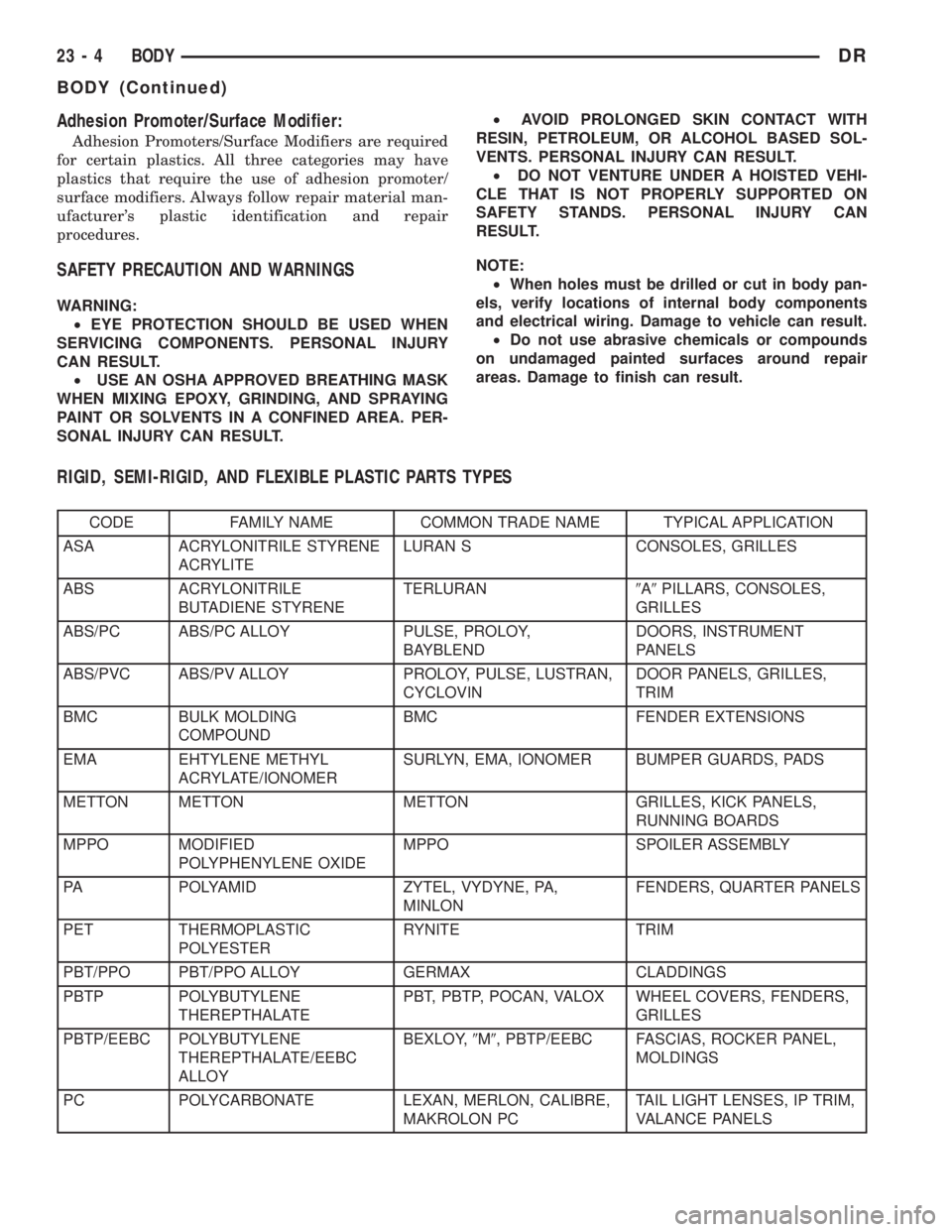
RIGID, SEMI-RIGID, AND FLEXIBLE PLASTIC PARTS TYPES
CODE FAMILY NAME COMMON TRADE NAME TYPICAL APPLICATION
ASA ACRYLONITRILE STYRENE
ACRYLITELURAN S CONSOLES, GRILLES
ABS ACRYLONITRILE
BUTADIENE STYRENETERLURAN9A9PILLARS, CONSOLES,
GRILLES
ABS/PC ABS/PC ALLOY PULSE, PROLOY,
BAYBLENDDOORS, INSTRUMENT
PANELS
ABS/PVC ABS/PV ALLOY PROLOY, PULSE, LUSTRAN,
CYCLOVINDOOR PANELS, GRILLES,
TRIM
BMC BULK MOLDING
COMPOUNDBMC FENDER EXTENSIONS
EMA EHTYLENE METHYL
ACRYLATE/IONOMERSURLYN, EMA, IONOMER BUMPER GUARDS, PADS
METTON METTON METTON GRILLES, KICK PANELS,
RUNNING BOARDS
MPPO MODIFIED
POLYPHENYLENE OXIDEMPPO SPOILER ASSEMBLY
PA POLYAMID ZYTEL, VYDYNE, PA,
MINLONFENDERS, QUARTER PANELS
PET THERMOPLASTIC
POLYESTERRYNITE TRIM
PBT/PPO PBT/PPO ALLOY GERMAX CLADDINGS
PBTP POLYBUTYLENE
THEREPTHALATEPBT, PBTP, POCAN, VALOX WHEEL COVERS, FENDERS,
GRILLES
PBTP/EEBC POLYBUTYLENE
THEREPTHALATE/EEBC
ALLOYBEXLOY,9M9, PBTP/EEBC FASCIAS, ROCKER PANEL,
MOLDINGS
PC POLYCARBONATE LEXAN, MERLON, CALIBRE,
MAKROLON PCTAIL LIGHT LENSES, IP TRIM,
VALANCE PANELS
23 - 4 BODYDR
BODY (Continued)
Page 2586 of 2895
STANDARD PROCEDURE - BUZZ, SQUEAK &
RATTLE
Buzz, Squeak & Rattles (BSR) may be caused by
any one or more of the following and may be cor-
rected as indicated:
²Loose fasteners should be tightened to specifica-
tions.
²Damaged or missing clips should be replaced.
²Damaged trim panels should be replaced.²Incorrectly installed trim panels should be rein-
stalled properly.
Many BSR complaints such as loose trim, can be
serviced using the MopartParts BSR Noise Reduc-
tion Kit. This kit contains various tapes including
foam, flock and anti-squeak used to eliminate noises
caused by metal, plastic and vinyl components. Long
life lubricants and greases can also be used on a vari-
ety of components. Refer to the Buzz, Squeak & Rat-
tle Kit table for material contents and usage.
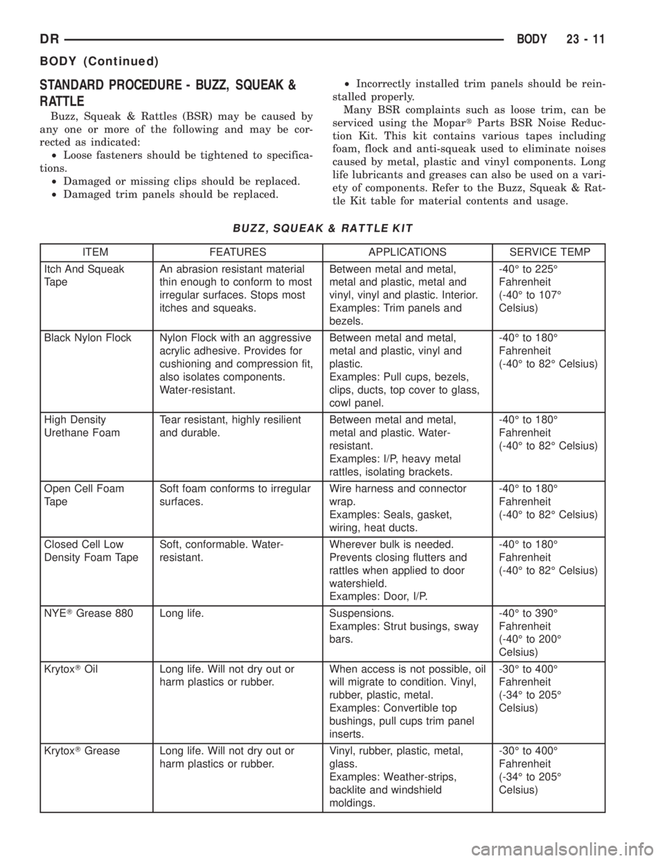
BUZZ, SQUEAK & RATTLE KIT
ITEM FEATURES APPLICATIONS SERVICE TEMP
Itch And Squeak
TapeAn abrasion resistant material
thin enough to conform to most
irregular surfaces. Stops most
itches and squeaks.Between metal and metal,
metal and plastic, metal and
vinyl, vinyl and plastic. Interior.
Examples: Trim panels and
bezels.-40É to 225É
Fahrenheit
(-40É to 107É
Celsius)
Black Nylon Flock Nylon Flock with an aggressive
acrylic adhesive. Provides for
cushioning and compression fit,
also isolates components.
Water-resistant.Between metal and metal,
metal and plastic, vinyl and
plastic.
Examples: Pull cups, bezels,
clips, ducts, top cover to glass,
cowl panel.-40É to 180É
Fahrenheit
(-40É to 82É Celsius)
High Density
Urethane FoamTear resistant, highly resilient
and durable.Between metal and metal,
metal and plastic. Water-
resistant.
Examples: I/P, heavy metal
rattles, isolating brackets.-40É to 180É
Fahrenheit
(-40É to 82É Celsius)
Open Cell Foam
TapeSoft foam conforms to irregular
surfaces.Wire harness and connector
wrap.
Examples: Seals, gasket,
wiring, heat ducts.-40É to 180É
Fahrenheit
(-40É to 82É Celsius)
Closed Cell Low
Density Foam TapeSoft, conformable. Water-
resistant.Wherever bulk is needed.
Prevents closing flutters and
rattles when applied to door
watershield.
Examples: Door, I/P.-40É to 180É
Fahrenheit
(-40É to 82É Celsius)
NYETGrease 880 Long life. Suspensions.
Examples: Strut busings, sway
bars.-40É to 390É
Fahrenheit
(-40É to 200É
Celsius)
KrytoxTOil Long life. Will not dry out or
harm plastics or rubber.When access is not possible, oil
will migrate to condition. Vinyl,
rubber, plastic, metal.
Examples: Convertible top
bushings, pull cups trim panel
inserts.-30É to 400É
Fahrenheit
(-34É to 205É
Celsius)
KrytoxTGrease Long life. Will not dry out or
harm plastics or rubber.Vinyl, rubber, plastic, metal,
glass.
Examples: Weather-strips,
backlite and windshield
moldings.-30É to 400É
Fahrenheit
(-34É to 205É
Celsius)
DRBODY 23 - 11
BODY (Continued)
Page 2697 of 2895
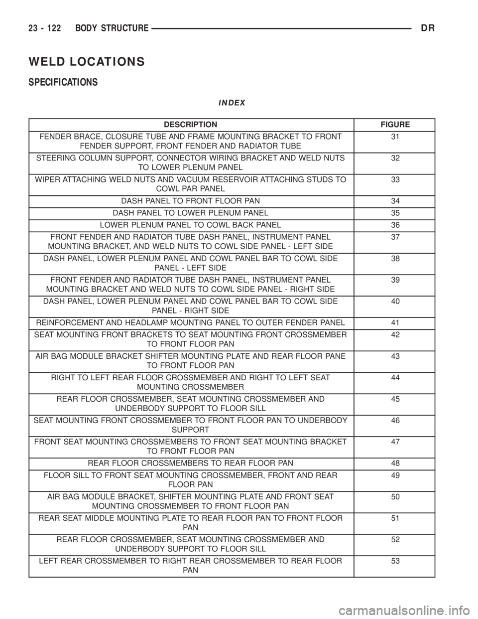
WELD LOCATIONS
SPECIFICATIONS
INDEX
DESCRIPTION FIGURE
FENDER BRACE, CLOSURE TUBE AND FRAME MOUNTING BRACKET TO FRONT
FENDER SUPPORT, FRONT FENDER AND RADIATOR TUBE31
STEERING COLUMN SUPPORT, CONNECTOR WIRING BRACKET AND WELD NUTS
TO LOWER PLENUM PANEL32
WIPER ATTACHING WELD NUTS AND VACUUM RESERVOIR ATTACHING STUDS TO
COWL PAR PANEL33
DASH PANEL TO FRONT FLOOR PAN 34
DASH PANEL TO LOWER PLENUM PANEL 35
LOWER PLENUM PANEL TO COWL BACK PANEL 36
FRONT FENDER AND RADIATOR TUBE DASH PANEL, INSTRUMENT PANEL
MOUNTING BRACKET, AND WELD NUTS TO COWL SIDE PANEL - LEFT SIDE37
DASH PANEL, LOWER PLENUM PANEL AND COWL PANEL BAR TO COWL SIDE
PANEL - LEFT SIDE38
FRONT FENDER AND RADIATOR TUBE DASH PANEL, INSTRUMENT PANEL
MOUNTING BRACKET AND WELD NUTS TO COWL SIDE PANEL - RIGHT SIDE39
DASH PANEL, LOWER PLENUM PANEL AND COWL PANEL BAR TO COWL SIDE
PANEL - RIGHT SIDE40
REINFORCEMENT AND HEADLAMP MOUNTING PANEL TO OUTER FENDER PANEL 41
SEAT MOUNTING FRONT BRACKETS TO SEAT MOUNTING FRONT CROSSMEMBER
TO FRONT FLOOR PAN42
AIR BAG MODULE BRACKET SHIFTER MOUNTING PLATE AND REAR FLOOR PANE
TO FRONT FLOOR PAN43
RIGHT TO LEFT REAR FLOOR CROSSMEMBER AND RIGHT TO LEFT SEAT
MOUNTING CROSSMEMBER44
REAR FLOOR CROSSMEMBER, SEAT MOUNTING CROSSMEMBER AND
UNDERBODY SUPPORT TO FLOOR SILL45
SEAT MOUNTING FRONT CROSSMEMBER TO FRONT FLOOR PAN TO UNDERBODY
SUPPORT46
FRONT SEAT MOUNTING CROSSMEMBERS TO FRONT SEAT MOUNTING BRACKET
TO FRONT FLOOR PAN47
REAR FLOOR CROSSMEMBERS TO REAR FLOOR PAN 48
FLOOR SILL TO FRONT SEAT MOUNTING CROSSMEMBER, FRONT AND REAR
FLOOR PAN49
AIR BAG MODULE BRACKET, SHIFTER MOUNTING PLATE AND FRONT SEAT
MOUNTING CROSSMEMBER TO FRONT FLOOR PAN50
REAR SEAT MIDDLE MOUNTING PLATE TO REAR FLOOR PAN TO FRONT FLOOR
PA N51
REAR FLOOR CROSSMEMBER, SEAT MOUNTING CROSSMEMBER AND
UNDERBODY SUPPORT TO FLOOR SILL52
LEFT REAR CROSSMEMBER TO RIGHT REAR CROSSMEMBER TO REAR FLOOR
PA N53
23 - 122 BODY STRUCTUREDR
Page 2782 of 2895
STANDARD PROCEDURE - DIODE
REPLACEMENT
(1) Disconnect the battery negative cable and iso-
late it. If vehicle has a dual batterys remove both
negative cables.
(2) Locate the diode in the harness, and remove
the protective covering.
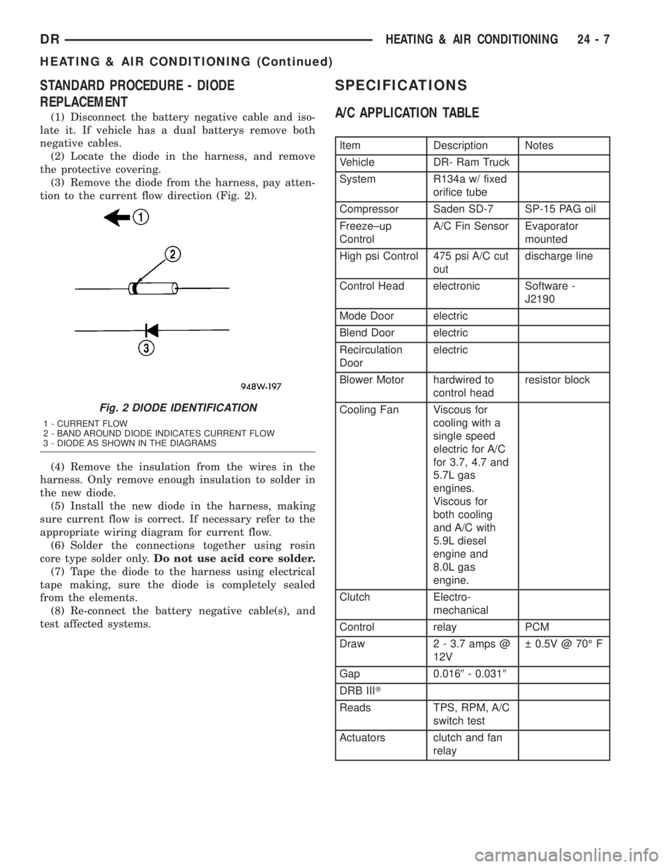
(3) Remove the diode from the harness, pay atten-
tion to the current flow direction (Fig. 2).
(4) Remove the insulation from the wires in the
harness. Only remove enough insulation to solder in
the new diode.
(5) Install the new diode in the harness, making
sure current flow is correct. If necessary refer to the
appropriate wiring diagram for current flow.
(6) Solder the connections together using rosin
core type solder only.Do not use acid core solder.
(7) Tape the diode to the harness using electrical
tape making, sure the diode is completely sealed
from the elements.
(8) Re-connect the battery negative cable(s), and
test affected systems.
SPECIFICATIONS
A/C APPLICATION TABLE
Item Description Notes
Vehicle DR- Ram Truck
System R134a w/ fixed
orifice tube
Compressor Saden SD-7 SP-15 PAG oil
Freeze±up
ControlA/C Fin Sensor Evaporator
mounted
High psi Control 475 psi A/C cut
outdischarge line
Control Head electronic Software -
J2190
Mode Door electric
Blend Door electric
Recirculation
Doorelectric
Blower Motor hardwired to
control headresistor block
Cooling Fan Viscous for
cooling with a
single speed
electric for A/C
for 3.7, 4.7 and
5.7L gas
engines.
Viscous for
both cooling
and A/C with
5.9L diesel
engine and
8.0L gas
engine.
Clutch Electro-
mechanical
Control relay PCM
Draw 2 - 3.7 amps @
12V 0.5V @ 70É F
Gap 0.0169- 0.0319
DRB IIIT
Reads TPS, RPM, A/C
switch test
Actuators clutch and fan
relay
Fig. 2 DIODE IDENTIFICATION
1 - CURRENT FLOW
2 - BAND AROUND DIODE INDICATES CURRENT FLOW
3 - DIODE AS SHOWN IN THE DIAGRAMS
DRHEATING & AIR CONDITIONING 24 - 7
HEATING & AIR CONDITIONING (Continued)
Page 2785 of 2895
seconds. Refer to Electronic Control Modules for
more information on the JTEC controls.
DIAGNOSIS AND TESTING - A/C COMPRESSOR
CLUTCH COIL
For circuit descriptions and diagrams, (Refer to
Appropriate Wiring Information). The battery must
be fully-charged before performing the following
tests. Refer to Battery for more information.
(1) Connect an ammeter (0 to 10 ampere scale) in
series with the clutch coil terminal. Use a voltmeter
(0 to 20 volt scale) with clip-type leads for measuring
the voltage across the battery and the compressor
clutch coil.
(2) With the A/C Heater mode control switch in
any A/C mode, and the blower motor switch in the
lowest speed position, start the engine and run it at
normal idle.
(3) The compressor clutch coil voltage should read
within 0.2 volts of the battery voltage. If there is
voltage at the clutch coil, but the reading is not
within 0.2 volts of the battery voltage, test the clutch
coil feed circuit for excessive voltage drop and repair
as required. If there is no voltage reading at the
clutch coil, use a DRB IIItscan tool and (Refer to
Appropriate Diagnostic Information) for testing of the
compressor clutch circuit and PCM control. The fol-
lowing components must be checked and repaired as
required before you can complete testing of the clutch
coil:
²Fuses in the junction block and the Power Dis-
tribution Center (PDC)
²A/C heater mode control switch
²Compressor clutch relay
²A/C high pressure transducer switch²JTEC
(4) The compressor clutch coil is acceptable if the
current draw measured at the clutch coil is 2.0 to 3.9
amperes with the electrical system voltage at 11.5 to
12.5 volts. This should only be checked with the work
area temperature at 21É C (70É F). If system voltage
is more than 12.5 volts, add electrical loads by turn-
ing on electrical accessories until the system voltage
drops below 12.5 volts.
(a) If the clutch coil current reading is four
amperes or more, the coil is shorted and should be
replaced.
(b) If the clutch coil current reading is zero, the
coil is open and should be replaced.
STANDARD PROCEDURE - A/C COMPRESSOR
CLUTCH BREAK-IN
After a new compressor clutch has been installed,
cycle the compressor clutch approximately twenty
times (five seconds on, then five seconds off). During
this procedure, set the A/C Heater control to the
Recirculation Mode, the blower motor switch in the
highest speed position, and the engine speed at 1500
to 2000 rpm. This procedure (burnishing) will seat
the opposing friction surfaces and provide a higher
compressor clutch torque capability.
REMOVAL
The refrigerant system can remain fully-charged
during compressor clutch, rotor, or coil replacement.
The compressor clutch can be serviced in the vehicle.
(1) Disconnect and isolate the battery negative
cable.
(2) Remove the serpentine drive belt(Refer to 7 -
COOLING/ACCESSORY DRIVE/DRIVE BELTS -
REMOVAL).
(3) Unplug the compressor clutch coil wire harness
connector.
(4) Remove the bolts that secure the compressor to
the mounting bracket.
(5) Remove the compressor from the mounting
bracket. Support the compressor in the engine com-
partment while servicing the clutch.
(6) Insert the two pins of the spanner wrench
(Special Tool C-4489 or equivalent) into the holes of
the clutch plate. Hold the clutch plate stationary and
remove the hex nut (Fig. 2).
(7) Remove the clutch plate.
(8) Remove the compressor clutch shims.
(9) Remove the external front housing snap ring
with snap ring pliers (Fig. 3).
(10)
Install the lip of the rotor puller (Special Tool
C-6141-1 or equivalent) into the snap ring groove
exposed in the previous step, and install the shaft pro-
tector (Special Tool C-6141-2 or equivalent) (Fig. 4).
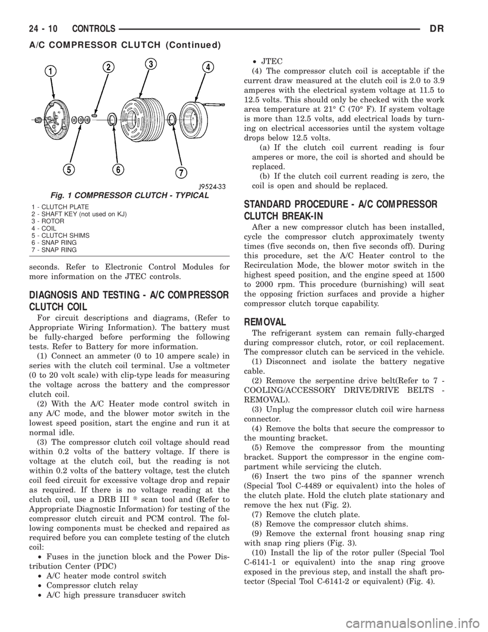
Fig. 1 COMPRESSOR CLUTCH - TYPICAL
1 - CLUTCH PLATE
2 - SHAFT KEY (not used on KJ)
3 - ROTOR
4 - COIL
5 - CLUTCH SHIMS
6 - SNAP RING
7 - SNAP RING
24 - 10 CONTROLSDR
A/C COMPRESSOR CLUTCH (Continued)
Page 2788 of 2895
NOTE: The air gap is determined by the spacer
shims. When installing an original, or a new clutch
assembly, try the original shims first. When install-
ing a new clutch onto a compressor that previously
did not have a clutch, use a 1.0, 0.50, and 0.13 mil-
limeter (0.040, 0.020, and 0.005 inch) shims from the
new clutch hardware package that is provided with
the new clutch.
(9) To complete the procedure, (Refer to 24 -
HEATING & AIR CONDITIONING/PLUMBING/A/C
COMPRESSOR - INSTALLATION).
A/C COMPRESSOR CLUTCH
RELAY
DESCRIPTION
The compressor clutch relay is a International
Standards Organization (ISO) micro-relay. The termi-
nal designations and functions are the same as a con-
ventional ISO relay. However, the micro-relay
terminal orientation (footprint) is different, the cur-
rent capacity is lower, and the relay case dimensions
are smaller than those of the conventional ISO relay.
The compressor clutch relay is located in the Power
Distribution Center (PDC) in the engine compart-
ment. Refer to the PDC label for relay identification
and location.
OPERATION
The compressor clutch relay is a electromechanical
device that switches battery current to the compres-
sor clutch coil when the Powertrain Control Module
(PCM) grounds the coil side of the relay. The PCM
responds to inputs from the A/C Heater mode control
switch, the A/C low pressure switch, and the A/C
high pressure switch. (Refer to 24 - HEATING & AIR
CONDITIONING/CONTROLS/A/C COMPRESSOR
CLUTCH RELAY - DIAGNOSIS AND TESTING)
The compressor clutch relay cannot be repaired
and, if faulty or damaged, it must be replaced.
DIAGNOSIS AND TESTING - COMPRESSOR
CLUTCH RELAY
RELAY TEST
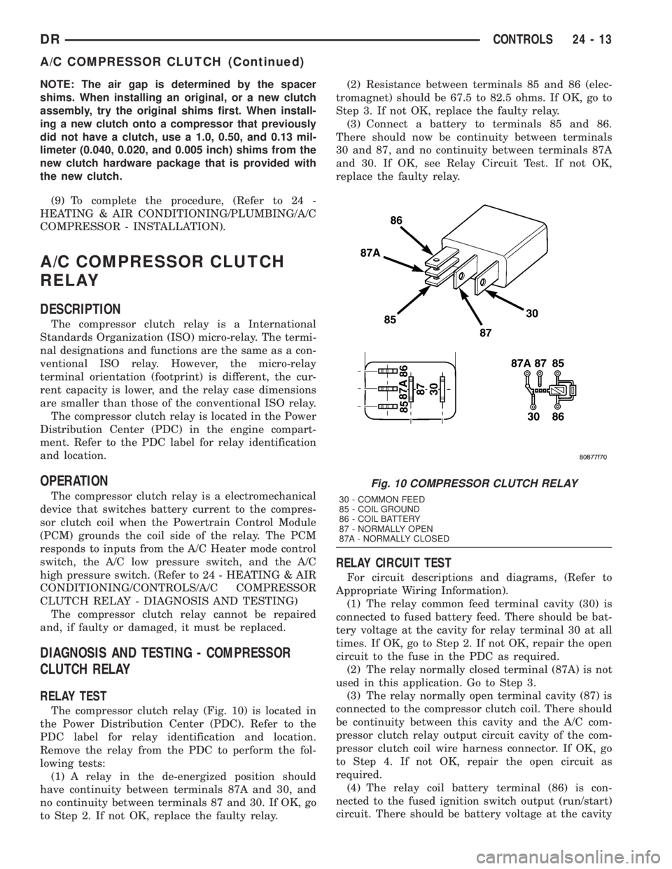
The compressor clutch relay (Fig. 10) is located in
the Power Distribution Center (PDC). Refer to the
PDC label for relay identification and location.
Remove the relay from the PDC to perform the fol-
lowing tests:
(1) A relay in the de-energized position should
have continuity between terminals 87A and 30, and
no continuity between terminals 87 and 30. If OK, go
to Step 2. If not OK, replace the faulty relay.(2) Resistance between terminals 85 and 86 (elec-
tromagnet) should be 67.5 to 82.5 ohms. If OK, go to
Step 3. If not OK, replace the faulty relay.
(3) Connect a battery to terminals 85 and 86.
There should now be continuity between terminals
30 and 87, and no continuity between terminals 87A
and 30. If OK, see Relay Circuit Test. If not OK,
replace the faulty relay.
RELAY CIRCUIT TEST
For circuit descriptions and diagrams, (Refer to
Appropriate Wiring Information).
(1) The relay common feed terminal cavity (30) is
connected to fused battery feed. There should be bat-
tery voltage at the cavity for relay terminal 30 at all
times. If OK, go to Step 2. If not OK, repair the open
circuit to the fuse in the PDC as required.
(2) The relay normally closed terminal (87A) is not
used in this application. Go to Step 3.
(3) The relay normally open terminal cavity (87) is
connected to the compressor clutch coil. There should
be continuity between this cavity and the A/C com-
pressor clutch relay output circuit cavity of the com-
pressor clutch coil wire harness connector. If OK, go
to Step 4. If not OK, repair the open circuit as
required.
(4) The relay coil battery terminal (86) is con-
nected to the fused ignition switch output (run/start)
circuit. There should be battery voltage at the cavity
Fig. 10 COMPRESSOR CLUTCH RELAY
30 - COMMON FEED
85 - COIL GROUND
86 - COIL BATTERY
87 - NORMALLY OPEN
87A - NORMALLY CLOSED
DRCONTROLS 24 - 13
A/C COMPRESSOR CLUTCH (Continued)
Page 2793 of 2895
blower. The blower motor switch directs the ground
path through the correct resistor circuit to obtain the
selected speed.
The blower motor resistor cannot be repaired and,
if faulty or damaged, it must be replaced.
DIAGNOSIS AND TESTING - BLOWER MOTOR
RESISTOR
For circuit descriptions and diagrams, (Refer to
Appropriate Wiring Information).
WARNING: ON VEHICLES EQUIPPED WITH AIR-
BAGS, DISABLE THE AIRBAG SYSTEM BEFORE
ATTEMPTING ANY STEERING WHEEL, STEERING
COLUMN, OR INSTRUMENT PANEL COMPONENT
DIAGNOSIS OR SERVICE. DISCONNECT AND ISO-
LATE THE BATTERY NEGATIVE (GROUND) CABLE,
THEN WAIT TWO MINUTES FOR THE AIRBAG SYS-
TEM CAPACITOR TO DISCHARGE BEFORE PER-
FORMING FURTHER DIAGNOSIS OR SERVICE. THIS
IS THE ONLY SURE WAY TO DISABLE THE AIRBAG
SYSTEM. FAILURE TO TAKE THE PROPER PRE-
CAUTIONS COULD RESULT IN AN ACCIDENTAL
AIRBAG DEPLOYMENT AND POSSIBLE PERSONAL
INJURY.
(1) Disconnect and isolate the battery negative
cable.
(2) Reach under the passenger side bottom of the
HVAC unit and unplug the wire harness connector
from the blower motor resistor.
(3) Check for continuity between each of the
blower motor switch input terminals of the resistor
and the resistor output terminal. In each case there
should be continuity. If OK, repair the wire harness
circuits between the blower motor switch and the
blower motor resistor or blower motor relay as
required. If not OK, replace the faulty blower motor
resistor.
REMOVAL
WARNING: ON VEHICLES EQUIPPED WITH AIR-
BAGS, DISABLE THE AIRBAG SYSTEM BEFORE
ATTEMPTING ANY STEERING WHEEL, STEERING
COLUMN, OR INSTRUMENT PANEL COMPONENT
DIAGNOSIS OR SERVICE. DISCONNECT AND ISO-
LATE THE BATTERY NEGATIVE (GROUND) CABLE,
THEN WAIT TWO MINUTES FOR THE AIRBAG SYS-
TEM CAPACITOR TO DISCHARGE BEFORE PER-
FORMING FURTHER DIAGNOSIS OR SERVICE. THIS
IS THE ONLY SURE WAY TO DISABLE THE AIRBAG
SYSTEM. FAILURE TO TAKE THE PROPER PRE-
CAUTIONS COULD RESULT IN AN ACCIDENTAL
AIRBAG DEPLOYMENT AND POSSIBLE PERSONAL
INJURY.(1) Disconnect and isolate the battery negative
cable.
(2) The blower motor resistor is accessable from
the passenger side of the HVAC unit and is located
on the bottom of the HVAC unit.
(3) Pull out the lock on the blower motor resistor
wire harness connector to unlock the connector latch.
(4) Depress the latch on the blower motor resistor
wire harness connector and unplug the connector
from the resistor.
(5) Remove the two screws that secure the resistor
to the HVAC housing.
(6) Remove the resistor from the HVAC housing.
INSTALLATION
(1) Install the new resistor in the HVAC housing.
(2) Install the two screws that secure the resistor
to the HVAC housing and tighten to 2.2 N´m (20 in.
lbs.).
(3) Plug in the blower motor harness connector.
(4) Push in the lock on the blower motor resistor
harness connector.
(5) Close the glove box door.
(6) Connect the battery negative cable.
BLOWER MOTOR SWITCH
DESCRIPTION
The A/C Heater blower motor is controlled by a
four position rotary-type blower motor switch,
mounted in the A/C Heater control panel. The switch
allows the selection of one of four blower motor
speeds, but can only be turned off by selecting the
Off position on the blower motor switch.
OPERATION
The blower motor switch directs the blower motor
ground path through the mode control switch to the
blower motor resistor, or directly to ground, as
required to achieve the selected blower motor speed.
The blower motor switch cannot be repaired and, if
faulty or damaged, the entire A/C Heater control unit
must be replaced.
DIAGNOSIS AND TESTING - BLOWER MOTOR
SWITCH
For circuit descriptions and diagrams, (Refer to
Appropriate Wiring Information).
24 - 18 CONTROLSDR
BLOWER MOTOR RESISTOR BLOCK (Continued)
Page 2801 of 2895
DIAGNOSIS AND TESTING - BLOWER MOTOR
WARNING: ON VEHICLES EQUIPPED WITH AIR-
BAGS, DISABLE THE AIRBAG SYSTEM BEFORE
ATTEMPTING ANY STEERING WHEEL, STEERING
COLUMN, OR INSTRUMENT PANEL COMPONENT
DIAGNOSIS OR SERVICE. DISCONNECT AND ISO-
LATE THE BATTERY NEGATIVE (GROUND) CABLE,
THEN WAIT TWO MINUTES FOR THE AIRBAG SYS-
TEM CAPACITOR TO DISCHARGE BEFORE PER-
FORMING FURTHER DIAGNOSIS OR SERVICE. THIS
IS THE ONLY SURE WAY TO DISABLE THE AIRBAG
SYSTEM. FAILURE TO TAKE THE PROPER PRE-
CAUTIONS COULD RESULT IN AN ACCIDENTAL
AIRBAG DEPLOYMENT AND POSSIBLE PERSONAL
INJURY.
For circuit descriptions and diagrams, (Refer to
Appropriate Wiring Information). Possible causes of
an inoperative blower motor include:
²Faulty fuse
²Faulty blower motor circuit wiring or wire har-
ness connectors
²Faulty blower motor resistor
²Faulty blower motor relay
²Faulty blower motor switch
²Faulty A/C Heater mode control switch
²Faulty blower motor.
Possible causes of the blower motor not operating
in all speeds include:
²Faulty blower motor switch
²Faulty blower motor resistor
²Faulty blower motor circuit wiring or wire har-
ness connectors.
VIBRATION
Possible causes of blower motor vibration include:
²Improper blower motor mounting
²Improper blower wheel mounting
²Blower wheel out of balance or bent
²Blower motor faulty.
NOISE
To verify that the blower is the source of the noise,
unplug the blower motor wire harness connector and
operate the HVAC system. If the noise goes away,
possible causes include:
²Foreign material in the HVAC housing
²Improper blower motor mounting
²Improper blower wheel mounting
²Blower motor faulty.
REMOVAL
WARNING: ON VEHICLES EQUIPPED WITH AIR-
BAGS, DISABLE THE AIRBAG SYSTEM BEFORE
ATTEMPTING ANY STEERING WHEEL, STEERINGCOLUMN, OR INSTRUMENT PANEL COMPONENT
DIAGNOSIS OR SERVICE. DISCONNECT AND ISO-
LATE THE BATTERY NEGATIVE (GROUND) CABLE,
THEN WAIT TWO MINUTES FOR THE AIRBAG SYS-
TEM CAPACITOR TO DISCHARGE BEFORE PER-
FORMING FURTHER DIAGNOSIS OR SERVICE. THIS
IS THE ONLY SURE WAY TO DISABLE THE AIRBAG
SYSTEM. FAILURE TO TAKE THE PROPER PRE-
CAUTIONS COULD RESULT IN AN ACCIDENTAL
AIRBAG DEPLOYMENT AND POSSIBLE PERSONAL
INJURY.
The blower motor is located on the passenger side
of the vehicle under the dash
(1) Disconnect and isolate the battery negative
cable.
(2) Unplug the blower motor wire harness connec-
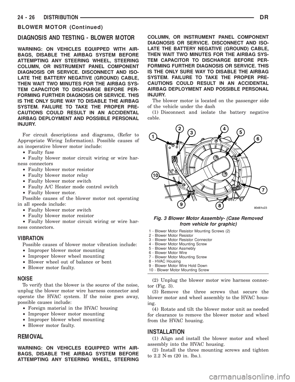
tor (Fig. 3).
(3) Remove the three screws that secure the
blower motor and wheel assembly to the HVAC hous-
ing.
(4) Rotate and tilt the blower motor unit as needed
for clearance to remove the blower motor and wheel
from the HVAC housing.
INSTALLATION
(1) Align and install the blower motor and wheel
assembly into the HVAC housing.
(2) Install the three mounting screws and tighten
to 2.2 N´m (20 in. lbs.).
Fig. 3 Blower Motor Assembly- (Case Removed
from vehicle for graphic)
1 - Blower Motor Resistor Mounting Screws (2)
2 - Blower Motor Resistor
3 - Blower Motor Resistor Connector
4 - Blower Motor Mounting Screw
5 - Blower Motor Assmebly
6 - Blower Motor Wire
7 - Blower Motor Mounting Screw
8 - HVAC Housing
9 - Blower Motor Wire Hold Down
10 - Blower Motor Mounting Screw
24 - 26 DISTRIBUTIONDR
BLOWER MOTOR (Continued)