bushing DODGE RAM 2003 Service User Guide
[x] Cancel search | Manufacturer: DODGE, Model Year: 2003, Model line: RAM, Model: DODGE RAM 2003Pages: 2895, PDF Size: 83.15 MB
Page 58 of 2895
DESCRIPTION N´m Ft. Lbs. In. Lbs.
Stabilizer Link
Stabilizer Bar Nut38 27 Ð
Hub/Bearing
Bolts202 149 Ð
Axle Nut 179 Beginning Torque, Then
Rotate 5 to 10 Times With a
Final Torque of 356132 Beginning Torque, Then
Rotate 5 to 10 Times With a
Final Torque of 263Ð
Tie Rod End
Nut75 55 Ð
NOTE: Suspension components with rubber/ure-
thane bushings should be tightened with the vehi-
cle at normal ride height. It is important to have the
springs supporting the weight of the vehicle when
the fasteners are torqued. If springs are not at their
normal ride position, vehicle ride comfort could be
affected and premature bushing wear may occur.
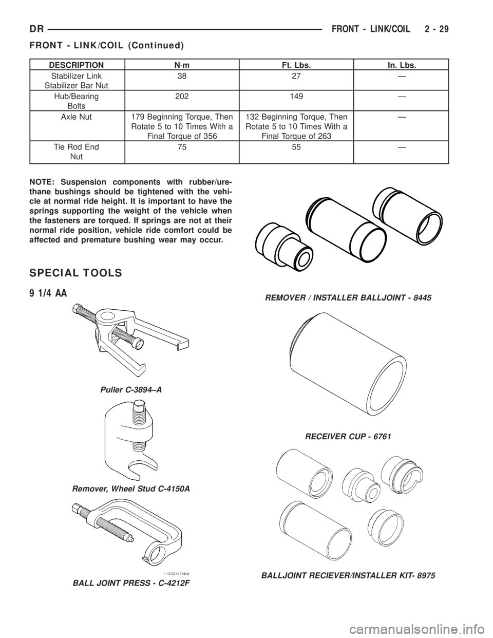
SPECIAL TOOLS
9 1/4 AA
Puller C-3894±A
Remover, Wheel Stud C-4150A
BALL JOINT PRESS - C-4212F
REMOVER / INSTALLER BALLJOINT - 8445
RECEIVER CUP - 6761
BALLJOINT RECIEVER/INSTALLER KIT- 8975
DRFRONT - LINK/COIL 2 - 29
FRONT - LINK/COIL (Continued)
Page 64 of 2895
LOWER SUSPENSION ARM
REMOVAL
(1) Raise and support the vehicle.
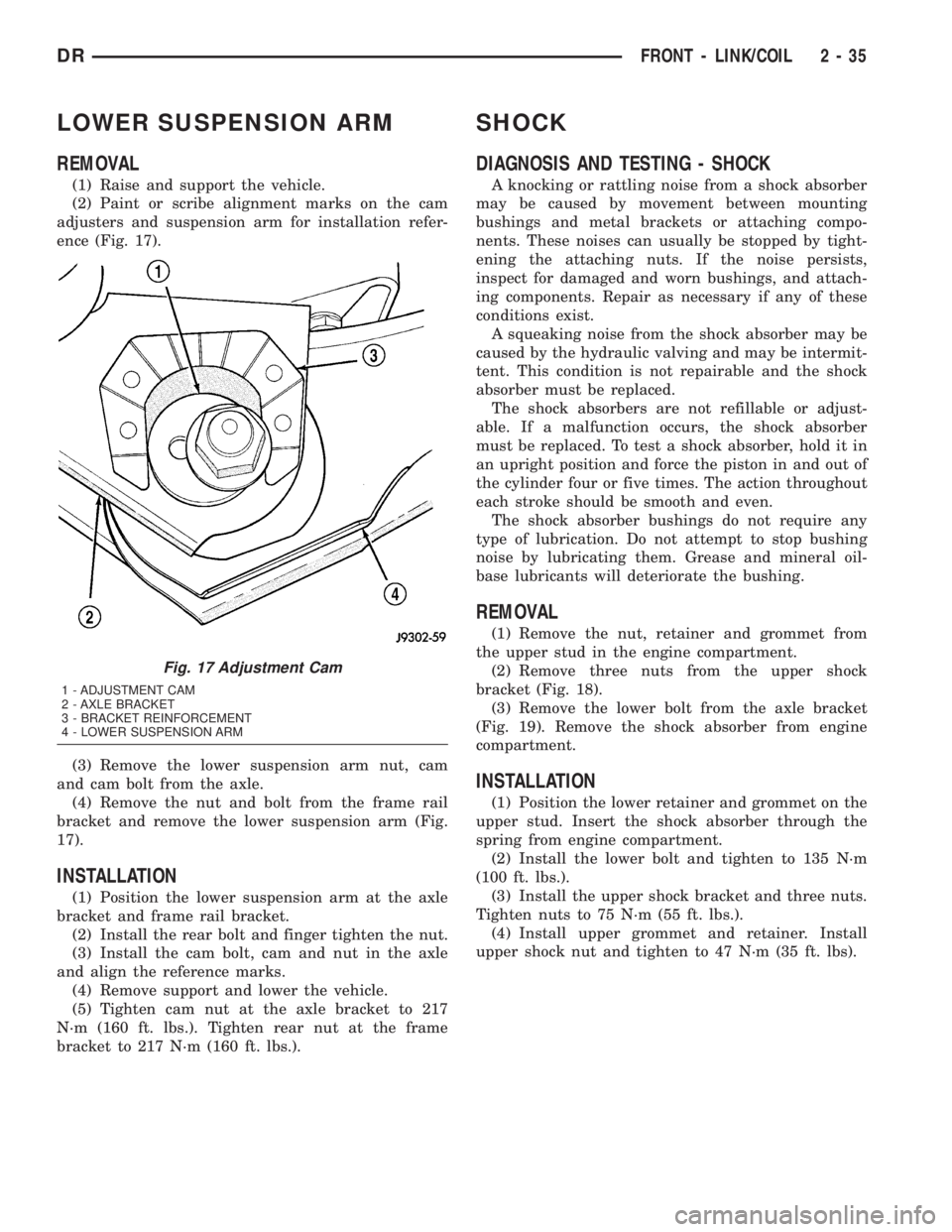
(2) Paint or scribe alignment marks on the cam
adjusters and suspension arm for installation refer-
ence (Fig. 17).
(3) Remove the lower suspension arm nut, cam
and cam bolt from the axle.
(4) Remove the nut and bolt from the frame rail
bracket and remove the lower suspension arm (Fig.
17).
INSTALLATION
(1) Position the lower suspension arm at the axle
bracket and frame rail bracket.
(2) Install the rear bolt and finger tighten the nut.
(3) Install the cam bolt, cam and nut in the axle
and align the reference marks.
(4) Remove support and lower the vehicle.
(5) Tighten cam nut at the axle bracket to 217
N´m (160 ft. lbs.). Tighten rear nut at the frame
bracket to 217 N´m (160 ft. lbs.).
SHOCK
DIAGNOSIS AND TESTING - SHOCK
A knocking or rattling noise from a shock absorber
may be caused by movement between mounting
bushings and metal brackets or attaching compo-
nents. These noises can usually be stopped by tight-
ening the attaching nuts. If the noise persists,
inspect for damaged and worn bushings, and attach-
ing components. Repair as necessary if any of these
conditions exist.
A squeaking noise from the shock absorber may be
caused by the hydraulic valving and may be intermit-
tent. This condition is not repairable and the shock
absorber must be replaced.
The shock absorbers are not refillable or adjust-
able. If a malfunction occurs, the shock absorber
must be replaced. To test a shock absorber, hold it in
an upright position and force the piston in and out of
the cylinder four or five times. The action throughout
each stroke should be smooth and even.
The shock absorber bushings do not require any
type of lubrication. Do not attempt to stop bushing
noise by lubricating them. Grease and mineral oil-
base lubricants will deteriorate the bushing.
REMOVAL
(1) Remove the nut, retainer and grommet from
the upper stud in the engine compartment.
(2) Remove three nuts from the upper shock
bracket (Fig. 18).
(3) Remove the lower bolt from the axle bracket
(Fig. 19). Remove the shock absorber from engine
compartment.
INSTALLATION
(1) Position the lower retainer and grommet on the
upper stud. Insert the shock absorber through the
spring from engine compartment.
(2) Install the lower bolt and tighten to 135 N´m
(100 ft. lbs.).
(3) Install the upper shock bracket and three nuts.
Tighten nuts to 75 N´m (55 ft. lbs.).
(4) Install upper grommet and retainer. Install
upper shock nut and tighten to 47 N´m (35 ft. lbs).
Fig. 17 Adjustment Cam
1 - ADJUSTMENT CAM
2 - AXLE BRACKET
3 - BRACKET REINFORCEMENT
4 - LOWER SUSPENSION ARM
DRFRONT - LINK/COIL 2 - 35
Page 67 of 2895
REAR
TABLE OF CONTENTS
page page
REAR
DESCRIPTION.........................38
DIAGNOSIS AND TESTING - SPRING AND
SHOCK.............................38
SPECIFICATIONS
TORQUE CHART......................39
BUSHINGS
REMOVAL.............................39
INSTALLATION.........................39
JOUNCE BUMPER
REMOVAL.............................40
INSTALLATION.........................40
AUXILIARY SPRING BUMPERS (3500)
REMOVAL.............................40INSTALLATION.........................40
SHOCK
REMOVAL.............................40
INSTALLATION.........................40
SPRING
DESCRIPTION.........................41
OPERATION...........................41
REMOVAL.............................41
INSTALLATION.........................41
SPRING TIP INSERTS
REMOVAL.............................41
INSTALLATION.........................42
REAR
DESCRIPTION
The rear suspension is comprised of:
²Shock Absorbers
²Jounce Bumpers
²Stabilizer Bar (optional)
²Leaf Springs
²Auxiliary Leaf Spring (3500 series)
²Auxiliary Spring Bumpers (3500 series)
²Drive Axle
CAUTION: A vehicle should always be loaded so
the vehicle weight center-line is located immedi-
ately forward of the rear axle. Correct vehicle load-
ing provides proper front tire-to-road contact. This
results in maximum vehicle handling stability and
safety. Incorrect vehicle weight distribution can
cause excessive tire tread wear, spring fatigue or
failure, and erratic steering.
CAUTION: Suspension components with rubber/ure-
thane bushings (except stabilizer bar) should be
tightened with the vehicle at normal ride height. It is
important to have the springs supporting the weight
of the vehicle when the fasteners are torqued. If
springs are not at their normal ride position, vehicle
ride comfort could be affected and premature bush-
ing wear may occur.
DIAGNOSIS AND TESTING - SPRING AND
SHOCK
A knocking or rattling noise from a shock absorber
may be caused by movement between mounting
bushings and metal brackets or attaching compo-
nents. These noises can usually be stopped by tight-
ening the attaching nuts. If the noise persists,
inspect for damaged and worn bushings, and attach-
ing components. Repair as necessary if any of these
conditions exist.
A squeaking noise from the shock absorber may be
caused by the hydraulic valving and may be intermit-
tent. This condition is not repairable and the shock
absorber must be replaced.
The shock absorbers are not refillable or adjust-
able. If a malfunction occurs, the shock absorber
must be replaced. To test a shock absorber, hold it in
an upright position and force the piston in and out of
the cylinder four or five times. The action throughout
each stroke should be smooth and even.
The spring eye and shock absorber bushings do not
require any type of lubrication. Do not attempt to
stop spring bushing noise by lubricating them.
Grease and mineral oil-base lubricants will deterio-
rate the bushing rubber.
If the vehicle is used for severe, off-road operation,
the springs should be examined periodically. Check
for broken and shifted leafs, loose and missing clips,
and broken center bolts. Refer to Spring and Shock
Absorber Diagnosis chart for additional information.
2 - 38 REARDR
Page 68 of 2895
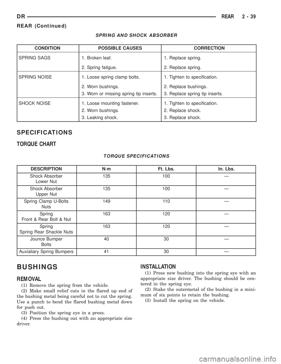
SPRING AND SHOCK ABSORBER
CONDITION POSSIBLE CAUSES CORRECTION
SPRING SAGS 1. Broken leaf. 1. Replace spring.
2. Spring fatigue. 2. Replace spring.
SPRING NOISE 1. Loose spring clamp bolts. 1. Tighten to specification.
2. Worn bushings. 2. Replace bushings.
3. Worn or missing spring tip inserts. 3. Replace spring tip inserts.
SHOCK NOISE 1. Loose mounting fastener. 1. Tighten to specification.
2. Worn bushings. 2. Replace shock.
3. Leaking shock. 3. Replace shock.
SPECIFICATIONS
TORQUE CHART
TORQUE SPECIFICATIONS
DESCRIPTION N´m Ft. Lbs. In. Lbs.
Shock Absorber
Lower Nut135 100 Ð
Shock Absorber
Upper Nut135 100 Ð
Spring Clamp U-Bolts
Nuts149 110 Ð
Spring
Front & Rear Bolt & Nut163 120 Ð
Spring
Spring Rear Shackle Nuts163 120 Ð
Jounce Bumper
Bolts40 30 Ð
Auxialiary Spring Bumpers 41 30 Ð
BUSHINGS
REMOVAL
(1) Remove the spring from the vehicle.
(2) Make small relief cuts in the flared up end of
the bushing metal being careful not to cut the spring.
Use a punch to bend the flared bushing metal down
for push out.
(3) Position the spring eye in a press.
(4) Press the bushing out with an appropriate size
driver.
INSTALLATION
(1) Press new bushing into the spring eye with an
appropriate size driver. The bushing should be cen-
tered in the spring eye.
(2) Stake the outermetal of the bushing in a mini-
mum of six points to retain the bushing.
(3) Install the spring on the vehicle.
DRREAR 2 - 39
REAR (Continued)
Page 70 of 2895
SPRING
DESCRIPTION
The rear suspension system uses a multi-leaf
springs and a solid drive axle. The forward end of the
springs are mounted to the body rail hangers
through rubber bushings. The rearward end of the
springs are attached to the body by the use of shack-
les. The spring and shackles use rubber bushings.
OPERATION
The springs control ride quality and maintain vehi-
cle ride height. The shackles allow the springs to
change their length as the vehicle moves over various
road conditions.
REMOVAL
(1) Raise and support the vehicle.
(2) Support the axle with a suitable holding fix-
ture.
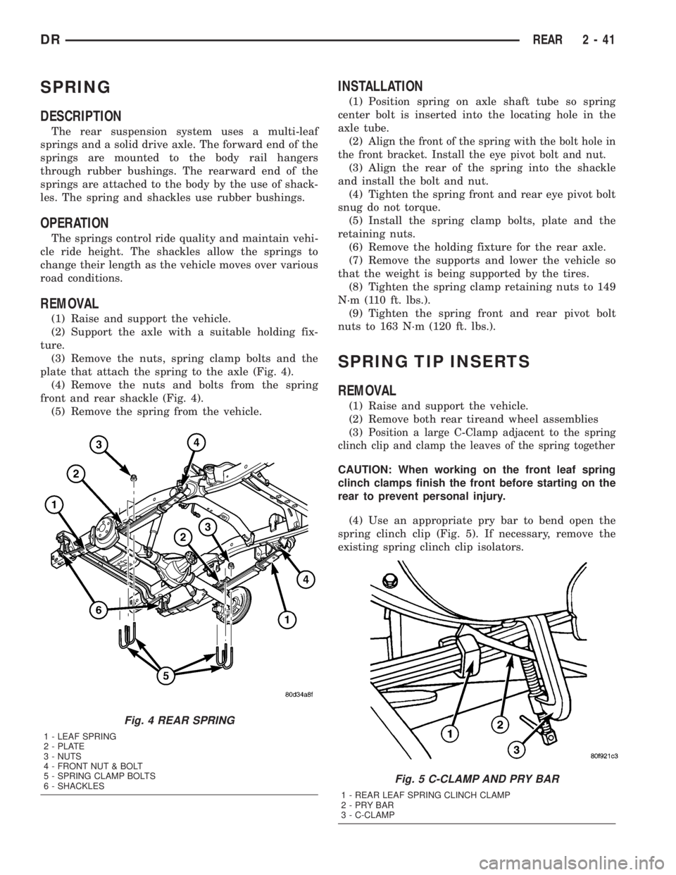
(3) Remove the nuts, spring clamp bolts and the
plate that attach the spring to the axle (Fig. 4).
(4) Remove the nuts and bolts from the spring
front and rear shackle (Fig. 4).
(5) Remove the spring from the vehicle.
INSTALLATION
(1) Position spring on axle shaft tube so spring
center bolt is inserted into the locating hole in the
axle tube.
(2)
Align the front of the spring with the bolt hole in
the front bracket. Install the eye pivot bolt and nut.
(3) Align the rear of the spring into the shackle
and install the bolt and nut.
(4) Tighten the spring front and rear eye pivot bolt
snug do not torque.
(5) Install the spring clamp bolts, plate and the
retaining nuts.
(6) Remove the holding fixture for the rear axle.
(7) Remove the supports and lower the vehicle so
that the weight is being supported by the tires.
(8) Tighten the spring clamp retaining nuts to 149
N´m (110 ft. lbs.).
(9) Tighten the spring front and rear pivot bolt
nuts to 163 N´m (120 ft. lbs.).
SPRING TIP INSERTS
REMOVAL
(1) Raise and support the vehicle.
(2) Remove both rear tireand wheel assemblies
(3)
Position a large C-Clamp adjacent to the spring
clinch clip and clamp the leaves of the spring together
CAUTION: When working on the front leaf spring
clinch clamps finish the front before starting on the
rear to prevent personal injury.
(4) Use an appropriate pry bar to bend open the
spring clinch clip (Fig. 5). If necessary, remove the
existing spring clinch clip isolators.
Fig. 4 REAR SPRING
1 - LEAF SPRING
2 - PLATE
3 - NUTS
4 - FRONT NUT & BOLT
5 - SPRING CLAMP BOLTS
6 - SHACKLES
Fig. 5 C-CLAMP AND PRY BAR
1 - REAR LEAF SPRING CLINCH CLAMP
2-PRYBAR
3 - C-CLAMP
DRREAR 2 - 41
Page 89 of 2895
CV JOINT-INNER
REMOVAL
(1) Clamp shaft in a vise (with soft jaws) and sup-
port C/V joint.
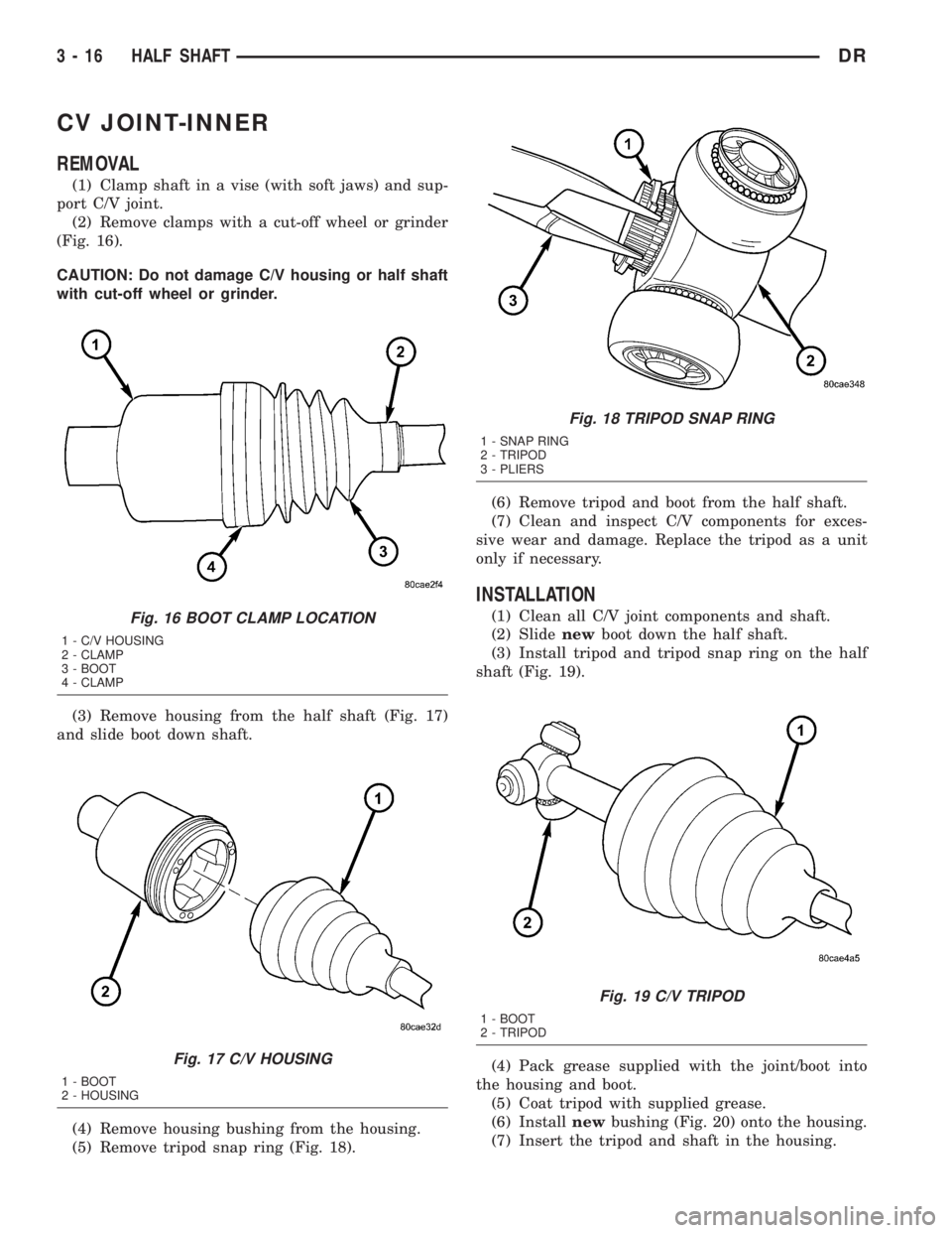
(2) Remove clamps with a cut-off wheel or grinder
(Fig. 16).
CAUTION: Do not damage C/V housing or half shaft
with cut-off wheel or grinder.
(3) Remove housing from the half shaft (Fig. 17)
and slide boot down shaft.
(4) Remove housing bushing from the housing.
(5) Remove tripod snap ring (Fig. 18).(6) Remove tripod and boot from the half shaft.
(7) Clean and inspect C/V components for exces-
sive wear and damage. Replace the tripod as a unit
only if necessary.
INSTALLATION
(1) Clean all C/V joint components and shaft.
(2) Slidenewboot down the half shaft.
(3) Install tripod and tripod snap ring on the half
shaft (Fig. 19).
(4) Pack grease supplied with the joint/boot into
the housing and boot.
(5) Coat tripod with supplied grease.
(6) Installnewbushing (Fig. 20) onto the housing.
(7) Insert the tripod and shaft in the housing.Fig. 16 BOOT CLAMP LOCATION
1 - C/V HOUSING
2 - CLAMP
3 - BOOT
4 - CLAMP
Fig. 17 C/V HOUSING
1 - BOOT
2 - HOUSING
Fig. 18 TRIPOD SNAP RING
1 - SNAP RING
2 - TRIPOD
3 - PLIERS
Fig. 19 C/V TRIPOD
1 - BOOT
2 - TRIPOD
3 - 16 HALF SHAFTDR
Page 90 of 2895
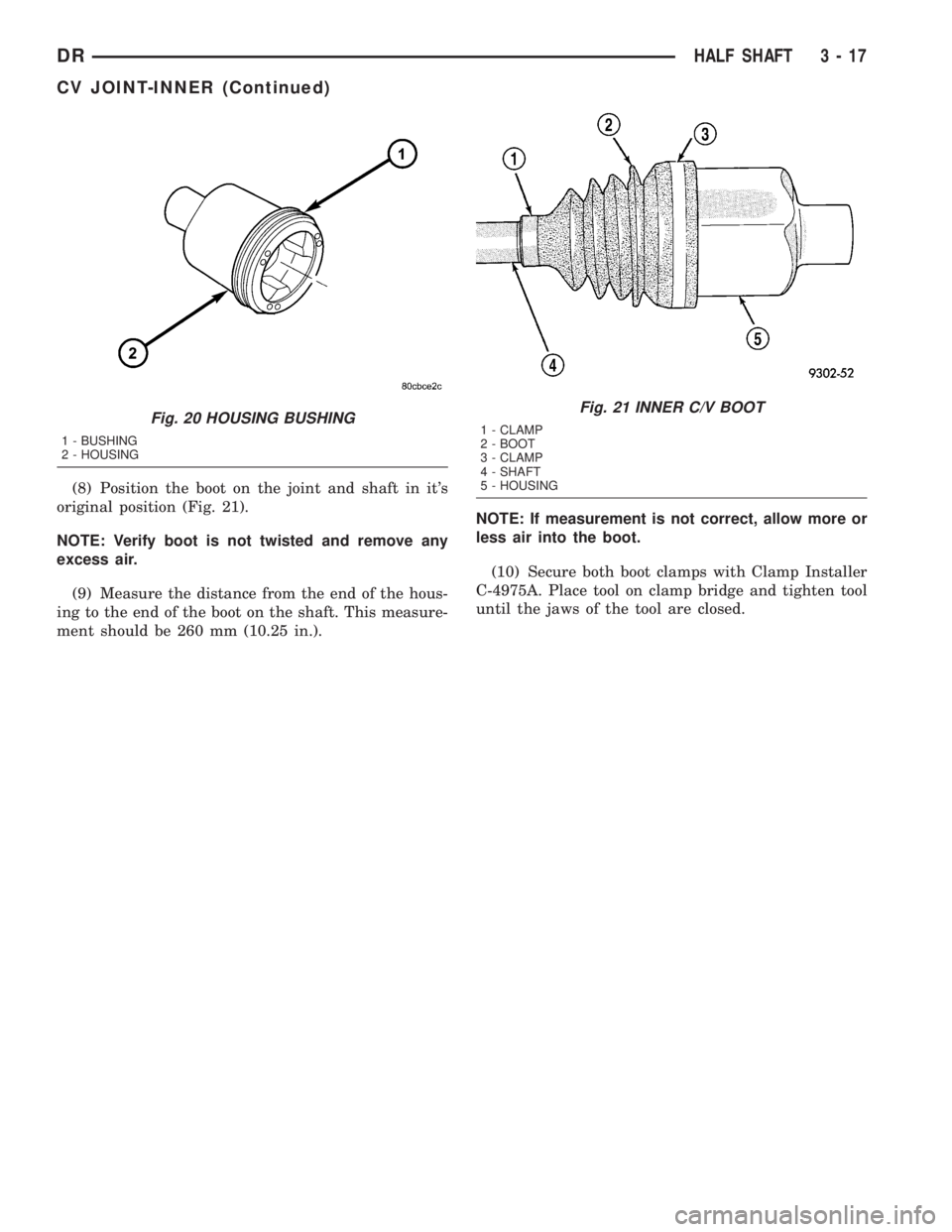
(8) Position the boot on the joint and shaft in it's
original position (Fig. 21).
NOTE: Verify boot is not twisted and remove any
excess air.
(9) Measure the distance from the end of the hous-
ing to the end of the boot on the shaft. This measure-
ment should be 260 mm (10.25 in.).NOTE: If measurement is not correct, allow more or
less air into the boot.
(10) Secure both boot clamps with Clamp Installer
C-4975A. Place tool on clamp bridge and tighten tool
until the jaws of the tool are closed.
Fig. 20 HOUSING BUSHING
1 - BUSHING
2 - HOUSING
Fig. 21 INNER C/V BOOT
1 - CLAMP
2 - BOOT
3 - CLAMP
4 - SHAFT
5 - HOUSING
DRHALF SHAFT 3 - 17
CV JOINT-INNER (Continued)
Page 121 of 2895
Condition Possible Causes Correction
Gear Teeth Broke 1. Overloading. 1. Replace gears. Examine other
gears and bearings for possible
damage.
2. Erratic clutch operation. 2. Replace gears and examine the
remaining parts for damage. Avoid
erratic clutch operation.
3. Ice-spotted pavement. 3. Replace gears and examine
remaining parts for damage.
4. Improper adjustments. 4. Replace gears and examine
remaining parts for damage. Ensure
ring gear backlash is correct.
Axle Noise 1. Insufficient lubricant. 1. Fill differential with the correct
fluid type and quantity.
2. Improper ring gear and pinion
adjustment.2. Check ring gear and pinion
contact pattern.
3. Unmatched ring gear and pinion. 3. Replace gears with a matched
ring gear and pinion.
4. Worn teeth on ring gear and/or
pinion.4. Replace ring gear and pinion.
5. Loose pinion bearings. 5. Adjust pinion bearing pre-load.
6. Loose differential bearings. 6. Adjust differential bearing
pre-load.
7. Mis-aligned or sprung ring gear. 7. Measure ring gear run-out.
Replace components as necessary.
8. Loose differential bearing cap
bolts.8. Inspect differential components
and replace as necessary. Ensure
that the bearing caps are torqued
tot he proper specification.
9. Housing not machined properly. 9. Replace housing.
REMOVAL
(1) Remove wheels and tires.
(2) Remove brake calipers and rotors.
(3) Disconnect ABS wheel speed sensors.
(4) Disconnect axle vent hose.
(5) Remove front propeller shaft.
(6) Disconnect stabilizer bar links at the axle
brackets.
(7) Disconnect shock absorbers from axle brackets.
(8) Disconnect track bar from the axle bracket.
(9) Disconnect tie rod and drag link from the steer-
ing knuckles.
(10) Position suitable lifting device under the axle
assembly.
(11) Secure axle to lifting device.
(12) Mark suspension alignment cams for installa-
tion reference.
(13) Disconnect upper and lower suspension arms
from the axle bracket.(14) Lower the axle. The coil springs will drop
with the axle.
(15) Remove the coil springs from the axle bracket.
INSTALLATION
CAUTION: Suspension components with rubber
bushings should be tightened with the weight of the
vehicle on the suspension, at normal height. If
springs are not at their normal ride position, vehicle
ride comfort could be affected and premature bush-
ing wear may occur. Rubber bushings must never
be lubricated.
(1) Support the axle on a suitable lifting device.
(2) Secure axle to lifting device.
(3) Position the axle under the vehicle.
(4) Install springs, retainer clip and bolts.
(5) Raise axle and align it with the spring pads.
3 - 48 FRONT AXLE - 9 1/4 AADR
FRONT AXLE - 9 1/4 AA (Continued)
Page 230 of 2895
and cups will also have to be replaced after flush-
ing. Use clean brake fluid to flush the system.
(4) Check parking brake operation. Verify free
movement and full release of cables and pedal. Also
note if vehicle was being operated with parking
brake partially applied.
(5) Check brake pedal operation. Verify that pedal
does not bind and has adequate free play. If pedal
lacks free play, check pedal and power booster for
being loose or for bind condition. Do not road test
until condition is corrected.
(6) Check booster vacuum check valve and hose.
(7) If components checked appear OK, road test
the vehicle.
ROAD TESTING
(1) If complaint involved low brake pedal, pump
pedal and note if it comes back up to normal height.
(2) Check brake pedal response with transmission
in Neutral and engine running. Pedal should remain
firm under constant foot pressure.
(3) During road test, make normal and firm brake
stops in 25-40 mph range. Note faulty brake opera-
tion such as low pedal, hard pedal, fade, pedal pulsa-
tion, pull, grab, drag, noise, etc.
(4) Attempt to stop the vehicle with the parking
brake only and note grab, drag, noise, etc.
PEDAL FALLS AWAY
A brake pedal that falls away under steady foot
pressure is generally the result of a system leak. The
leak point could be at a brake line, fitting, hose, or
caliper/wheel cylinder. If leakage is severe, fluid will
be evident at or around the leaking component.
Internal leakage (seal by-pass) in the master cylin-
der caused by worn or damaged piston cups, may
also be the problem cause.
An internal leak in the ABS or RWAL system may
also be the problem with no physical evidence.
LOW PEDAL
If a low pedal is experienced, pump the pedal sev-
eral times. If the pedal comes back up worn linings,
rotors, drums, or rear brakes out of adjustment are
the most likely causes. The proper course of action is
to inspect and replace all worn component and make
the proper adjustments.
SPONGY PEDAL
A spongy pedal is most often caused by air in the
system. However, thin brake drums or substandard
brake lines and hoses can also cause a spongy pedal.
The proper course of action is to bleed the system,
and replace thin drums and substandard quality
brake hoses if suspected.HARD PEDAL OR HIGH PEDAL EFFORT
A hard pedal or high pedal effort may be due to
lining that is water soaked, contaminated, glazed, or
badly worn. The power booster or check valve could
also be faulty.
PEDAL PULSATION
Pedal pulsation is caused by components that are
loose, or beyond tolerance limits.
The primary cause of pulsation are disc brake
rotors with excessive lateral runout or thickness vari-
ation, or out of round brake drums. Other causes are
loose wheel bearings or calipers and worn, damaged
tires.
NOTE: Some pedal pulsation may be felt during
ABS activation.
BRAKE DRAG
Brake drag occurs when the lining is in constant
contact with the rotor or drum. Drag can occur at one
wheel, all wheels, fronts only, or rears only.
Drag is a product of incomplete brake shoe release.
Drag can be minor or severe enough to overheat the
linings, rotors and drums.
Minor drag will usually cause slight surface char-
ring of the lining. It can also generate hard spots in
rotors and drums from the overheat-cool down pro-
cess. In most cases, the rotors, drums, wheels and
tires are quite warm to the touch after the vehicle is
stopped.
Severe drag can char the brake lining all the way
through. It can also distort and score rotors and
drums to the point of replacement. The wheels, tires
and brake components will be extremely hot. In
severe cases, the lining may generate smoke as it
chars from overheating.
Common causes of brake drag are:
²Seized or improperly adjusted parking brake
cables.
²Loose/worn wheel bearing.
²Seized caliper or wheel cylinder piston.
²Caliper binding on corroded bushings or rusted
slide surfaces.
²Loose caliper mounting.
²Drum brake shoes binding on worn/damaged
support plates.
²Mis-assembled components.
²Long booster output rod.
If brake drag occurs at all wheels, the problem
may be related to a blocked master cylinder return
port, or faulty power booster (binds-does not release).
BRAKE FADE
Brake fade is usually a product of overheating
caused by brake drag. However, brake overheating
DRBRAKES - BASE 5 - 3
BRAKES - BASE (Continued)
Page 241 of 2895
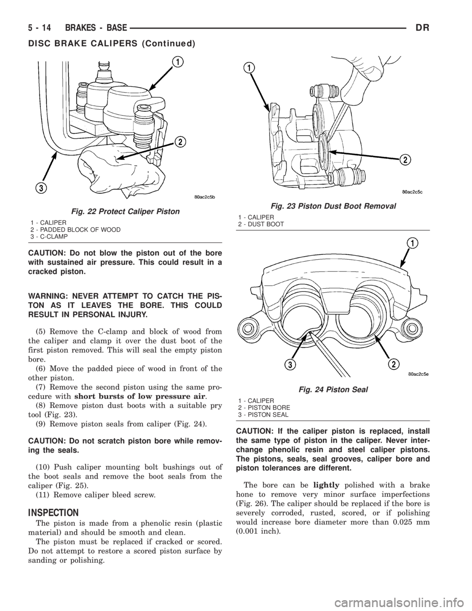
CAUTION: Do not blow the piston out of the bore
with sustained air pressure. This could result in a
cracked piston.
WARNING: NEVER ATTEMPT TO CATCH THE PIS-
TON AS IT LEAVES THE BORE. THIS COULD
RESULT IN PERSONAL INJURY.
(5) Remove the C-clamp and block of wood from
the caliper and clamp it over the dust boot of the
first piston removed. This will seal the empty piston
bore.
(6) Move the padded piece of wood in front of the
other piston.
(7) Remove the second piston using the same pro-
cedure withshort bursts of low pressure air.
(8) Remove piston dust boots with a suitable pry
tool (Fig. 23).
(9) Remove piston seals from caliper (Fig. 24).
CAUTION: Do not scratch piston bore while remov-
ing the seals.
(10) Push caliper mounting bolt bushings out of
the boot seals and remove the boot seals from the
caliper (Fig. 25).
(11) Remove caliper bleed screw.
INSPECTION
The piston is made from a phenolic resin (plastic
material) and should be smooth and clean.
The piston must be replaced if cracked or scored.
Do not attempt to restore a scored piston surface by
sanding or polishing.CAUTION: If the caliper piston is replaced, install
the same type of piston in the caliper. Never inter-
change phenolic resin and steel caliper pistons.
The pistons, seals, seal grooves, caliper bore and
piston tolerances are different.
The bore can belightlypolished with a brake
hone to remove very minor surface imperfections
(Fig. 26). The caliper should be replaced if the bore is
severely corroded, rusted, scored, or if polishing
would increase bore diameter more than 0.025 mm
(0.001 inch).
Fig. 22 Protect Caliper Piston
1 - CALIPER
2 - PADDED BLOCK OF WOOD
3 - C-CLAMP
Fig. 23 Piston Dust Boot Removal
1 - CALIPER
2 - DUST BOOT
Fig. 24 Piston Seal
1 - CALIPER
2 - PISTON BORE
3 - PISTON SEAL
5 - 14 BRAKES - BASEDR
DISC BRAKE CALIPERS (Continued)