bushing DODGE RAM 2003 Service Repair Manual
[x] Cancel search | Manufacturer: DODGE, Model Year: 2003, Model line: RAM, Model: DODGE RAM 2003Pages: 2895, PDF Size: 83.15 MB
Page 30 of 2895
SUSPENSION
TABLE OF CONTENTS
page page
WHEEL ALIGNMENT......................1
FRONT - INDEPENDENT FRONT SUSPENSION..8FRONT - LINK/COIL......................28
REAR.................................38
WHEEL ALIGNMENT
TABLE OF CONTENTS
page page
WHEEL ALIGNMENT
DESCRIPTION..........................1
OPERATION............................2
DIAGNOSIS AND TESTING - PRE-ALIGNMENT
INSPECTION..........................2
STANDARD PROCEDURE
STANDARD PROCEDURE - HEIGHT
MEASUREMENT - 4WD (LD)..............3
STANDARD PROCEDURE - HEIGHT
ADJUSTMENT - 4WD (LD)................3
STANDARD PROCEDURE - CAMBER AND
CASTER ADJUSTMENT..................4STANDARD PROCEDURE - TOE
ADJUSTMENT.........................4
STANDARD PROCEDURE - CAMBER,
CASTER AND TOE ADJUSTMENT..........4
STANDARD PROCEDURE - ALIGNMENT
LINK/COIL SUSPENSION.................5
SPECIFICATIONS
ALIGNMENT..........................6
SPECIAL TOOLS
WHEEL ALIGNMENT....................7
WHEEL ALIGNMENT
DESCRIPTION
NOTE: Suspension components with rubber/ure-
thane bushings should be tightened with the vehi-
cle at normal ride height. It is important to have the
springs supporting the weight of the vehicle when
the fasteners are torqued. If springs are not at their
normal ride position, vehicle ride comfort could be
affected and premature bushing wear may occur.
Wheel alignment involves the correct positioning of
the wheels in relation to the vehicle. The positioning
is accomplished through suspension and steering
linkage adjustments. An alignment is considered
essential for efficient steering, good directional stabil-
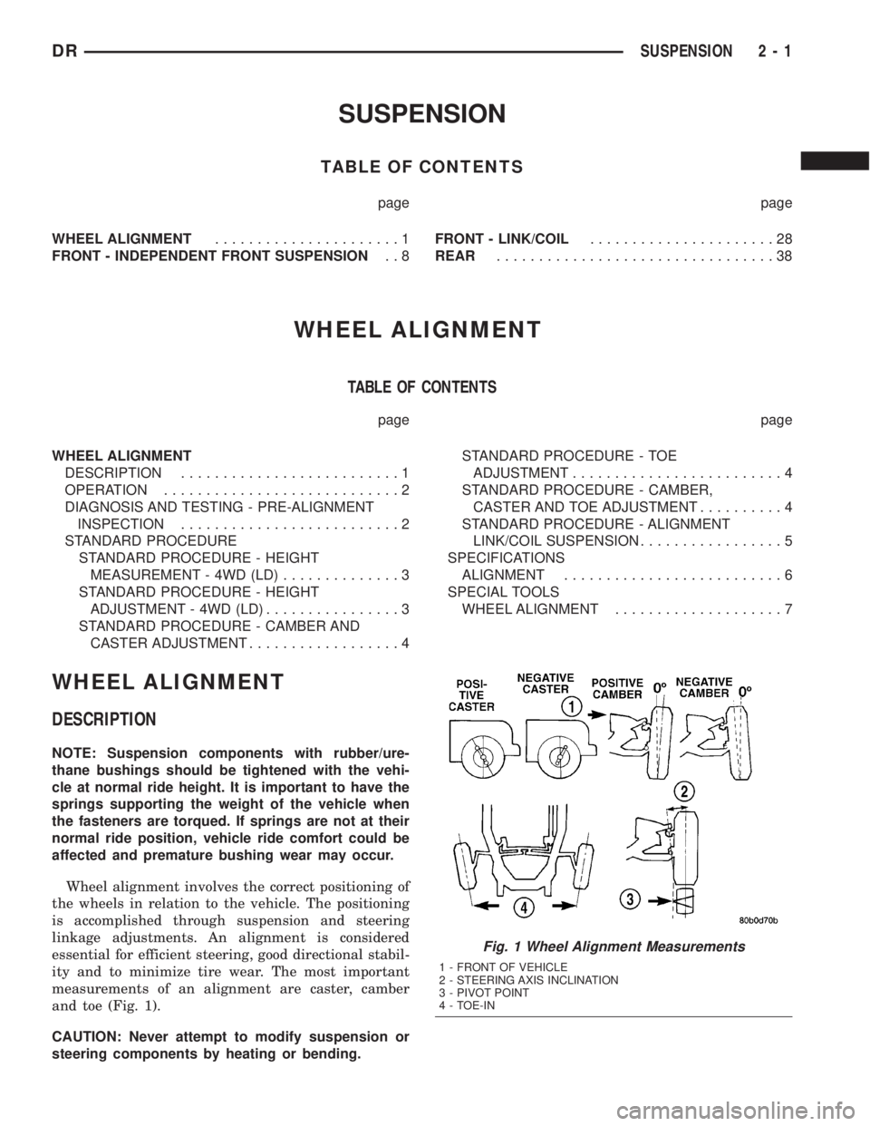
ity and to minimize tire wear. The most important
measurements of an alignment are caster, camber
and toe (Fig. 1).
CAUTION: Never attempt to modify suspension or
steering components by heating or bending.
Fig. 1 Wheel Alignment Measurements
1 - FRONT OF VEHICLE
2 - STEERING AXIS INCLINATION
3 - PIVOT POINT
4 - TOE-IN
DRSUSPENSION 2 - 1
Page 37 of 2895
FRONT - INDEPENDENT FRONT SUSPENSION
TABLE OF CONTENTS
page page
FRONT - INDEPENDENT FRONT SUSPENSION
DESCRIPTION
DESCRIPTION........................9
DESCRIPTION........................9
SPECIFICATIONS
TORQUE CHART......................10
SPECIAL TOOLS
FRONT SUSPENSION..................11
BUSHINGS
REMOVAL
REMOVAL - LOWER CONTROL ARM
BUSHINGS - 4WD (LD).................12
REMOVAL - TORSION BAR
CROSSMEMBER BUSHING..............12
REMOVAL - LOWER CONTROL ARM
BUSHINGS - 2WD (LD).................12
INSTALLATION
INSTALLATION - LOWER CONTROL ARM
BUSHINGS - 4WD (LD).................13
INSTALLATION - TORSION BAR CROSS
MEMBER BUSHING....................14
INSTALLATION - LOWER CONTROL ARM
BUSHINGS - 2WD (LD).................14
HUB / BEARING
REMOVAL
REMOVAL - 4X4......................15
REMOVAL - 4X2......................16
INSTALLATION
INSTALLATION - 4X4...................16
INSTALLATION - 4X2...................17
KNUCKLE
DESCRIPTION.........................17
OPERATION...........................17
REMOVAL.............................17
INSTALLATION.........................18
LOWER BALL JOINT
DIAGNOSIS AND TESTING - LOWER BALL
JOINT..............................18
REMOVAL.............................18
INSTALLATION.........................19LOWER CONTROL ARM
REMOVAL
REMOVAL - 4X4 (LD)...................20
REMOVAL - 4X2......................20
INSTALLATION
INSTALLATION - 4X4 (LD)...............21
INSTALLATION - 4X2...................21
SPRING
REMOVAL.............................21
INSTALLATION.........................22
SHOCK
DIAGNOSIS AND TESTING - SHOCK........23
REMOVAL
REMOVAL - 4X2......................23
REMOVAL - 4X4......................23
INSTALLATION
INSTALLATION - 4X2...................23
INSTALLATION - 4X4...................23
STABILIZER BAR
DESCRIPTION.........................24
OPERATION...........................24
REMOVAL.............................24
INSTALLATION.........................24
STABILIZER LINK
REMOVAL
REMOVAL - 4X4......................24
REMOVAL - 4X2......................24
INSTALLATION
INSTALLATION - 4X4...................25
INSTALLATION - 4X2...................25
TORSION BAR
DESCRIPTION.........................25
OPERATION...........................25
REMOVAL.............................25
INSTALLATION.........................26
UPPER BALL JOINT
DIAGNOSIS AND TESTING - UPPER BALL
JOINT..............................26
UPPER CONTROL ARM
REMOVAL.............................27
INSTALLATION.........................27
2 - 8 FRONT - INDEPENDENT FRONT SUSPENSIONDR
Page 38 of 2895
FRONT - INDEPENDENT
FRONT SUSPENSION
DESCRIPTION
DESCRIPTION
The front suspension is designed to allow each
wheel to adapt to different road surfaces indepen-
dently. The wheels are mounted to hub/bearings
units bolted to the steering knuckle. The double-row
hub bearings are sealed and lubricated for life. The
steering knuckles turn (pivot) on ball joints.
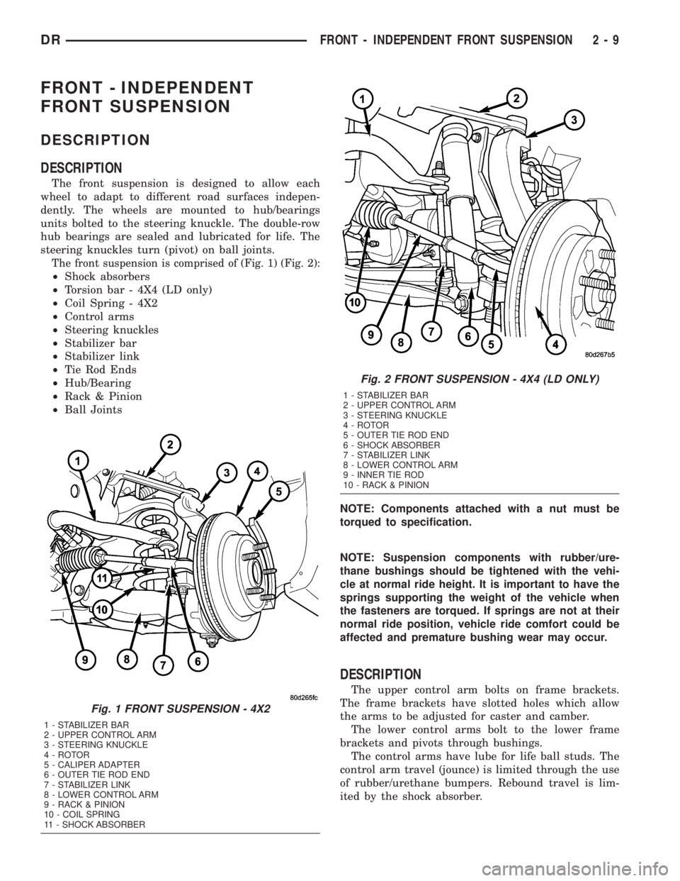
The front suspension is comprised of (Fig. 1) (Fig. 2):
²Shock absorbers
²Torsion bar - 4X4 (LD only)
²Coil Spring - 4X2
²Control arms
²Steering knuckles
²Stabilizer bar
²Stabilizer link
²Tie Rod Ends
²Hub/Bearing
²Rack & Pinion
²Ball Joints
NOTE: Components attached with a nut must be
torqued to specification.
NOTE: Suspension components with rubber/ure-
thane bushings should be tightened with the vehi-
cle at normal ride height. It is important to have the
springs supporting the weight of the vehicle when
the fasteners are torqued. If springs are not at their
normal ride position, vehicle ride comfort could be
affected and premature bushing wear may occur.
DESCRIPTION
The upper control arm bolts on frame brackets.
The frame brackets have slotted holes which allow
the arms to be adjusted for caster and camber.
The lower control arms bolt to the lower frame
brackets and pivots through bushings.
The control arms have lube for life ball studs. The
control arm travel (jounce) is limited through the use
of rubber/urethane bumpers. Rebound travel is lim-
ited by the shock absorber.
Fig. 1 FRONT SUSPENSION - 4X2
1 - STABILIZER BAR
2 - UPPER CONTROL ARM
3 - STEERING KNUCKLE
4 - ROTOR
5 - CALIPER ADAPTER
6 - OUTER TIE ROD END
7 - STABILIZER LINK
8 - LOWER CONTROL ARM
9 - RACK & PINION
10 - COIL SPRING
11 - SHOCK ABSORBER
Fig. 2 FRONT SUSPENSION - 4X4 (LD ONLY)
1 - STABILIZER BAR
2 - UPPER CONTROL ARM
3 - STEERING KNUCKLE
4 - ROTOR
5 - OUTER TIE ROD END
6 - SHOCK ABSORBER
7 - STABILIZER LINK
8 - LOWER CONTROL ARM
9 - INNER TIE ROD
10 - RACK & PINION
DRFRONT - INDEPENDENT FRONT SUSPENSION 2 - 9
Page 40 of 2895
SPECIAL TOOLS
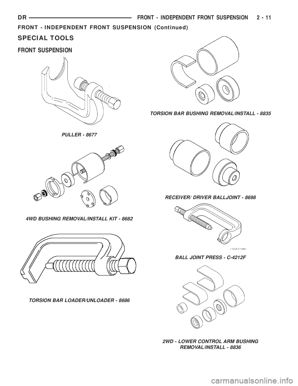
FRONT SUSPENSION
PULLER - 8677
4WD BUSHING REMOVAL/INSTALL KIT - 8682
TORSION BAR LOADER/UNLOADER - 8686
TORSION BAR BUSHING REMOVAL/INSTALL - 8835
RECEIVER/ DRIVER BALLJOINT - 8698
BALL JOINT PRESS - C-4212F
2WD - LOWER CONTROL ARM BUSHING
REMOVAL/INSTALL - 8836
DRFRONT - INDEPENDENT FRONT SUSPENSION 2 - 11
FRONT - INDEPENDENT FRONT SUSPENSION (Continued)
Page 41 of 2895
BUSHINGS
REMOVAL
REMOVAL - LOWER CONTROL ARM
BUSHINGS - 4WD (LD)
(1) Remove the lower control arm (Refer to 2 -
SUSPENSION/FRONT/LOWER CONTROL ARM -
REMOVAL).
(2) Secure the control arm in a vise.
NOTE: Extreme pressure lubrication must be used
on the threaded portions of the tool. This will
increase the longevity of the tool and insure proper
operation during the removal and installation pro-
cess.
FRAME MOUNTED BUSHING
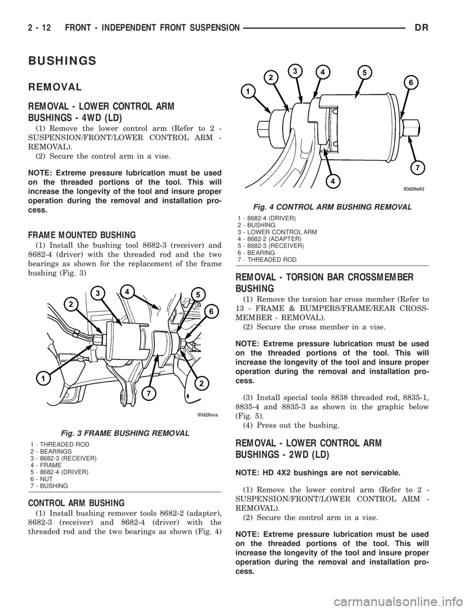
(1) Install the bushing tool 8682-3 (receiver) and
8682-4 (driver) with the threaded rod and the two
bearings as shown for the replacement of the frame
bushing (Fig. 3)
CONTROL ARM BUSHING
(1) Install bushing remover tools 8682-2 (adapter),
8682-3 (receiver) and 8682-4 (driver) with the
threaded rod and the two bearings as shown (Fig. 4)
REMOVAL - TORSION BAR CROSSMEMBER
BUSHING
(1) Remove the torsion bar cross member (Refer to
13 - FRAME & BUMPERS/FRAME/REAR CROSS-
MEMBER - REMOVAL).
(2) Secure the cross member in a vise.
NOTE: Extreme pressure lubrication must be used
on the threaded portions of the tool. This will
increase the longevity of the tool and insure proper
operation during the removal and installation pro-
cess.
(3) Install special tools 8838 threaded rod, 8835-1,
8835-4 and 8835-3 as shown in the graphic below
(Fig. 5).
(4) Press out the bushing.
REMOVAL - LOWER CONTROL ARM
BUSHINGS - 2WD (LD)
NOTE: HD 4X2 bushings are not servicable.
(1) Remove the lower control arm (Refer to 2 -
SUSPENSION/FRONT/LOWER CONTROL ARM -
REMOVAL).
(2) Secure the control arm in a vise.
NOTE: Extreme pressure lubrication must be used
on the threaded portions of the tool. This will
increase the longevity of the tool and insure proper
operation during the removal and installation pro-
cess.
Fig. 3 FRAME BUSHING REMOVAL
1 - THREADED ROD
2 - BEARINGS
3 - 8682-3 (RECEIVER)
4 - FRAME
5 - 8682-4 (DRIVER)
6 - NUT
7 - BUSHING
Fig. 4 CONTROL ARM BUSHING REMOVAL
1 - 8682-4 (DRIVER)
2 - BUSHING
3 - LOWER CONTROL ARM
4 - 8682-2 (ADAPTER)
5 - 8682-3 (RECEIVER)
6 - BEARING
7 - THREADED ROD
2 - 12 FRONT - INDEPENDENT FRONT SUSPENSIONDR
Page 42 of 2895
LARGE BUSHING
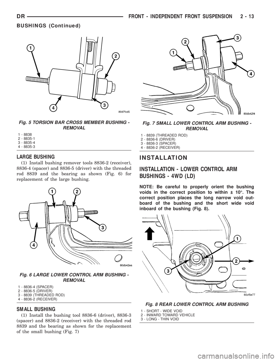
(1) Install bushing remover tools 8836-2 (receiver),
8836-4 (spacer) and 8836-5 (driver) with the threaded
rod 8839 and the bearing as shown (Fig. 6) for
replacement of the large bushing.
SMALL BUSHING
(1) Install the bushing tool 8836-6 (driver), 8836-3
(spacer) and 8836-2 (receiver) with the threaded rod
8839 and the bearing as shown for the replacement
of the small bushing (Fig. 7)
INSTALLATION
INSTALLATION - LOWER CONTROL ARM
BUSHINGS - 4WD (LD)
NOTE: Be careful to properly orient the bushing
voids in the correct position to within 10É. The
correct position places the long narrow void out-
board of the bushing and the short wide void
inboard of the bushing (Fig. 8).
Fig. 5 TORSION BAR CROSS MEMBER BUSHING -
REMOVAL
1 - 8838
2 - 8835-1
3 - 8835-4
4 - 8835-3
Fig. 6 LARGE LOWER CONTROL ARM BUSHING -
REMOVAL
1 - 8836-4 (SPACER)
2 - 8836-5 (DRIVER)
3 - 8839 (THREADED ROD)
4 - 8836-2 (RECEIVER)
Fig. 7 SMALL LOWER CONTROL ARM BUSHING -
REMOVAL
1 - 8839 (THREADED ROD)
2 - 8836-6 (DRIVER)
3 - 8836-3 (SPACER)
4 - 8836-2 (RECEIVER)
Fig. 8 REAR LOWER CONTROL ARM BUSHING
1 - SHORT - WIDE VOID
2 - INWARD TOWARD VEHICLE
3 - LONG - THIN VOID
DRFRONT - INDEPENDENT FRONT SUSPENSION 2 - 13
BUSHINGS (Continued)
Page 43 of 2895
FRAME MOUNTED BUSHING
NOTE: Extreme pressure lubrication must be used
on the threaded portions of the tool. This will
increase the longevity of the tool and insure proper
operation during the removal and installation pro-
cess.
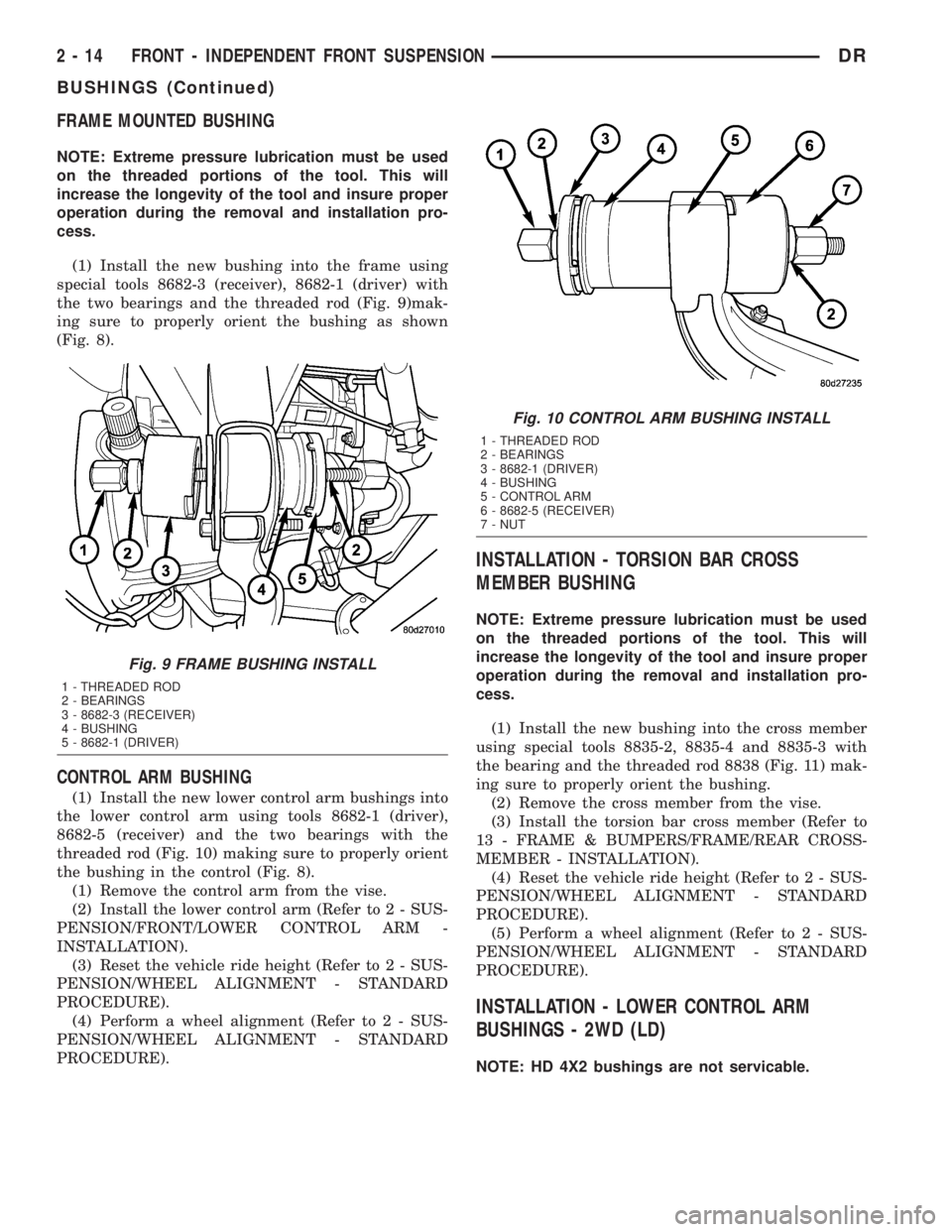
(1) Install the new bushing into the frame using
special tools 8682-3 (receiver), 8682-1 (driver) with
the two bearings and the threaded rod (Fig. 9)mak-
ing sure to properly orient the bushing as shown
(Fig. 8).
CONTROL ARM BUSHING
(1) Install the new lower control arm bushings into
the lower control arm using tools 8682-1 (driver),
8682-5 (receiver) and the two bearings with the
threaded rod (Fig. 10) making sure to properly orient
the bushing in the control (Fig. 8).
(1) Remove the control arm from the vise.
(2) Install the lower control arm (Refer to 2 - SUS-
PENSION/FRONT/LOWER CONTROL ARM -
INSTALLATION).
(3) Reset the vehicle ride height (Refer to 2 - SUS-
PENSION/WHEEL ALIGNMENT - STANDARD
PROCEDURE).
(4) Perform a wheel alignment (Refer to 2 - SUS-
PENSION/WHEEL ALIGNMENT - STANDARD
PROCEDURE).
INSTALLATION - TORSION BAR CROSS
MEMBER BUSHING
NOTE: Extreme pressure lubrication must be used
on the threaded portions of the tool. This will
increase the longevity of the tool and insure proper
operation during the removal and installation pro-
cess.
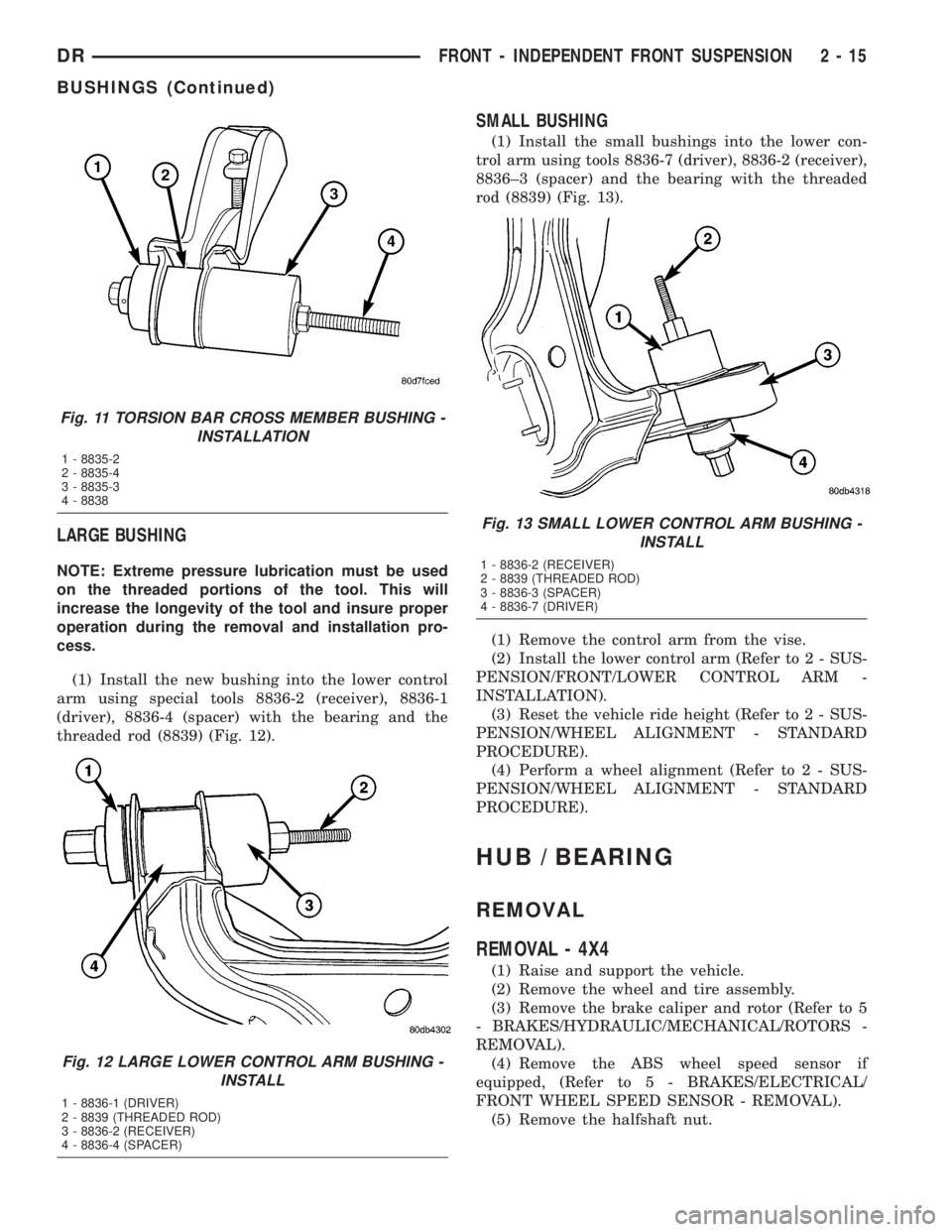
(1) Install the new bushing into the cross member
using special tools 8835-2, 8835-4 and 8835-3 with
the bearing and the threaded rod 8838 (Fig. 11) mak-
ing sure to properly orient the bushing.
(2) Remove the cross member from the vise.
(3) Install the torsion bar cross member (Refer to
13 - FRAME & BUMPERS/FRAME/REAR CROSS-
MEMBER - INSTALLATION).
(4) Reset the vehicle ride height (Refer to 2 - SUS-
PENSION/WHEEL ALIGNMENT - STANDARD
PROCEDURE).
(5) Perform a wheel alignment (Refer to 2 - SUS-
PENSION/WHEEL ALIGNMENT - STANDARD
PROCEDURE).
INSTALLATION - LOWER CONTROL ARM
BUSHINGS - 2WD (LD)
NOTE: HD 4X2 bushings are not servicable.
Fig. 9 FRAME BUSHING INSTALL
1 - THREADED ROD
2 - BEARINGS
3 - 8682-3 (RECEIVER)
4 - BUSHING
5 - 8682-1 (DRIVER)
Fig. 10 CONTROL ARM BUSHING INSTALL
1 - THREADED ROD
2 - BEARINGS
3 - 8682-1 (DRIVER)
4 - BUSHING
5 - CONTROL ARM
6 - 8682-5 (RECEIVER)
7 - NUT
2 - 14 FRONT - INDEPENDENT FRONT SUSPENSIONDR
BUSHINGS (Continued)
Page 44 of 2895
LARGE BUSHING
NOTE: Extreme pressure lubrication must be used
on the threaded portions of the tool. This will
increase the longevity of the tool and insure proper
operation during the removal and installation pro-
cess.
(1) Install the new bushing into the lower control
arm using special tools 8836-2 (receiver), 8836-1
(driver), 8836-4 (spacer) with the bearing and the
threaded rod (8839) (Fig. 12).
SMALL BUSHING
(1) Install the small bushings into the lower con-
trol arm using tools 8836-7 (driver), 8836-2 (receiver),
8836±3 (spacer) and the bearing with the threaded
rod (8839) (Fig. 13).
(1) Remove the control arm from the vise.
(2) Install the lower control arm (Refer to 2 - SUS-
PENSION/FRONT/LOWER CONTROL ARM -
INSTALLATION).
(3) Reset the vehicle ride height (Refer to 2 - SUS-
PENSION/WHEEL ALIGNMENT - STANDARD
PROCEDURE).
(4) Perform a wheel alignment (Refer to 2 - SUS-
PENSION/WHEEL ALIGNMENT - STANDARD
PROCEDURE).
HUB / BEARING
REMOVAL
REMOVAL - 4X4
(1) Raise and support the vehicle.
(2) Remove the wheel and tire assembly.
(3) Remove the brake caliper and rotor (Refer to 5
- BRAKES/HYDRAULIC/MECHANICAL/ROTORS -
REMOVAL).
(4) Remove the ABS wheel speed sensor if
equipped, (Refer to 5 - BRAKES/ELECTRICAL/
FRONT WHEEL SPEED SENSOR - REMOVAL).
(5) Remove the halfshaft nut.
Fig. 11 TORSION BAR CROSS MEMBER BUSHING -
INSTALLATION
1 - 8835-2
2 - 8835-4
3 - 8835-3
4 - 8838
Fig. 12 LARGE LOWER CONTROL ARM BUSHING -
INSTALL
1 - 8836-1 (DRIVER)
2 - 8839 (THREADED ROD)
3 - 8836-2 (RECEIVER)
4 - 8836-4 (SPACER)
Fig. 13 SMALL LOWER CONTROL ARM BUSHING -
INSTALL
1 - 8836-2 (RECEIVER)
2 - 8839 (THREADED ROD)
3 - 8836-3 (SPACER)
4 - 8836-7 (DRIVER)
DRFRONT - INDEPENDENT FRONT SUSPENSION 2 - 15
BUSHINGS (Continued)
Page 52 of 2895
SHOCK
DIAGNOSIS AND TESTING - SHOCK
A knocking or rattling noise from a shock absorber
may be caused by movement between mounting
bushings and metal brackets or attaching compo-
nents. These noises can usually be stopped by tight-
ening the attaching nuts. If the noise persists,
inspect for damaged and worn bushings, and attach-
ing components. Repair as necessary if any of these
conditions exist.
A squeaking noise from the shock absorber may be
caused by the hydraulic valving and may be intermit-
tent. This condition is not repairable and the shock
absorber must be replaced.
The shock absorbers are not refillable or adjust-
able. If a malfunction occurs, the shock absorber
must be replaced. To test a shock absorber, hold it in
an upright position and force the piston in and out of
the cylinder four or five times. The action throughout
each stroke should be smooth and even.
The shock absorber bushings do not require any
type of lubrication. Do not attempt to stop bushing
noise by lubricating them. Grease and mineral oil-
base lubricants will deteriorate the bushing.
REMOVAL
REMOVAL - 4X2
(1) Raise and support vehicle.
(2) Support the lower control arm outboard end.
(3) Remove the upper shock absorber nut, retainer
and grommet.
(4) Remove the lower nuts and remove the shock
absorber.
REMOVAL - 4X4
(1) Raise and support the vehicle.
(2) Remove the tire and wheel assembly.
(3) Support the lower control arm outboard end.
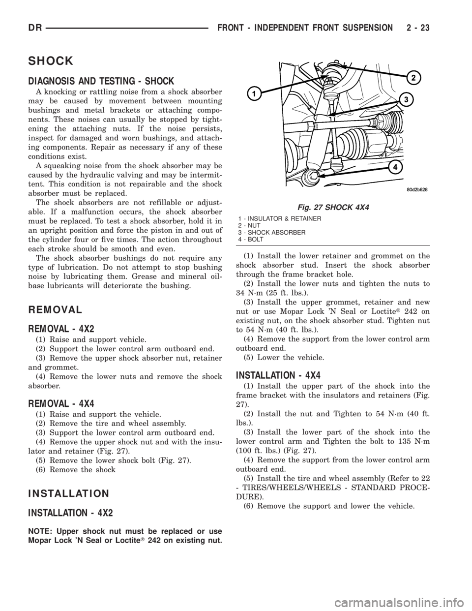
(4) Remove the upper shock nut and with the insu-
lator and retainer (Fig. 27).
(5) Remove the lower shock bolt (Fig. 27).
(6) Remove the shock
INSTALLATION
INSTALLATION - 4X2
NOTE: Upper shock nut must be replaced or use
Mopar Lock 'N Seal or LoctiteT242 on existing nut.(1) Install the lower retainer and grommet on the
shock absorber stud. Insert the shock absorber
through the frame bracket hole.
(2) Install the lower nuts and tighten the nuts to
34 N´m (25 ft. lbs.).
(3) Install the upper grommet, retainer and new
nut or use Mopar Lock 'N Seal or Loctitet242 on
existing nut, on the shock absorber stud. Tighten nut
to 54 N´m (40 ft. lbs.).
(4) Remove the support from the lower control arm
outboard end.
(5) Lower the vehicle.
INSTALLATION - 4X4
(1) Install the upper part of the shock into the
frame bracket with the insulators and retainers (Fig.
27).
(2) Install the nut and Tighten to 54 N´m (40 ft.
lbs.).
(3) Install the lower part of the shock into the
lower control arm and Tighten the bolt to 135 N´m
(100 ft. lbs.) (Fig. 27).
(4) Remove the support from the lower control arm
outboard end.
(5) Install the tire and wheel assembly (Refer to 22
- TIRES/WHEELS/WHEELS - STANDARD PROCE-
DURE).
(6) Remove the support and lower the vehicle.
Fig. 27 SHOCK 4X4
1 - INSULATOR & RETAINER
2 - NUT
3 - SHOCK ABSORBER
4 - BOLT
DRFRONT - INDEPENDENT FRONT SUSPENSION 2 - 23
Page 53 of 2895
STABILIZER BAR
DESCRIPTION
The bar extends across the front underside of the
chassis and connects to the frame crossmember. The
ends of the bar mount to the lower suspension arm.
All mounting points of the stabilizer bar are isolated
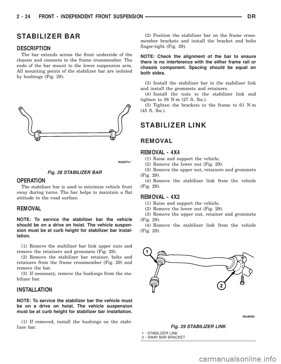
by bushings (Fig. 28).
OPERATION
The stabilizer bar is used to minimize vehicle front
sway during turns. The bar helps to maintain a flat
attitude to the road surface.
REMOVAL
NOTE: To service the stabilizer bar the vehicle
should be on a drive on hoist. The vehicle suspen-
sion must be at curb height for stabilizer bar instal-
lation.
(1) Remove the stabilizer bar link upper nuts and
remove the retainers and grommets (Fig. 29).
(2) Remove the stabilizer bar retainer, bolts and
retainers from the frame crossmember (Fig. 29) and
remove the bar.
(3) If necessary, remove the bushings from the sta-
bilizer bar.
INSTALLATION
NOTE: To service the stabilizer bar the vehicle must
be on a drive on hoist. The vehicle suspension
must be at curb height for stabilizer bar installation.
(1) If removed, install the bushings on the stabi-
lizer bar.(2) Position the stabilizer bar on the frame cross-
member brackets and install the bracket and bolts
finger-tight (Fig. 29).
NOTE: Check the alignment of the bar to ensure
there is no interference with the either frame rail or
chassis component. Spacing should be equal on
both sides.
(3) Install the stabilizer bar to the stabilizer link
and install the grommets and retainers.
(4) Install the nuts to the stabilizer link and
tighten to 38 N´m (27 ft. lbs.).
(5) Tighten the brackets to the frame to 61 N´m
(45 ft. lbs.).
STABILIZER LINK
REMOVAL
REMOVAL - 4X4
(1) Raise and support the vehicle.
(2) Remove the lower nut (Fig. 29).
(3) Remove the upper nut, retainers and grommets
(Fig. 29).
(4) Remove the stabilizer link from the vehicle
(Fig. 29).
REMOVAL - 4X2
(1) Raise and support the vehicle.
(2) Remove the lower nut (Fig. 29).
(3) Remove the upper nut, retainer and grommets
(Fig. 29).
(4) Remove the stabilizer link from the vehicle
(Fig. 29).
Fig. 28 STABILIZER BAR
Fig. 29 STABILIZER LINK
1 - STABILIZER LINK
2 - SWAY BAR BRACKET
2 - 24 FRONT - INDEPENDENT FRONT SUSPENSIONDR