bushing DODGE RAM 2003 Service Owner's Manual
[x] Cancel search | Manufacturer: DODGE, Model Year: 2003, Model line: RAM, Model: DODGE RAM 2003Pages: 2895, PDF Size: 83.15 MB
Page 242 of 2895
ASSEMBLY
CAUTION: Dirt, oil, and solvents can damage cali-
per seals. Insure assembly area is clean and dry.
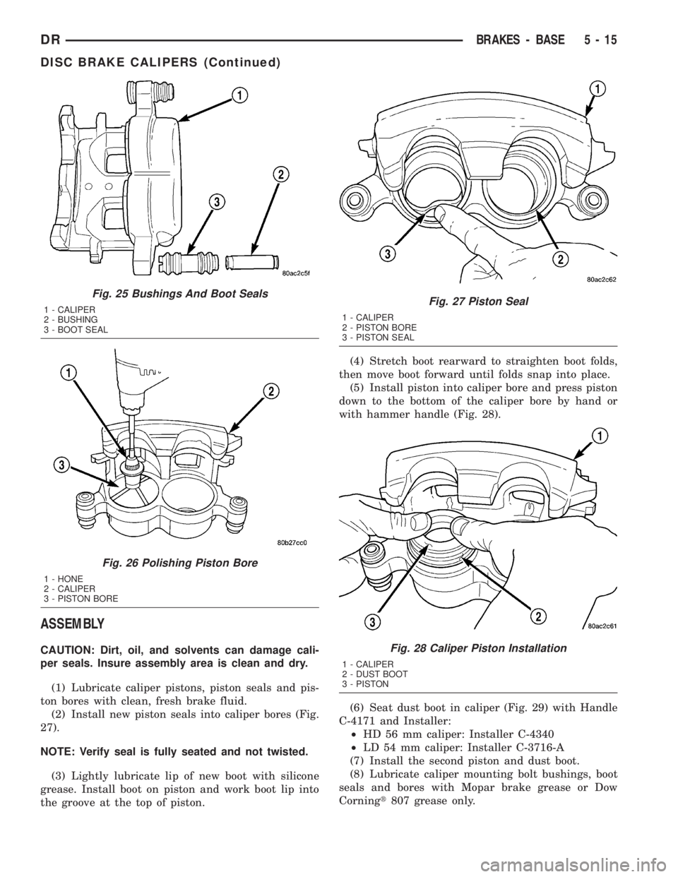
(1) Lubricate caliper pistons, piston seals and pis-
ton bores with clean, fresh brake fluid.
(2) Install new piston seals into caliper bores (Fig.
27).
NOTE: Verify seal is fully seated and not twisted.
(3) Lightly lubricate lip of new boot with silicone
grease. Install boot on piston and work boot lip into
the groove at the top of piston.(4) Stretch boot rearward to straighten boot folds,
then move boot forward until folds snap into place.
(5) Install piston into caliper bore and press piston
down to the bottom of the caliper bore by hand or
with hammer handle (Fig. 28).
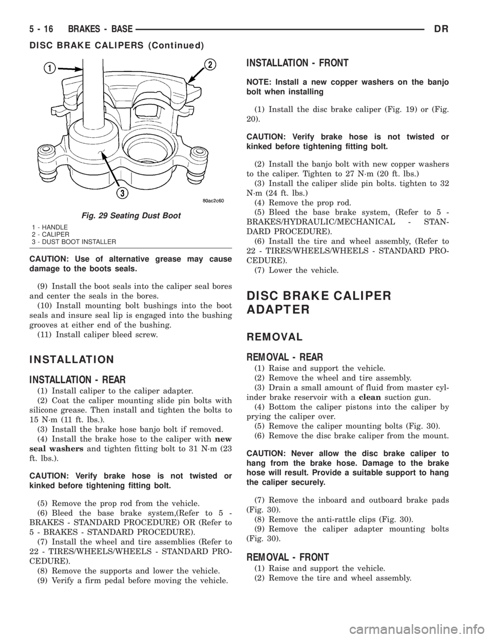
(6) Seat dust boot in caliper (Fig. 29) with Handle
C-4171 and Installer:
²HD 56 mm caliper: Installer C-4340
²LD 54 mm caliper: Installer C-3716-A
(7) Install the second piston and dust boot.
(8) Lubricate caliper mounting bolt bushings, boot
seals and bores with Mopar brake grease or Dow
Corningt807 grease only.
Fig. 25 Bushings And Boot Seals
1 - CALIPER
2 - BUSHING
3 - BOOT SEAL
Fig. 26 Polishing Piston Bore
1 - HONE
2 - CALIPER
3 - PISTON BORE
Fig. 27 Piston Seal
1 - CALIPER
2 - PISTON BORE
3 - PISTON SEAL
Fig. 28 Caliper Piston Installation
1 - CALIPER
2 - DUST BOOT
3 - PISTON
DRBRAKES - BASE 5 - 15
DISC BRAKE CALIPERS (Continued)
Page 243 of 2895
CAUTION: Use of alternative grease may cause
damage to the boots seals.
(9) Install the boot seals into the caliper seal bores
and center the seals in the bores.
(10) Install mounting bolt bushings into the boot
seals and insure seal lip is engaged into the bushing
grooves at either end of the bushing.
(11) Install caliper bleed screw.
INSTALLATION
INSTALLATION - REAR
(1) Install caliper to the caliper adapter.
(2) Coat the caliper mounting slide pin bolts with
silicone grease. Then install and tighten the bolts to
15 N´m (11 ft. lbs.).
(3) Install the brake hose banjo bolt if removed.
(4) Install the brake hose to the caliper withnew
seal washersand tighten fitting bolt to 31 N´m (23
ft. lbs.).
CAUTION: Verify brake hose is not twisted or
kinked before tightening fitting bolt.
(5) Remove the prop rod from the vehicle.
(6) Bleed the base brake system,(Refer to 5 -
BRAKES - STANDARD PROCEDURE) OR (Refer to
5 - BRAKES - STANDARD PROCEDURE).
(7) Install the wheel and tire assemblies (Refer to
22 - TIRES/WHEELS/WHEELS - STANDARD PRO-
CEDURE).
(8) Remove the supports and lower the vehicle.
(9) Verify a firm pedal before moving the vehicle.
INSTALLATION - FRONT
NOTE: Install a new copper washers on the banjo
bolt when installing
(1) Install the disc brake caliper (Fig. 19) or (Fig.
20).
CAUTION: Verify brake hose is not twisted or
kinked before tightening fitting bolt.
(2) Install the banjo bolt with new copper washers
to the caliper. Tighten to 27 N´m (20 ft. lbs.)
(3) Install the caliper slide pin bolts. tighten to 32
N´m (24 ft. lbs.)
(4) Remove the prop rod.
(5) Bleed the base brake system, (Refer to 5 -
BRAKES/HYDRAULIC/MECHANICAL - STAN-
DARD PROCEDURE).
(6) Install the tire and wheel assembly, (Refer to
22 - TIRES/WHEELS/WHEELS - STANDARD PRO-
CEDURE).
(7) Lower the vehicle.
DISC BRAKE CALIPER
ADAPTER
REMOVAL
REMOVAL - REAR
(1) Raise and support the vehicle.
(2) Remove the wheel and tire assembly.
(3) Drain a small amount of fluid from master cyl-
inder brake reservoir with acleansuction gun.
(4) Bottom the caliper pistons into the caliper by
prying the caliper over.
(5) Remove the caliper mounting bolts (Fig. 30).
(6) Remove the disc brake caliper from the mount.
CAUTION: Never allow the disc brake caliper to
hang from the brake hose. Damage to the brake
hose will result. Provide a suitable support to hang
the caliper securely.
(7) Remove the inboard and outboard brake pads
(Fig. 30).
(8) Remove the anti-rattle clips (Fig. 30).
(9) Remove the caliper adapter mounting bolts
(Fig. 30).
REMOVAL - FRONT
(1) Raise and support the vehicle.
(2) Remove the tire and wheel assembly.
Fig. 29 Seating Dust Boot
1 - HANDLE
2 - CALIPER
3 - DUST BOOT INSTALLER
5 - 16 BRAKES - BASEDR
DISC BRAKE CALIPERS (Continued)
Page 249 of 2895
NOTE: Using care remove the master cylinder
directly forward in order not to dislodge the output
rod from its seat inside the booster.
INSTALLATION
INSTALLATION - ALL EXCEPT HYDROBOOST
NOTE: If master cylinder is replaced bleed cylinder
before installation.
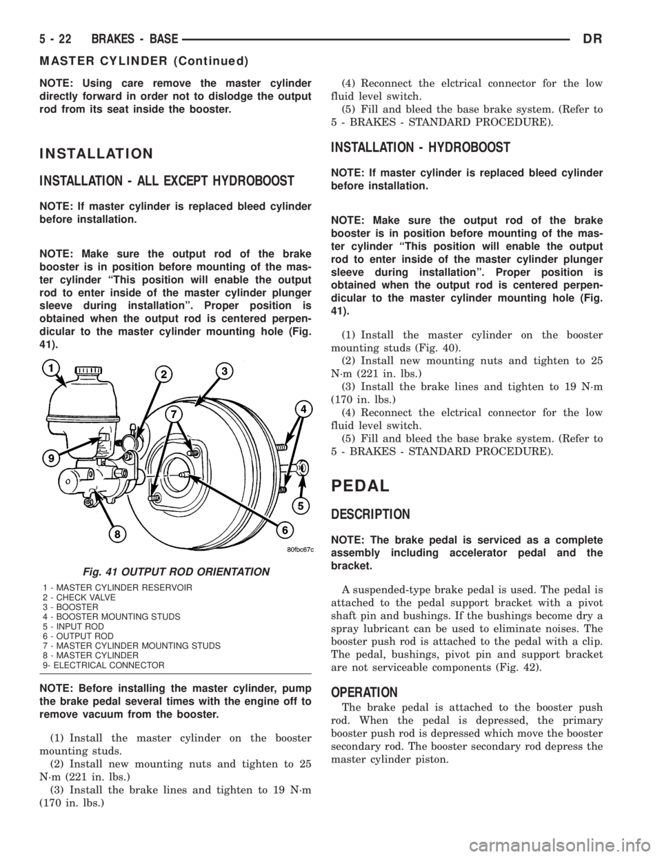
NOTE: Make sure the output rod of the brake
booster is in position before mounting of the mas-
ter cylinder ªThis position will enable the output
rod to enter inside of the master cylinder plunger
sleeve during installationº. Proper position is
obtained when the output rod is centered perpen-
dicular to the master cylinder mounting hole (Fig.
41).
NOTE: Before installing the master cylinder, pump
the brake pedal several times with the engine off to
remove vacuum from the booster.
(1) Install the master cylinder on the booster
mounting studs.
(2) Install new mounting nuts and tighten to 25
N´m (221 in. lbs.)
(3) Install the brake lines and tighten to 19 N´m
(170 in. lbs.)(4) Reconnect the elctrical connector for the low
fluid level switch.
(5) Fill and bleed the base brake system. (Refer to
5 - BRAKES - STANDARD PROCEDURE).
INSTALLATION - HYDROBOOST
NOTE: If master cylinder is replaced bleed cylinder
before installation.
NOTE: Make sure the output rod of the brake
booster is in position before mounting of the mas-
ter cylinder ªThis position will enable the output
rod to enter inside of the master cylinder plunger
sleeve during installationº. Proper position is
obtained when the output rod is centered perpen-
dicular to the master cylinder mounting hole (Fig.
41).
(1) Install the master cylinder on the booster
mounting studs (Fig. 40).
(2) Install new mounting nuts and tighten to 25
N´m (221 in. lbs.)
(3) Install the brake lines and tighten to 19 N´m
(170 in. lbs.)
(4) Reconnect the elctrical connector for the low
fluid level switch.
(5) Fill and bleed the base brake system. (Refer to
5 - BRAKES - STANDARD PROCEDURE).
PEDAL
DESCRIPTION
NOTE: The brake pedal is serviced as a complete
assembly including accelerator pedal and the
bracket.
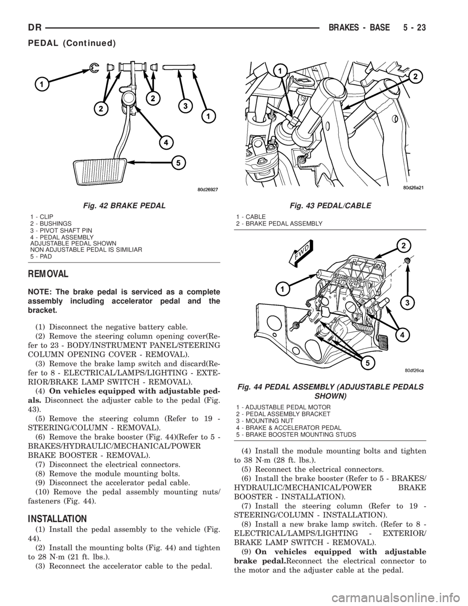
A suspended-type brake pedal is used. The pedal is
attached to the pedal support bracket with a pivot
shaft pin and bushings. If the bushings become dry a
spray lubricant can be used to eliminate noises. The
booster push rod is attached to the pedal with a clip.
The pedal, bushings, pivot pin and support bracket
are not serviceable components (Fig. 42).
OPERATION
The brake pedal is attached to the booster push
rod. When the pedal is depressed, the primary
booster push rod is depressed which move the booster
secondary rod. The booster secondary rod depress the
master cylinder piston.
Fig. 41 OUTPUT ROD ORIENTATION
1 - MASTER CYLINDER RESERVOIR
2 - CHECK VALVE
3 - BOOSTER
4 - BOOSTER MOUNTING STUDS
5 - INPUT ROD
6 - OUTPUT ROD
7 - MASTER CYLINDER MOUNTING STUDS
8 - MASTER CYLINDER
9- ELECTRICAL CONNECTOR
5 - 22 BRAKES - BASEDR
MASTER CYLINDER (Continued)
Page 250 of 2895
REMOVAL
NOTE: The brake pedal is serviced as a complete
assembly including accelerator pedal and the
bracket.
(1) Disconnect the negative battery cable.
(2) Remove the steering column opening cover(Re-
fer to 23 - BODY/INSTRUMENT PANEL/STEERING
COLUMN OPENING COVER - REMOVAL).
(3) Remove the brake lamp switch and discard(Re-
fer to 8 - ELECTRICAL/LAMPS/LIGHTING - EXTE-
RIOR/BRAKE LAMP SWITCH - REMOVAL).
(4)On vehicles equipped with adjustable ped-
als.Disconnect the adjuster cable to the pedal (Fig.
43).
(5) Remove the steering column (Refer to 19 -
STEERING/COLUMN - REMOVAL).
(6) Remove the brake booster (Fig. 44)(Refer to 5 -
BRAKES/HYDRAULIC/MECHANICAL/POWER
BRAKE BOOSTER - REMOVAL).
(7) Disconnect the electrical connectors.
(8) Remove the module mounting bolts.
(9) Disconnect the accelerator pedal cable.
(10) Remove the pedal assembly mounting nuts/
fasteners (Fig. 44).
INSTALLATION
(1) Install the pedal assembly to the vehicle (Fig.
44).
(2) Install the mounting bolts (Fig. 44) and tighten
to 28 N´m (21 ft. lbs.).
(3) Reconnect the accelerator cable to the pedal.(4) Install the module mounting bolts and tighten
to 38 N´m (28 ft. lbs.).
(5) Reconnect the electrical connectors.
(6) Install the brake booster (Refer to 5 - BRAKES/
HYDRAULIC/MECHANICAL/POWER BRAKE
BOOSTER - INSTALLATION).
(7) Install the steering column (Refer to 19 -
STEERING/COLUMN - INSTALLATION).
(8) Install a new brake lamp switch. (Refer to 8 -
ELECTRICAL/LAMPS/LIGHTING - EXTERIOR/
BRAKE LAMP SWITCH - REMOVAL).
(9)On vehicles equipped with adjustable
brake pedal.Reconnect the electrical connector to
the motor and the adjuster cable at the pedal.
Fig. 42 BRAKE PEDAL
1 - CLIP
2 - BUSHINGS
3 - PIVOT SHAFT PIN
4 - PEDAL ASSEMBLY
ADJUSTABLE PEDAL SHOWN
NON ADJUSTABLE PEDAL IS SIMILIAR
5-PAD
Fig. 43 PEDAL/CABLE
1 - CABLE
2 - BRAKE PEDAL ASSEMBLY
Fig. 44 PEDAL ASSEMBLY (ADJUSTABLE PEDALS
SHOWN)
1 - ADJUSTABLE PEDAL MOTOR
2 - PEDAL ASSEMBLY BRACKET
3 - MOUNTING NUT
4 - BRAKE & ACCELERATOR PEDAL
5 - BRAKE BOOSTER MOUNTING STUDS
DRBRAKES - BASE 5 - 23
PEDAL (Continued)
Page 278 of 2895
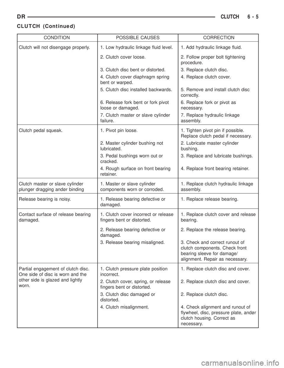
CONDITION POSSIBLE CAUSES CORRECTION
Clutch will not disengage properly. 1. Low hydraulic linkage fluid level. 1. Add hydraulic linkage fluid.
2. Clutch cover loose. 2. Follow proper bolt tightening
procedure.
3. Clutch disc bent or distorted. 3. Replace clutch disc.
4. Clutch cover diaphragm spring
bent or warped.4. Replace clutch cover.
5. Clutch disc installed backwards. 5. Remove and install clutch disc
correctly.
6. Release fork bent or fork pivot
loose or damaged.6. Replace fork or pivot as
necessary.
7. Clutch master or slave cylinder
failure.7. Replace hydraulic linkage
assembly.
Clutch pedal squeak. 1. Pivot pin loose. 1. Tighten pivot pin if possible.
Replace clutch pedal if necessary.
2. Master cylinder bushing not
lubricated.2. Lubricate master cylinder
bushing.
3. Pedal bushings worn out or
cracked.3. Replace and lubricate bushings.
4. Rough surface on front bearing
retainer.4. Replace front bearing retainer.
Clutch master or slave cylinder
plunger dragging andùr binding1. Master or slave cylinder
components worn or corroded.1. Replace clutch hydraulic linkage
assembly.
Release bearing is noisy. 1. Release bearing defective or
damaged.1. Replace release bearing.
Contact surface of release bearing
damaged.1. Clutch cover incorrect or release
fingers bent or distorted.1. Replace clutch cover and release
bearing.
2. Release bearing defective or
damaged.2. Replace the release bearing.
3. Release bearing misaligned. 3. Check and correct runout of
clutch components. Check front
bearing sleeve for damage/
alignment. Repair as necessary.
Partial engagement of clutch disc.
One side of disc is worn and the
other side is glazed and lightly
worn.1. Clutch pressure plate position
incorrect.1. Replace clutch disc and cover.
2. Clutch cover, spring, or release
fingers bent or distorted.2. Replace clutch disc and cover.
3. Clutch disc damaged or
distorted.2. Replace clutch disc.
4. Clutch misalignment. 4. Check alignment and runout of
flywheel, disc, pressure plate, andùr
clutch housing. Correct as
necessary.
DRCLUTCH 6 - 5
CLUTCH (Continued)
Page 279 of 2895
SPECIFICATIONS
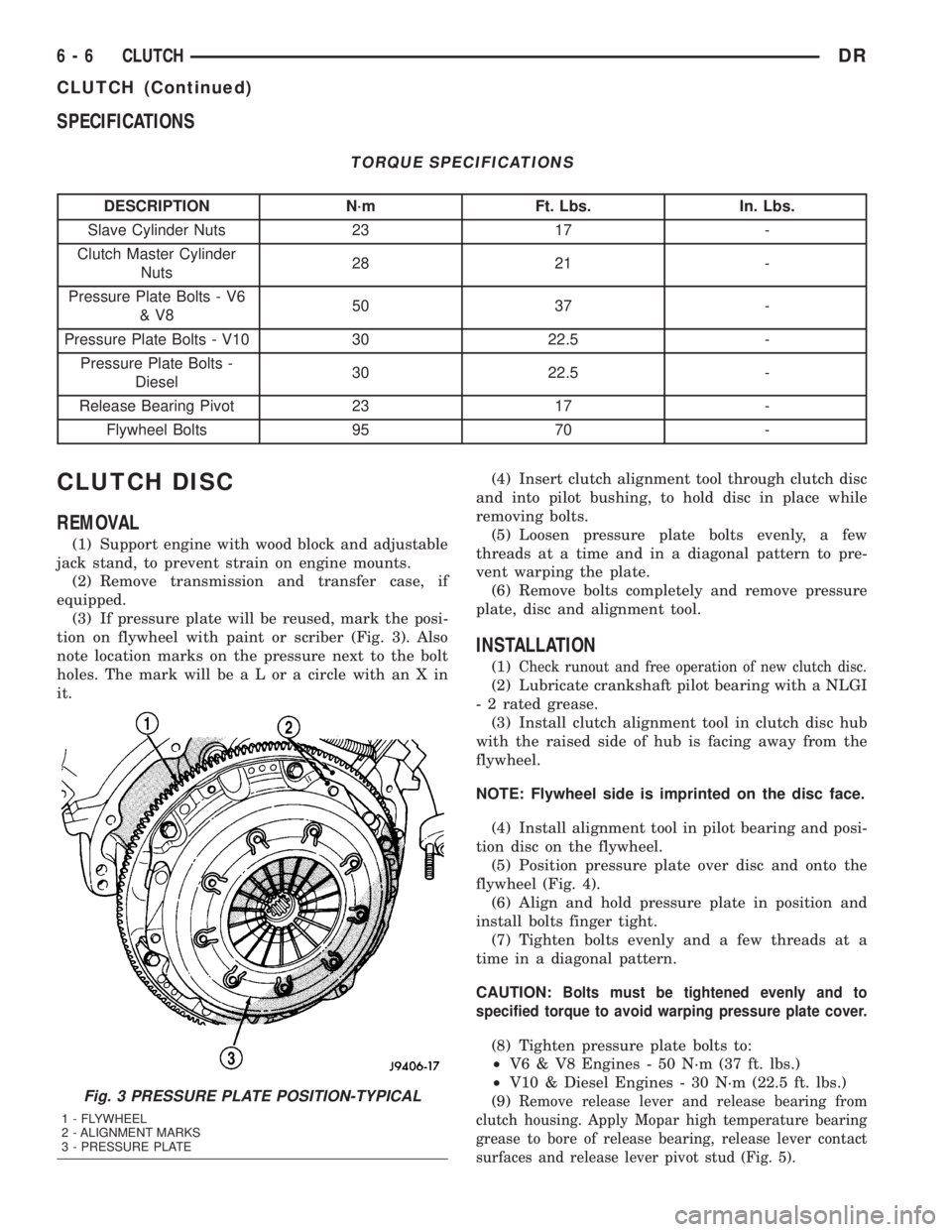
TORQUE SPECIFICATIONS
DESCRIPTION N´m Ft. Lbs. In. Lbs.
Slave Cylinder Nuts 23 17 -
Clutch Master Cylinder
Nuts28 21 -
Pressure Plate Bolts - V6
&V850 37 -
Pressure Plate Bolts - V10 30 22.5 -
Pressure Plate Bolts -
Diesel30 22.5 -
Release Bearing Pivot 23 17 -
Flywheel Bolts 95 70 -
CLUTCH DISC
REMOVAL
(1) Support engine with wood block and adjustable
jack stand, to prevent strain on engine mounts.
(2) Remove transmission and transfer case, if
equipped.
(3) If pressure plate will be reused, mark the posi-
tion on flywheel with paint or scriber (Fig. 3). Also
note location marks on the pressure next to the bolt
holes. The mark will be a L or a circle with an X in
it.(4) Insert clutch alignment tool through clutch disc
and into pilot bushing, to hold disc in place while
removing bolts.
(5) Loosen pressure plate bolts evenly, a few
threads at a time and in a diagonal pattern to pre-
vent warping the plate.
(6) Remove bolts completely and remove pressure
plate, disc and alignment tool.
INSTALLATION
(1)Check runout and free operation of new clutch disc.
(2) Lubricate crankshaft pilot bearing with a NLGI
- 2 rated grease.
(3) Install clutch alignment tool in clutch disc hub
with the raised side of hub is facing away from the
flywheel.
NOTE: Flywheel side is imprinted on the disc face.
(4) Install alignment tool in pilot bearing and posi-
tion disc on the flywheel.
(5) Position pressure plate over disc and onto the
flywheel (Fig. 4).
(6) Align and hold pressure plate in position and
install bolts finger tight.
(7) Tighten bolts evenly and a few threads at a
time in a diagonal pattern.
CAUTION:
Bolts must be tightened evenly and to
specified torque to avoid warping pressure plate cover.
(8) Tighten pressure plate bolts to:
²V6 & V8 Engines - 50 N´m (37 ft. lbs.)
²V10 & Diesel Engines - 30 N´m (22.5 ft. lbs.)
(9)
Remove release lever and release bearing from
clutch housing. Apply Mopar high temperature bearing
grease to bore of release bearing, release lever contact
surfaces and release lever pivot stud (Fig. 5).Fig. 3 PRESSURE PLATE POSITION-TYPICAL
1 - FLYWHEEL
2 - ALIGNMENT MARKS
3 - PRESSURE PLATE
6 - 6 CLUTCHDR
CLUTCH (Continued)
Page 335 of 2895
OPERATION
The wax pellet is located in a sealed container at
the spring end of the thermostat. When heated, the
pellet expands, overcoming closing spring tension
and water pump pressure to force the valve to open.
DIAGNOSIS AND TESTINGÐTHERMOSTAT
ON-BOARD DIAGNOSTICS
Allgasoline powered modelsare equipped with
On-Board Diagnostics for certain cooling system com-
ponents. Refer to On-Board Diagnostics (OBD) in the
Diagnosis section of this group for additional infor-
mation. If the powertrain control module (PCM)
detects low engine coolant temperature, it will record
a Diagnostic Trouble Code (DTC) in the PCM mem-
ory. Do not change a thermostat for lack of heat as
indicated by the instrument panel gauge or by poor
heater performance unless a DTC is present. Refer to
the Diagnosis section of this group for other probable
causes.
The DTC can also be accessed through the
DRBIIItscan tool. Refer to the appropriate Power-
train Diagnostic Procedures information for diagnos-
tic information and operation of the DRBIIItscan
tool.
REMOVAL
WARNING: DO NOT LOOSEN THE RADIATOR
DRAINCOCK WITH THE COOLING SYSTEM HOT
AND PRESSURIZED. SERIOUS BURNS FROM THE
COOLANT CAN OCCUR.
Do not waste reusable coolant. If the solution is
clean, drain the coolant into a clean container for
reuse.
If the thermostat is being replaced, be sure that
the replacement is the specified thermostat for the
vehicle model and engine type.
Factory installed thermostat housings on 5.9L
engine is installed on a gasket with an anti-stick
coating. This will aid in gasket removal and clean-up.
(1) Disconnect the negative battery cable.
(2) Drain the cooling system until the coolant level
is below the thermostat (Refer to 7 - COOLING -
STANDARD PROCEDURE).
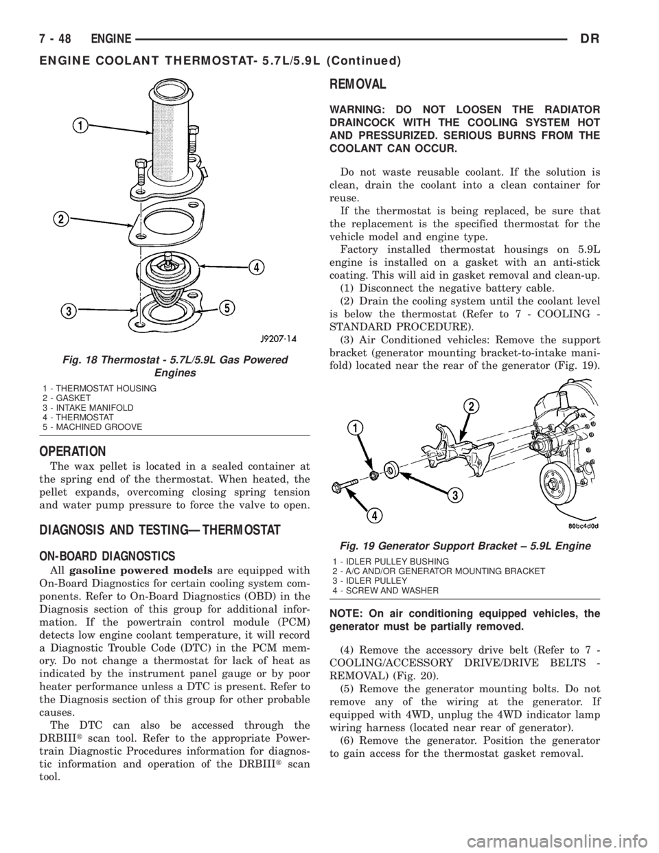
(3) Air Conditioned vehicles: Remove the support
bracket (generator mounting bracket-to-intake mani-
fold) located near the rear of the generator (Fig. 19).
NOTE: On air conditioning equipped vehicles, the
generator must be partially removed.
(4) Remove the accessory drive belt (Refer to 7 -
COOLING/ACCESSORY DRIVE/DRIVE BELTS -
REMOVAL) (Fig. 20).
(5) Remove the generator mounting bolts. Do not
remove any of the wiring at the generator. If
equipped with 4WD, unplug the 4WD indicator lamp
wiring harness (located near rear of generator).
(6) Remove the generator. Position the generator
to gain access for the thermostat gasket removal.
Fig. 18 Thermostat - 5.7L/5.9L Gas Powered
Engines
1 - THERMOSTAT HOUSING
2 - GASKET
3 - INTAKE MANIFOLD
4 - THERMOSTAT
5 - MACHINED GROOVE
Fig. 19 Generator Support Bracket ± 5.9L Engine
1 - IDLER PULLEY BUSHING
2 - A/C AND/OR GENERATOR MOUNTING BRACKET
3 - IDLER PULLEY
4 - SCREW AND WASHER
7 - 48 ENGINEDR
ENGINE COOLANT THERMOSTAT- 5.7L/5.9L (Continued)
Page 697 of 2895
WIPER MODULE
DESCRIPTION
The wiper motor bracket is secured with two
screws below the wiper motor through two rubber
insulators to the bottom of the cowl plenum panel
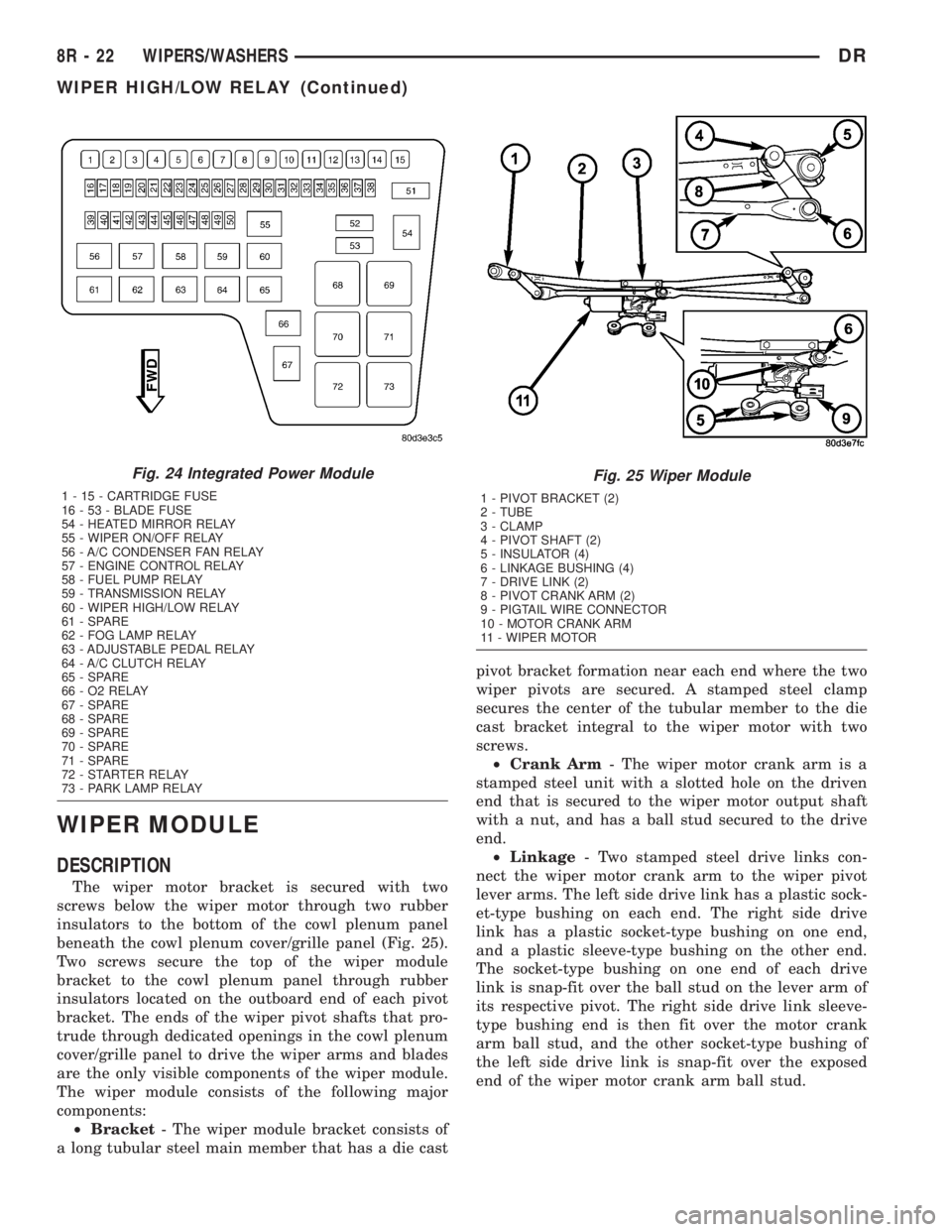
beneath the cowl plenum cover/grille panel (Fig. 25).
Two screws secure the top of the wiper module
bracket to the cowl plenum panel through rubber
insulators located on the outboard end of each pivot
bracket. The ends of the wiper pivot shafts that pro-
trude through dedicated openings in the cowl plenum
cover/grille panel to drive the wiper arms and blades
are the only visible components of the wiper module.
The wiper module consists of the following major
components:
²Bracket- The wiper module bracket consists of
a long tubular steel main member that has a die castpivot bracket formation near each end where the two
wiper pivots are secured. A stamped steel clamp
secures the center of the tubular member to the die
cast bracket integral to the wiper motor with two
screws.
²Crank Arm- The wiper motor crank arm is a
stamped steel unit with a slotted hole on the driven
end that is secured to the wiper motor output shaft
with a nut, and has a ball stud secured to the drive
end.
²Linkage- Two stamped steel drive links con-
nect the wiper motor crank arm to the wiper pivot
lever arms. The left side drive link has a plastic sock-
et-type bushing on each end. The right side drive
link has a plastic socket-type bushing on one end,
and a plastic sleeve-type bushing on the other end.
The socket-type bushing on one end of each drive
link is snap-fit over the ball stud on the lever arm of
its respective pivot. The right side drive link sleeve-
type bushing end is then fit over the motor crank
arm ball stud, and the other socket-type bushing of
the left side drive link is snap-fit over the exposed
end of the wiper motor crank arm ball stud.
Fig. 24 Integrated Power Module
1 - 15 - CARTRIDGE FUSE
16 - 53 - BLADE FUSE
54 - HEATED MIRROR RELAY
55 - WIPER ON/OFF RELAY
56 - A/C CONDENSER FAN RELAY
57 - ENGINE CONTROL RELAY
58 - FUEL PUMP RELAY
59 - TRANSMISSION RELAY
60 - WIPER HIGH/LOW RELAY
61 - SPARE
62 - FOG LAMP RELAY
63 - ADJUSTABLE PEDAL RELAY
64 - A/C CLUTCH RELAY
65 - SPARE
66 - O2 RELAY
67 - SPARE
68 - SPARE
69 - SPARE
70 - SPARE
71 - SPARE
72 - STARTER RELAY
73 - PARK LAMP RELAY
Fig. 25 Wiper Module
1 - PIVOT BRACKET (2)
2 - TUBE
3 - CLAMP
4 - PIVOT SHAFT (2)
5 - INSULATOR (4)
6 - LINKAGE BUSHING (4)
7 - DRIVE LINK (2)
8 - PIVOT CRANK ARM (2)
9 - PIGTAIL WIRE CONNECTOR
10 - MOTOR CRANK ARM
11 - WIPER MOTOR
8R - 22 WIPERS/WASHERSDR
WIPER HIGH/LOW RELAY (Continued)
Page 698 of 2895
²Motor- The wiper motor features an integral
die cast bracket to which the wiper module bracket is
secured with a stamped steel clamp and two screws
near the top and which has two rubber insulated
mounting ears at the bottom. This die casting also
serves as the wiper motor transmission housing from
which the wiper motor output shaft exits. A nut
secures the wiper motor crank arm to the motor out-
put shaft. The two-speed permanent magnet wiper
motor features an integral transmission, an internal
park switch, and an internal automatic resetting cir-
cuit breaker.
²Pivots- The two front wiper pivots are secured
within the die cast pivot brackets on the outboard
ends of the wiper module main member. The lever
arms that extend from the center of the pivot shafts
each have a ball stud on their end. The upper end of
each pivot shaft where the wiper arms will be fas-
tened each has a serrated driver with a keyway. The
lower ends of the pivot shafts are installed through
lubricated bushings in the pivot brackets and are
secured with snap rings.
The wiper module cannot be adjusted or repaired.
If any component of the module is faulty or damaged,
the entire wiper module unit must be replaced.
OPERATION
The wiper module operation is controlled by the
battery current inputs received by the wiper motor
through the wiper on/off and wiper high/low relays.
The wiper motor speed is controlled by current flow
to either the low speed or the high speed set of
brushes. The park switch is a single pole, single
throw, momentary switch within the wiper motor
that is mechanically actuated by the wiper motor
transmission components. The park switch alter-
nately opens and closes the wiper park switch sense
circuit to ground, depending upon the position of the
wipers on the glass. This feature allows the motor to
complete its current wipe cycle after the wiper sys-
tem has been turned Off, and to park the wiper
blades in the lowest portion of the wipe pattern. The
automatic resetting circuit breaker protects the
motor from overloads. The wiper motor crank arm,
the two wiper linkage members, and the two wiper
pivots mechanically convert the rotary output of the
wiper motor to the back and forth wiping motion of
the wiper arms and blades on the glass.
REMOVAL
(1) Remove both wiper arms from the wiper pivots.
(Refer to 8 - ELECTRICAL/WIPERS/WASHERS/
WIPER ARM - REMOVAL).
(2) Unlatch and open the hood.
(3) Disconnect and isolate the battery negative
cable.
(4) Remove the cowl plenum cover/grille panel
from over the cowl plenum. (Refer to 23 - BODY/EX-
TERIOR/COWL GRILLE - REMOVAL).
(5) Disconnect the left headlamp and dash wire
harness connector for the wiper motor from the
motor pigtail wire connector (Fig. 26).
(6) Remove the two screws that secure the wiper
module to the top of the cowl plenum panel at the
pivot brackets.
(7) Remove the two screws that secure the wiper
module to the bottom of the cowl plenum panel.
(8) Remove the wiper module from the cowl ple-
num panel as a unit.
INSTALLATION
(1) Position the wiper module into the cowl ple-
num as a unit (Fig. 26).
(2) Install the two screws that secure the wiper
module to the top of the cowl plenum panel at the
pivot brackets. Tighten the screw on the driver side,
followed by the screw on the passenger side. Tighten
the screws to 7 N´m (60 in. lbs.).
(3) Install and tighten the screws that secure the
wiper module to the bottom of the cowl plenum
panel. Tighten the screw on the passenger side, fol-
lowed by the screw on the driver side. Tighten the
screws to 7 N´m (60 in. lbs.).
(4) Reconnect the left headlamp and dash wire
harness connector for the wiper motor to the motor
pigtail wire connector.
(5) Reinstall the cowl plenum cover/grille panel
over the cowl plenum. (Refer to 23 - BODY/EXTERI-
OR/COWL GRILLE - INSTALLATION).
(6) Reconnect the battery negative cable.
(7) Close and latch the hood.
(8) Reinstall both wiper arms onto the wiper piv-
ots. (Refer to 8 - ELECTRICAL/WIPERS/WASHERS/
WIPER ARMS - INSTALLATION).
DRWIPERS/WASHERS 8R - 23
WIPER MODULE (Continued)
Page 1325 of 2895
The idler shaft is a light press-fit into the cylinder
block. A large washer on the idler shaft bolt and the
rear flange of the idler shaft are used to control
sprocket thrust movement. Pressurized oil is routed
through the center of the idler shaft to provide lubri-
cation for the two bushings used in the idler sprocket
assembly.
There are two secondary drive chains, both are
roller type, one to drive the camshaft in each SOHC
cylinder head. There are no shaft speed changes in
the secondary chain drive system. Each secondary
chain drives a 26 tooth cam sprocket directly from
the 26 tooth sprocket on the idler sprocket assembly.
A fixed chain guide and a hydraulic oil damped ten-
sioner are used to maintain tension in each second-
ary chain system. The hydraulic tensioners for the
secondary chain systems are fed pressurized oil from
oil reservoir pockets in the block. Each tensioner
incorporates a controlled leak path through a device
known as a vent disc located in the nose of the piston
to manage chain loads. Each tensioner also has a
mechanical ratchet system that limits chain slack if
the tensioner piston bleeds down after engine shut
down. The tensioner arms and guides also utilize
nylon wear faces for low friction and long wear. The
secondary timing chains receive lubrication from a
small orifice in the tensioners. This orifice is pro-
tected from clogging by a fine mesh screen which is
located on the back of the hydraulic tensioners.
STANDARD PROCEDURE
MEASURING TIMING CHAIN WEAR
NOTE: This procedure must be performed with the
timing chain cover removed.
(1) Remove the timing chain cover. Refer to Timing
Chain Cover in this section for procedure.
(2) To determine if the secondary timing chains
are worn, rotate the engine clockwise until maximum
tensioner piston extension is obtained. Measure the
distance between the secondary timing chain ten-
sioner housing and the step ledge on the piston. The
measurement at point (A) must be less than 15mm
(.5906 inches).
(3) If the measurement exceeds the specification
the secondary timing chains are worn and require
replacement. Refer to Timing Chain and Sprockets in
this section for procedure.
SERVICE PROCEDURE - TIMING VERIFICATION
CAUTION: The 3.7L is a non free-wheeling design
engine. Therefore, correct engine timing is critical.NOTE: Components referred to as left hand or right
hand are as viewed from the drivers position inside
the vehicle.
NOTE: The blue link plates on the chains and the
dots on the camshaft drive sprockets may not line
up during the timing verification procedure. The
blue link plates are lined up with the sprocket dots
only when re-timing the complete timing drive.
Once the timing drive is rotated blue link-to-dot
alignment is no longer valid.
Engine base timing can be verified by the following
procedure:
(1) Remove the cylinder head covers. Refer to the
procedure in this section.
(2) Using a mirror, locate the TDC arrow on the
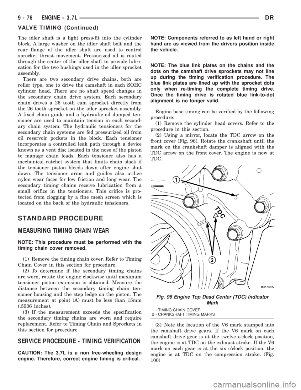
front cover (Fig. 96). Rotate the crankshaft until the
mark on the crankshaft damper is aligned with the
TDC arrow on the front cover. The engine is now at
TDC.
(3) Note the location of the V6 mark stamped into
the camshaft drive gears. If the V6 mark on each
camshaft drive gear is at the twelve o'clock position,
the engine is at TDC on the exhaust stroke. If the V6
mark on each gear is at the six o'clock position, the
engine is at TDC on the compression stroke. (Fig.
100)
Fig. 96 Engine Top Dead Center (TDC) Indicator
Mark
1 - TIMING CHAIN COVER
2 - CRANKSHAFT TIMING MARKS
9 - 76 ENGINE - 3.7LDR
VALVE TIMING (Continued)