bushing DODGE RAM 2003 Service Owner's Guide
[x] Cancel search | Manufacturer: DODGE, Model Year: 2003, Model line: RAM, Model: DODGE RAM 2003Pages: 2895, PDF Size: 83.15 MB
Page 1332 of 2895
(8) Remove the oil fill housing to gain access to the
right side tensioner arm fastener.
(9) Remove crankshaft damper (Refer to 9 -
ENGINE/ENGINE BLOCK/VIBRATION DAMPER -
REMOVAL) and timing chain cover(Refer to 9 -
ENGINE/VALVE TIMING/TIMING BELT / CHAIN
COVER(S) - REMOVAL).
(10) Collapse and pin primary chain tensioner.
CAUTION: Plate behind left secondary chain ten-
sioner could fall into oil pan. Therefore, cover pan
opening.
(11) Remove secondary chain tensioners.
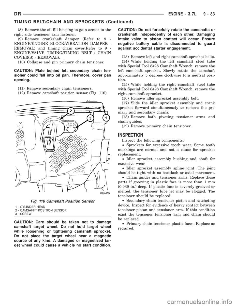
(12) Remove camshaft position sensor (Fig. 110).
CAUTION: Care should be taken not to damage
camshaft target wheel. Do not hold target wheel
while loosening or tightening camshaft sprocket.
Do not place the target wheel near a magnetic
source of any kind. A damaged or magnetized tar-
get wheel could cause a vehicle no start condition.CAUTION: Do not forcefully rotate the camshafts or
crankshaft independently of each other. Damaging
intake valve to piston contact will occur. Ensure
negative battery cable is disconnected to guard
against accidental starter engagement.
(13) Remove left and right camshaft sprocket bolts.
(14) While holding the left camshaft steel tube
with Special Tool 8428 Camshaft Wrench, remove the
left camshaft sprocket. Slowly rotate the camshaft
approximately 5 degrees clockwise to a neutral posi-
tion.
(15) While holding the right camshaft steel tube
with Special Tool 8428 Camshaft Wrench, remove the
right camshaft sprocket.
(16) Remove idler sprocket assembly bolt.
(17) Slide the idler sprocket assembly and crank
sprocket forward simultaneously to remove the pri-
mary and secondary chains.
(18) Remove both pivoting tensioner arms and
chain guides.
(19) Remove primary chain tensioner.
INSPECTION
Inspect the following components:
²Sprockets for excessive tooth wear. Some tooth
markings are normal and not a cause for sprocket
replacement.
²Idler sprocket assembly bushing and shaft for
excessive wear.
²Idler sprocket assembly spline joint. The joint
should be tight with no backlash or axial movement.
²Chain guides and tensioner arms. Replace these
parts if grooving in plastic face is more than 1 mm
(0.039 in.) deep. If plastic face is severely grooved or
melted, the tensioner lube jet may be clogged. The
tensioner should be replaced.
²Secondary chain tensioner piston and ratcheting
device. Inspect for evidence of heavy contact between
tensioner piston and tensioner arm. If this condition
exist the tensioner tensioner arm and chain should
be replaced.
²Primary chain tensioner plastic faces. Replace as
required.
Fig. 110 Camshaft Position Sensor
1 - CYLINDER HEAD
2 - CAMSAHFT POSITION SENSOR
3 - SCREW
DRENGINE - 3.7L 9 - 83
TIMING BELT/CHAIN AND SPROCKETS (Continued)
Page 1333 of 2895
INSTALLATION
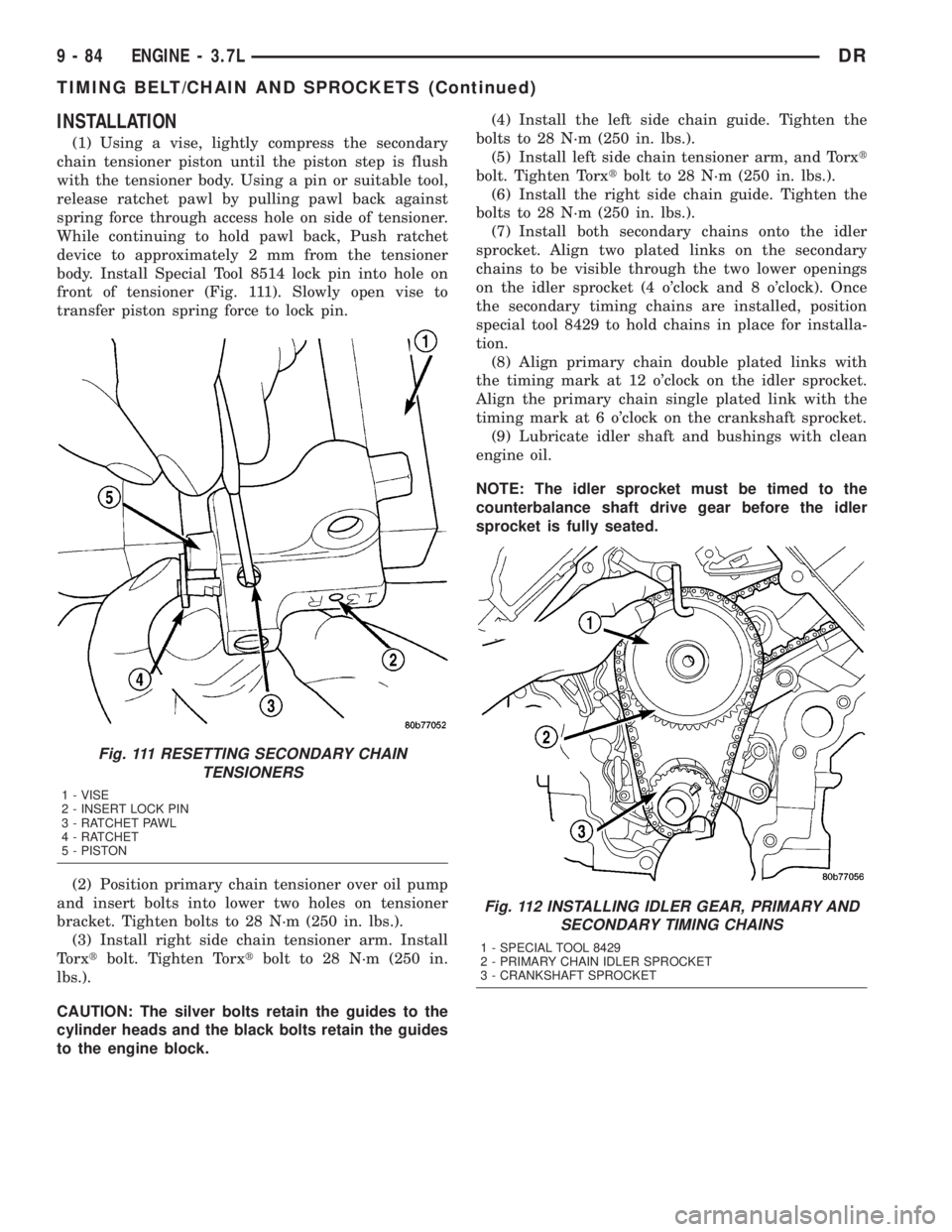
(1) Using a vise, lightly compress the secondary
chain tensioner piston until the piston step is flush
with the tensioner body. Using a pin or suitable tool,
release ratchet pawl by pulling pawl back against
spring force through access hole on side of tensioner.
While continuing to hold pawl back, Push ratchet
device to approximately 2 mm from the tensioner
body. Install Special Tool 8514 lock pin into hole on
front of tensioner (Fig. 111). Slowly open vise to
transfer piston spring force to lock pin.
(2) Position primary chain tensioner over oil pump
and insert bolts into lower two holes on tensioner
bracket. Tighten bolts to 28 N´m (250 in. lbs.).
(3) Install right side chain tensioner arm. Install
Torxtbolt. Tighten Torxtbolt to 28 N´m (250 in.
lbs.).
CAUTION: The silver bolts retain the guides to the
cylinder heads and the black bolts retain the guides
to the engine block.(4) Install the left side chain guide. Tighten the
bolts to 28 N´m (250 in. lbs.).
(5) Install left side chain tensioner arm, and Torxt
bolt. Tighten Torxtbolt to 28 N´m (250 in. lbs.).
(6) Install the right side chain guide. Tighten the
bolts to 28 N´m (250 in. lbs.).
(7) Install both secondary chains onto the idler
sprocket. Align two plated links on the secondary
chains to be visible through the two lower openings
on the idler sprocket (4 o'clock and 8 o'clock). Once
the secondary timing chains are installed, position
special tool 8429 to hold chains in place for installa-
tion.
(8) Align primary chain double plated links with
the timing mark at 12 o'clock on the idler sprocket.
Align the primary chain single plated link with the
timing mark at 6 o'clock on the crankshaft sprocket.
(9) Lubricate idler shaft and bushings with clean
engine oil.
NOTE: The idler sprocket must be timed to the
counterbalance shaft drive gear before the idler
sprocket is fully seated.
Fig. 111 RESETTING SECONDARY CHAIN
TENSIONERS
1 - VISE
2 - INSERT LOCK PIN
3 - RATCHET PAWL
4 - RATCHET
5 - PISTON
Fig. 112 INSTALLING IDLER GEAR, PRIMARY AND
SECONDARY TIMING CHAINS
1 - SPECIAL TOOL 8429
2 - PRIMARY CHAIN IDLER SPROCKET
3 - CRANKSHAFT SPROCKET
9 - 84 ENGINE - 3.7LDR
TIMING BELT/CHAIN AND SPROCKETS (Continued)
Page 1413 of 2895
VALVE TIMING
DESCRIPTIONÐTIMING DRIVE SYSTEM
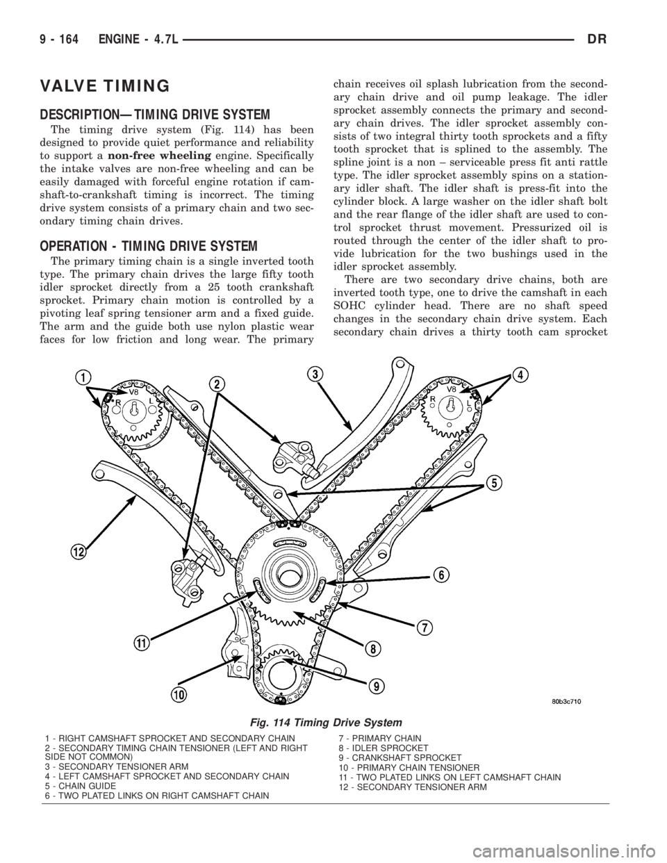
The timing drive system (Fig. 114) has been
designed to provide quiet performance and reliability
to support anon-free wheelingengine. Specifically
the intake valves are non-free wheeling and can be
easily damaged with forceful engine rotation if cam-
shaft-to-crankshaft timing is incorrect. The timing
drive system consists of a primary chain and two sec-
ondary timing chain drives.
OPERATION - TIMING DRIVE SYSTEM
The primary timing chain is a single inverted tooth
type. The primary chain drives the large fifty tooth
idler sprocket directly from a 25 tooth crankshaft
sprocket. Primary chain motion is controlled by a
pivoting leaf spring tensioner arm and a fixed guide.
The arm and the guide both use nylon plastic wear
faces for low friction and long wear. The primarychain receives oil splash lubrication from the second-
ary chain drive and oil pump leakage. The idler
sprocket assembly connects the primary and second-
ary chain drives. The idler sprocket assembly con-
sists of two integral thirty tooth sprockets and a fifty
tooth sprocket that is splined to the assembly. The
spline joint is a non ± serviceable press fit anti rattle
type. The idler sprocket assembly spins on a station-
ary idler shaft. The idler shaft is press-fit into the
cylinder block. A large washer on the idler shaft bolt
and the rear flange of the idler shaft are used to con-
trol sprocket thrust movement. Pressurized oil is
routed through the center of the idler shaft to pro-
vide lubrication for the two bushings used in the
idler sprocket assembly.
There are two secondary drive chains, both are
inverted tooth type, one to drive the camshaft in each
SOHC cylinder head. There are no shaft speed
changes in the secondary chain drive system. Each
secondary chain drives a thirty tooth cam sprocket
Fig. 114 Timing Drive System
1 - RIGHT CAMSHAFT SPROCKET AND SECONDARY CHAIN
2 - SECONDARY TIMING CHAIN TENSIONER (LEFT AND RIGHT
SIDE NOT COMMON)
3 - SECONDARY TENSIONER ARM
4 - LEFT CAMSHAFT SPROCKET AND SECONDARY CHAIN
5 - CHAIN GUIDE
6 - TWO PLATED LINKS ON RIGHT CAMSHAFT CHAIN7 - PRIMARY CHAIN
8 - IDLER SPROCKET
9 - CRANKSHAFT SPROCKET
10 - PRIMARY CHAIN TENSIONER
11 - TWO PLATED LINKS ON LEFT CAMSHAFT CHAIN
12 - SECONDARY TENSIONER ARM
9 - 164 ENGINE - 4.7LDR
Page 1421 of 2895
²Idler sprocket assembly bushing and shaft for
excessive wear.
²Idler sprocket assembly spline joint. The joint
should be tight with no backlash or axial movement.
²Chain guides and tensioner arms. Replace these
parts if grooving in plastic face is more than 1 mm
(0.039 in.) deep. If plastic face is severely grooved or
melted, the tensioner lube jet may be clogged. The
tensioner should be replaced.
²secondary chain tensioner piston and ratcheting
device. Inspect for evidence of heavy contact between
tensioner piston and tensioner arm. If this condition
exist the tensioner and tensioner arm should be
replaced.
²Primary chain tensioner plastic faces. Replace as
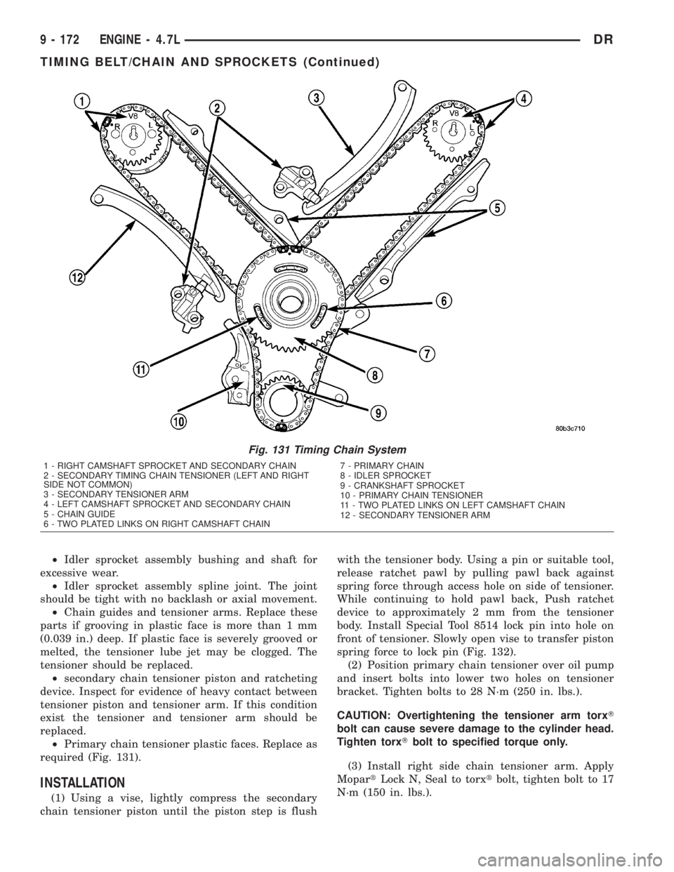
required (Fig. 131).
INSTALLATION
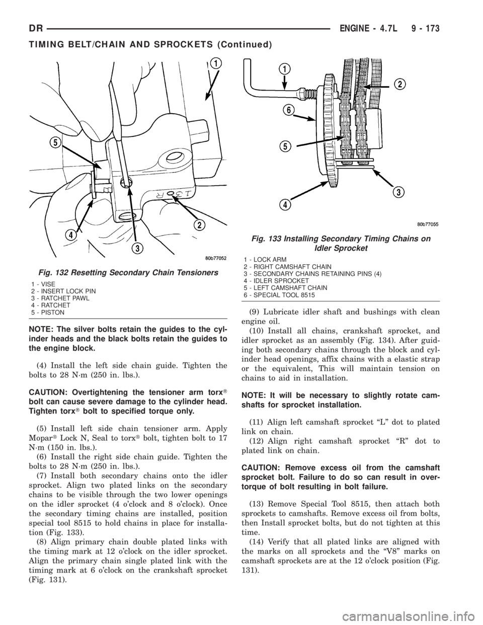
(1) Using a vise, lightly compress the secondary
chain tensioner piston until the piston step is flushwith the tensioner body. Using a pin or suitable tool,
release ratchet pawl by pulling pawl back against
spring force through access hole on side of tensioner.
While continuing to hold pawl back, Push ratchet
device to approximately 2 mm from the tensioner
body. Install Special Tool 8514 lock pin into hole on
front of tensioner. Slowly open vise to transfer piston
spring force to lock pin (Fig. 132).
(2) Position primary chain tensioner over oil pump
and insert bolts into lower two holes on tensioner
bracket. Tighten bolts to 28 N´m (250 in. lbs.).
CAUTION: Overtightening the tensioner arm torxT
bolt can cause severe damage to the cylinder head.
Tighten torxTbolt to specified torque only.
(3) Install right side chain tensioner arm. Apply
MopartLock N, Seal to torxtbolt, tighten bolt to 17
N´m (150 in. lbs.).
Fig. 131 Timing Chain System
1 - RIGHT CAMSHAFT SPROCKET AND SECONDARY CHAIN
2 - SECONDARY TIMING CHAIN TENSIONER (LEFT AND RIGHT
SIDE NOT COMMON)
3 - SECONDARY TENSIONER ARM
4 - LEFT CAMSHAFT SPROCKET AND SECONDARY CHAIN
5 - CHAIN GUIDE
6 - TWO PLATED LINKS ON RIGHT CAMSHAFT CHAIN7 - PRIMARY CHAIN
8 - IDLER SPROCKET
9 - CRANKSHAFT SPROCKET
10 - PRIMARY CHAIN TENSIONER
11 - TWO PLATED LINKS ON LEFT CAMSHAFT CHAIN
12 - SECONDARY TENSIONER ARM
9 - 172 ENGINE - 4.7LDR
TIMING BELT/CHAIN AND SPROCKETS (Continued)
Page 1422 of 2895
NOTE: The silver bolts retain the guides to the cyl-
inder heads and the black bolts retain the guides to
the engine block.
(4) Install the left side chain guide. Tighten the
bolts to 28 N´m (250 in. lbs.).
CAUTION: Overtightening the tensioner arm torxT
bolt can cause severe damage to the cylinder head.
Tighten torxTbolt to specified torque only.
(5) Install left side chain tensioner arm. Apply
MopartLock N, Seal to torxtbolt, tighten bolt to 17
N´m (150 in. lbs.).
(6) Install the right side chain guide. Tighten the
bolts to 28 N´m (250 in. lbs.).
(7) Install both secondary chains onto the idler
sprocket. Align two plated links on the secondary
chains to be visible through the two lower openings
on the idler sprocket (4 o'clock and 8 o'clock). Once
the secondary timing chains are installed, position
special tool 8515 to hold chains in place for installa-
tion (Fig. 133).
(8) Align primary chain double plated links with
the timing mark at 12 o'clock on the idler sprocket.
Align the primary chain single plated link with the
timing mark at 6 o'clock on the crankshaft sprocket
(Fig. 131).(9) Lubricate idler shaft and bushings with clean
engine oil.
(10) Install all chains, crankshaft sprocket, and
idler sprocket as an assembly (Fig. 134). After guid-
ing both secondary chains through the block and cyl-
inder head openings, affix chains with a elastic strap
or the equivalent, This will maintain tension on
chains to aid in installation.
NOTE: It will be necessary to slightly rotate cam-
shafts for sprocket installation.
(11) Align left camshaft sprocket ªLº dot to plated
link on chain.
(12) Align right camshaft sprocket ªRº dot to
plated link on chain.
CAUTION: Remove excess oil from the camshaft
sprocket bolt. Failure to do so can result in over-
torque of bolt resulting in bolt failure.
(13) Remove Special Tool 8515, then attach both
sprockets to camshafts. Remove excess oil from bolts,
then Install sprocket bolts, but do not tighten at this
time.
(14) Verify that all plated links are aligned with
the marks on all sprockets and the ªV8º marks on
camshaft sprockets are at the 12 o'clock position (Fig.
131).
Fig. 132 Resetting Secondary Chain Tensioners
1 - VISE
2 - INSERT LOCK PIN
3 - RATCHET PAWL
4 - RATCHET
5 - PISTON
Fig. 133 Installing Secondary Timing Chains on
Idler Sprocket
1 - LOCK ARM
2 - RIGHT CAMSHAFT CHAIN
3 - SECONDARY CHAINS RETAINING PINS (4)
4 - IDLER SPROCKET
5 - LEFT CAMSHAFT CHAIN
6 - SPECIAL TOOL 8515
DRENGINE - 4.7L 9 - 173
TIMING BELT/CHAIN AND SPROCKETS (Continued)
Page 1472 of 2895
ENGINE - 5.9L
TABLE OF CONTENTS
page page
ENGINE - 5.9L
DESCRIPTION........................224
DIAGNOSIS AND TESTING
DIAGNOSIS AND TESTING - ENGINE
DIAGNOSIS - INTRODUCTION..........225
DIAGNOSIS AND TESTINGÐENGINE
DIAGNOSIS - PERFORMANCE..........226
DIAGNOSIS AND TESTING - ENGINE
DIAGNOSIS - MECHANICAL............228
DIAGNOSIS AND TESTINGÐENGINE
DIAGNOSIS - LUBRICATION............230
DIAGNOSIS AND TESTINGÐCYLINDER
COMPRESSION PRESSURE............231
DIAGNOSIS AND TESTING - CYLINDER
COMBUSTION PRESSURE LEAKAGE.....231
STANDARD PROCEDURE
STANDARD PROCEDURE - FORM-IN-
PLACE GASKETS AND SEALERS........232
STANDARD PROCEDURE - REPAIR
DAMAGED OR WORN THREADS........232
STANDARD PROCEDUREÐHYDROSTATIC
LOCK..............................232
STANDARD PROCEDURE - CYLINDER
BORE HONING......................233
REMOVAL............................233
INSTALLATION........................234
SPECIFICATIONS
5.9L ENGINE........................235
TORQUE...........................239
SPECIAL TOOLS
5.9L ENGINE........................240
AIR CLEANER ELEMENT
REMOVAL............................242
INSTALLATION........................242
CYLINDER HEAD
DESCRIPTION
DESCRIPTIONÐCYLINDER HEAD.......243
DESCRIPTION - CYLINDER HEAD COVER
GASKET...........................243
OPERATION
OPERATIONÐCYLINDER HEAD.........243
OPERATION - CYLINDER HEAD COVER
GASKET...........................243
DIAGNOSIS AND TESTINGÐCYLINDER HEAD
GASKET FAILURE....................243
REMOVAL............................244
CLEANING...........................244
INSPECTION.........................244
INSTALLATION........................244CYLINDER HEAD COVER(S)
REMOVAL............................245
CLEANING...........................245
INSPECTION.........................245
INSTALLATION........................245
INTAKE/EXHAUST VALVES & SEATS
DESCRIPTION........................246
STANDARD PROCEDUREÐVALVES, GUIDES
AND SPRINGS.......................246
REMOVAL............................248
CLEANING...........................248
INSPECTION.........................248
INSTALLATION........................248
ROCKER ARM / ADJUSTER ASSEMBLY
REMOVAL............................249
INSTALLATION........................249
ENGINE BLOCK
CLEANING...........................249
INSPECTION.........................249
CAMSHAFT & BEARINGS (IN BLOCK)
REMOVALÐCAMSHAFT.................250
INSTALLATIONÐCAMSHAFT.............250
CONNECTING ROD BEARINGS
STANDARD PROCEDURE - CONNECTING
ROD BEARING FITTING...............251
CRANKSHAFT
DESCRIPTION........................252
OPERATION..........................252
REMOVAL............................252
INSTALLATION........................252
CRANKSHAFT MAIN BEARINGS
DESCRIPTION........................253
OPERATION..........................253
STANDARD PROCEDUREÐCRANKSHAFT
MAIN BEARING FITTING...............253
REMOVAL............................254
INSTALLATION........................254
CRANKSHAFT OIL SEAL - FRONT
DESCRIPTION........................254
OPERATION..........................254
REMOVAL............................254
INSTALLATION........................255
CRANKSHAFT OIL SEAL - REAR
DESCRIPTION........................255
OPERATION..........................255
REMOVAL............................255
INSTALLATION........................256
DISTRIBUTOR BUSHING
REMOVAL............................258
INSTALLATION........................258
DRENGINE - 5.9L 9 - 223
Page 1485 of 2895
DESCRIPTION SPECIFICATION
Bearing Journal Diameter
No. 1 50.723 ± 50.775 mm
(1.997 ± 1.999 in.)
No. 2 50.317 ± 50.368 mm
(1.981 ± 1.983 in.)
No. 3 49.936 ± 49.987 mm
(1.966 ± 1.968 in.)
No. 4 49.53 ± 49.581 mm
(1.950 ± 1.952 in.)
No. 5 39.611 ± 39.662 mm
(1.5595 ± 1.5615 in.)
Bearing to Journal
Clearance
Standard 0.0254 ± 0.0762 mm
(0.001 ± 0.003 in.)
Service Limit 0.127 mm (0.005 in.)
Camshaft End Play 0.051 ± 0.254 mm
(0.002 ± 0.010 in.)
CONNECTING RODS
Piston Pin bore Diameter 24.966 ± 24.978 mm
(0.9829 ± 0.9834 in.)
Side Clearance 0.152 ± 0.356 mm
(0.006 ± 0.014 in.)
CRANKSHAFT
Rod Journal
Diameter 53.950 ± 53.975 mm
(2.124 ± 2.125 in.)
Out of Round (Max.) 0.0254 mm (0.001 in.)
Taper (Max.) 0.0254 mm (0.001 in.)
Bearing Clearance 0.013 ± 0.056 mm
(0.0005 ± 0.0022 in.)
Main Bearing Journal
Diameter 71.361 ± 71.387 mm
(2.8095 ± 2.8105 in.)
Out of Round (Max.) 0.127 mm (0.001 in.)
Taper (Max.) 0.0254 mm (0.001 in.)
Bearing Clearance
Journal #1 0.013 ± 0.038 mmDESCRIPTION SPECIFICATION
(0.0005 ± 0.0015 in.)
Journals#2-50.013 ± 0.051 mm
(0.0005 ± 0.002 in.)
Service Limit
Journal #1 0.0381 mm (0.0015 in.)
Journals #2-5 0.064 mm (0.0025 in.)
Crankshaft End Play 0.051 ± 0.178 mm
(0.002 ± 0.007 in.)
Service Limit 0.254 mm (0.010 in.)
CYLINDER BLOCK
Cylinder Bore
Diameter 101.60 ± 101.65 mm
(4.000 ± 4.002 in.)
Out of Round (Max.) 0.0254 mm (0.001 in.)
Taper (Max.) 0.0254 mm (0.001 in.)
Lifter Bore
Diameter 22.99 ± 23.01 mm
(0.9051 ± 0.9059 in.)
Distributor Drive Bushing
Press Fit
Bushing to Bore
Interference0.0127 ± 0.3556 mm
(0.0005 ± 0.0140 in.)
Shaft to Bushing
Clearance0.0178 ± 0.0686 mm
(0.0007 ± 0.0027 in.)
CYLINDER HEAD AND VALVES
Valve Seat
Angle 44.25É ± 44.75É
Runout (Max.) 0.0762 mm (0.003 in.)
Width (Finish)
Intake 1.016 ± 1.524 mm
(0.040 ± 0.060 in.)
Exhaust 1.524 ± 2.032 mm
(0.060 ± 0.080 in.)
Valves
Face Angle 43.25É ± 43.75É
Head Diameter
9 - 236 ENGINE - 5.9LDR
ENGINE - 5.9L (Continued)
Page 1490 of 2895
Front Oil Seal Installer 6635
Cam Bearing Remover/Installer C3132±A
Camshaft Holder C-3509
Distributor Bushing Puller C-3052
Distributor Bushing Driver/Burnisher C-3053
Piston Ring Compressor C-385
Crankshaft Main Bearing Remover C-3059
Cylinder Bore Gauge C-119
Pressure Tester Kit 7700
Bloc±Check±Kit C-3685±A
ENGINE SUPPORT FIXTURE 8534
DRENGINE - 5.9L 9 - 241
ENGINE - 5.9L (Continued)
Page 1507 of 2895
DISTRIBUTOR BUSHING
REMOVAL
(1) Remove distributor (Refer to 8 - ELECTRICAL/
IGNITION CONTROL/DISTRIBUTOR - REMOVAL).
(2) Remove the intake manifold (Refer to 9 -
ENGINE/MANIFOLDS/INTAKE MANIFOLD -
REMOVAL).
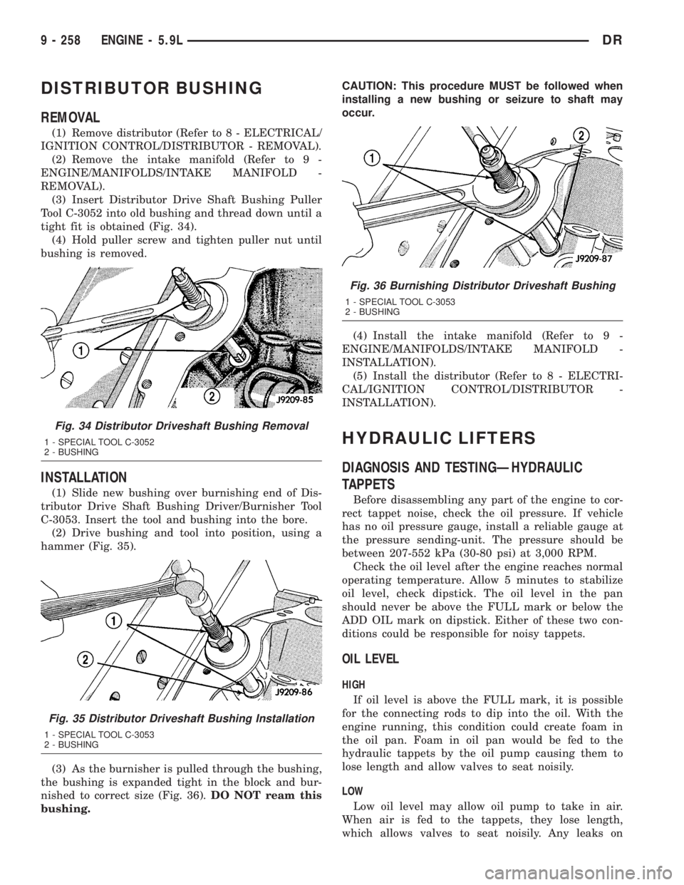
(3) Insert Distributor Drive Shaft Bushing Puller
Tool C-3052 into old bushing and thread down until a
tight fit is obtained (Fig. 34).
(4) Hold puller screw and tighten puller nut until
bushing is removed.
INSTALLATION
(1) Slide new bushing over burnishing end of Dis-
tributor Drive Shaft Bushing Driver/Burnisher Tool
C-3053. Insert the tool and bushing into the bore.
(2) Drive bushing and tool into position, using a
hammer (Fig. 35).
(3) As the burnisher is pulled through the bushing,
the bushing is expanded tight in the block and bur-
nished to correct size (Fig. 36).DO NOT ream this
bushing.CAUTION: This procedure MUST be followed when
installing a new bushing or seizure to shaft may
occur.
(4) Install the intake manifold (Refer to 9 -
ENGINE/MANIFOLDS/INTAKE MANIFOLD -
INSTALLATION).
(5) Install the distributor (Refer to 8 - ELECTRI-
CAL/IGNITION CONTROL/DISTRIBUTOR -
INSTALLATION).
HYDRAULIC LIFTERS
DIAGNOSIS AND TESTINGÐHYDRAULIC
TAPPETS
Before disassembling any part of the engine to cor-
rect tappet noise, check the oil pressure. If vehicle
has no oil pressure gauge, install a reliable gauge at
the pressure sending-unit. The pressure should be
between 207-552 kPa (30-80 psi) at 3,000 RPM.
Check the oil level after the engine reaches normal
operating temperature. Allow 5 minutes to stabilize
oil level, check dipstick. The oil level in the pan
should never be above the FULL mark or below the
ADD OIL mark on dipstick. Either of these two con-
ditions could be responsible for noisy tappets.
OIL LEVEL
HIGH
If oil level is above the FULL mark, it is possible
for the connecting rods to dip into the oil. With the
engine running, this condition could create foam in
the oil pan. Foam in oil pan would be fed to the
hydraulic tappets by the oil pump causing them to
lose length and allow valves to seat noisily.
LOW
Low oil level may allow oil pump to take in air.
When air is fed to the tappets, they lose length,
which allows valves to seat noisily. Any leaks on
Fig. 34 Distributor Driveshaft Bushing Removal
1 - SPECIAL TOOL C-3052
2 - BUSHING
Fig. 35 Distributor Driveshaft Bushing Installation
1 - SPECIAL TOOL C-3053
2 - BUSHING
Fig. 36 Burnishing Distributor Driveshaft Bushing
1 - SPECIAL TOOL C-3053
2 - BUSHING
9 - 258 ENGINE - 5.9LDR
Page 1564 of 2895
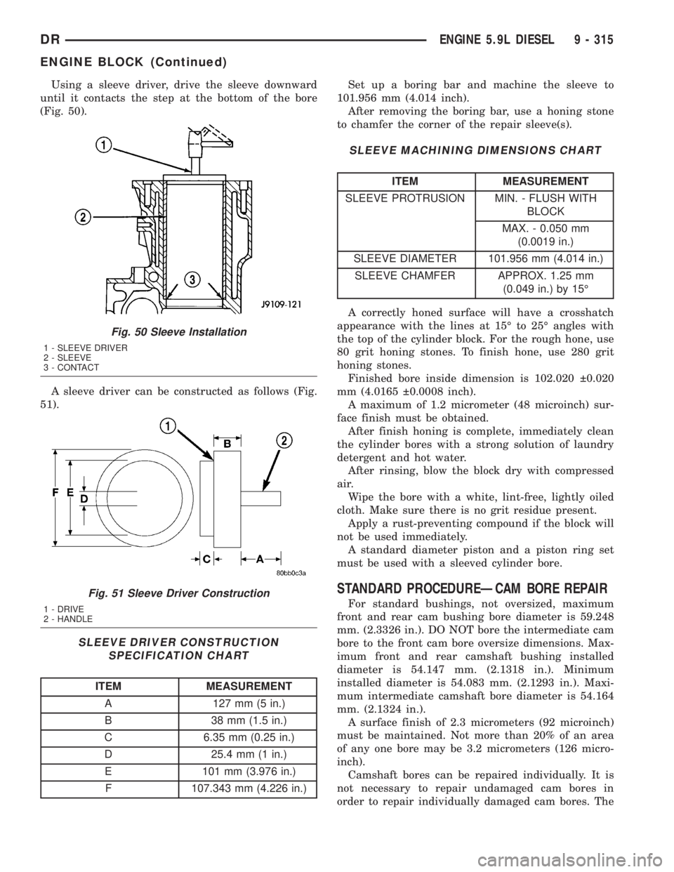
Using a sleeve driver, drive the sleeve downward
until it contacts the step at the bottom of the bore
(Fig. 50).
A sleeve driver can be constructed as follows (Fig.
51).
SLEEVE DRIVER CONSTRUCTION
SPECIFICATION CHART
ITEM MEASUREMENT
A 127 mm (5 in.)
B 38 mm (1.5 in.)
C 6.35 mm (0.25 in.)
D 25.4 mm (1 in.)
E 101 mm (3.976 in.)
F 107.343 mm (4.226 in.)Set up a boring bar and machine the sleeve to
101.956 mm (4.014 inch).
After removing the boring bar, use a honing stone
to chamfer the corner of the repair sleeve(s).
SLEEVE MACHINING DIMENSIONS CHART
ITEM MEASUREMENT
SLEEVE PROTRUSION MIN. - FLUSH WITH
BLOCK
MAX. - 0.050 mm
(0.0019 in.)
SLEEVE DIAMETER 101.956 mm (4.014 in.)
SLEEVE CHAMFER APPROX. 1.25 mm
(0.049 in.) by 15É
A correctly honed surface will have a crosshatch
appearance with the lines at 15É to 25É angles with
the top of the cylinder block. For the rough hone, use
80 grit honing stones. To finish hone, use 280 grit
honing stones.
Finished bore inside dimension is 102.020 0.020
mm (4.0165 0.0008 inch).
A maximum of 1.2 micrometer (48 microinch) sur-
face finish must be obtained.
After finish honing is complete, immediately clean
the cylinder bores with a strong solution of laundry
detergent and hot water.
After rinsing, blow the block dry with compressed
air.
Wipe the bore with a white, lint-free, lightly oiled
cloth. Make sure there is no grit residue present.
Apply a rust-preventing compound if the block will
not be used immediately.
A standard diameter piston and a piston ring set
must be used with a sleeved cylinder bore.
STANDARD PROCEDUREÐCAM BORE REPAIR
For standard bushings, not oversized, maximum
front and rear cam bushing bore diameter is 59.248
mm. (2.3326 in.). DO NOT bore the intermediate cam
bore to the front cam bore oversize dimensions. Max-
imum front and rear camshaft bushing installed
diameter is 54.147 mm. (2.1318 in.). Minimum
installed diameter is 54.083 mm. (2.1293 in.). Maxi-
mum intermediate camshaft bore diameter is 54.164
mm. (2.1324 in.).
A surface finish of 2.3 micrometers (92 microinch)
must be maintained. Not more than 20% of an area
of any one bore may be 3.2 micrometers (126 micro-
inch).
Camshaft bores can be repaired individually. It is
not necessary to repair undamaged cam bores in
order to repair individually damaged cam bores. The
Fig. 50 Sleeve Installation
1 - SLEEVE DRIVER
2 - SLEEVE
3 - CONTACT
Fig. 51 Sleeve Driver Construction
1 - DRIVE
2 - HANDLE
DRENGINE 5.9L DIESEL 9 - 315
ENGINE BLOCK (Continued)