bushing DODGE RAM 2003 Service Workshop Manual
[x] Cancel search | Manufacturer: DODGE, Model Year: 2003, Model line: RAM, Model: DODGE RAM 2003Pages: 2895, PDF Size: 83.15 MB
Page 1828 of 2895
SPECIAL TOOLS
STEERING LINKAGE
DAMPER
REMOVAL
(1) Remove the steering damper mounting nuts
and bolts.
(2) Slide the damper from the isolation bushing.
(3) Remove the damper.
INSTALLATION
(1) Install the steering damper on the axle and iso-
lation bushing. Tighten nut to 95 N´m (75 ft. lbs.).
(2) Install the steering damper on the tie rod.
Tighten nut to 81 N´m (60 ft. lbs.).
DRAG LINK
REMOVAL
(1) Remove the draglink nut from the pitman arm
side.(2) Remove the drag link nut from the knuckle
side.
(3) Remove the drag link from the right knuckle
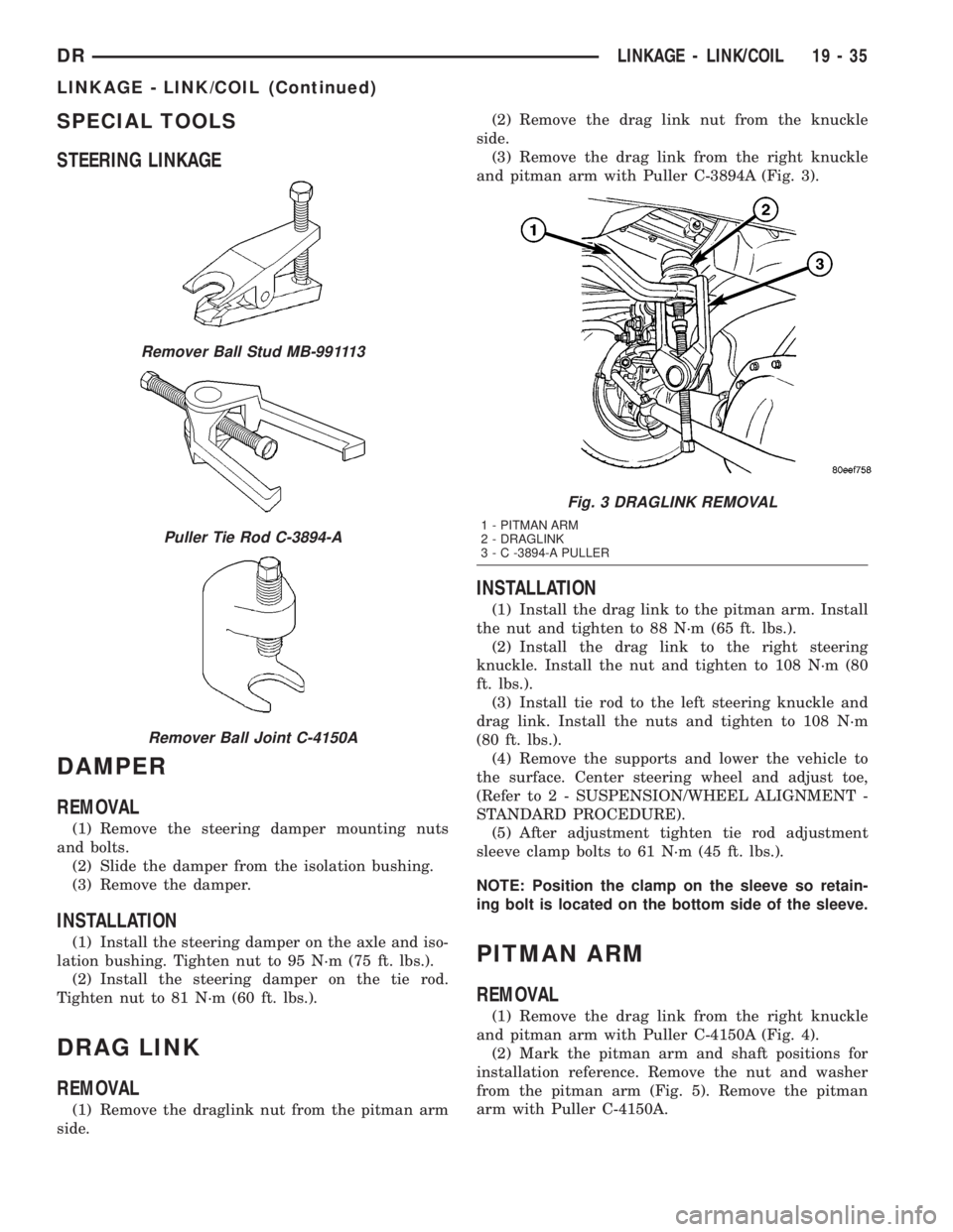
and pitman arm with Puller C-3894A (Fig. 3).
INSTALLATION
(1) Install the drag link to the pitman arm. Install
the nut and tighten to 88 N´m (65 ft. lbs.).
(2) Install the drag link to the right steering
knuckle. Install the nut and tighten to 108 N´m (80
ft. lbs.).
(3) Install tie rod to the left steering knuckle and
drag link. Install the nuts and tighten to 108 N´m
(80 ft. lbs.).
(4) Remove the supports and lower the vehicle to
the surface. Center steering wheel and adjust toe,
(Refer to 2 - SUSPENSION/WHEEL ALIGNMENT -
STANDARD PROCEDURE).
(5) After adjustment tighten tie rod adjustment
sleeve clamp bolts to 61 N´m (45 ft. lbs.).
NOTE: Position the clamp on the sleeve so retain-
ing bolt is located on the bottom side of the sleeve.
PITMAN ARM
REMOVAL
(1) Remove the drag link from the right knuckle
and pitman arm with Puller C-4150A (Fig. 4).
(2) Mark the pitman arm and shaft positions for
installation reference. Remove the nut and washer
from the pitman arm (Fig. 5). Remove the pitman
arm with Puller C-4150A.
Remover Ball Stud MB-991113
Puller Tie Rod C-3894-A
Remover Ball Joint C-4150A
Fig. 3 DRAGLINK REMOVAL
1 - PITMAN ARM
2 - DRAGLINK
3 - C -3894-A PULLER
DRLINKAGE - LINK/COIL 19 - 35
LINKAGE - LINK/COIL (Continued)
Page 1840 of 2895
TRANSMISSION AND TRANSFER CASE
TABLE OF CONTENTS
page page
MANUAL TRANSMISSION - NV3500..........1
MANUAL TRANSMISSION - NV4500..........42
MANUAL TRANSMISSION - NV5600..........87
AUTOMATIC TRANSMISSION - 46RE........129
AUTOMATIC TRANSMISSION - 48RE........310
AUTOMATIC TRANSMISSION - 45RFE/545RFE. . 488
TRANSFER CASE - NV241 GENII...........591
TRANSFER CASE - NV271................623
TRANSFER CASE - NV243................658
TRANSFER CASE - NV273................687
MANUAL TRANSMISSION - NV3500
TABLE OF CONTENTS
page page
MANUAL TRANSMISSION - NV3500
DESCRIPTION..........................1
OPERATION............................1
DIAGNOSIS AND TESTING................3
REMOVAL.............................3
DISASSEMBLY..........................4CLEANING............................15
INSPECTION..........................15
ASSEMBLY............................17
INSTALLATION.........................38
SPECIFICATIONS.......................39
SPECIAL TOOLS.......................40
MANUAL TRANSMISSION -
NV3500
DESCRIPTION
The transmission is a medium-duty 5-speed, con-
stant mesh fully synchronized manual transmission
with fifth gear overdrive range. The transmission is
available in two and four-wheel drive configurations.
The transmission gear case consists of two aluminum
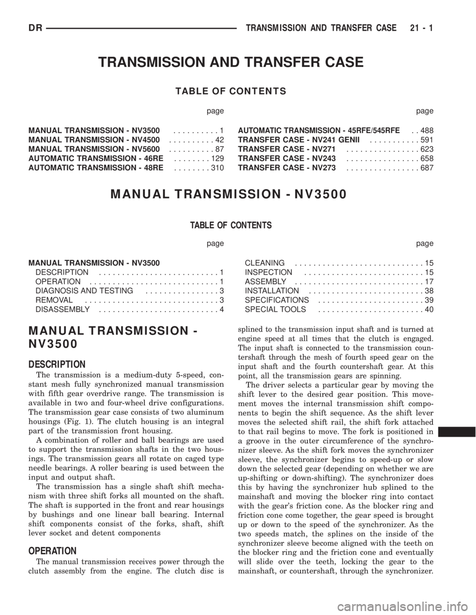
housings (Fig. 1). The clutch housing is an integral
part of the transmission front housing.
A combination of roller and ball bearings are used
to support the transmission shafts in the two hous-
ings. The transmission gears all rotate on caged type
needle bearings. A roller bearing is used between the
input and output shaft.
The transmission has a single shaft shift mecha-
nism with three shift forks all mounted on the shaft.
The shaft is supported in the front and rear housings
by bushings and one linear ball bearing. Internal
shift components consist of the forks, shaft, shift
lever socket and detent components
OPERATION
The manual transmission receives power through the
clutch assembly from the engine. The clutch disc issplined to the transmission input shaft and is turned at
engine speed at all times that the clutch is engaged.
The input shaft is connected to the transmission coun-
tershaft through the mesh of fourth speed gear on the
input shaft and the fourth countershaft gear. At this
point, all the transmission gears are spinning.
The driver selects a particular gear by moving the
shift lever to the desired gear position. This move-
ment moves the internal transmission shift compo-
nents to begin the shift sequence. As the shift lever
moves the selected shift rail, the shift fork attached
to that rail begins to move. The fork is positioned in
a groove in the outer circumference of the synchro-
nizer sleeve. As the shift fork moves the synchronizer
sleeve, the synchronizer begins to speed-up or slow
down the selected gear (depending on whether we are
up-shifting or down-shifting). The synchronizer does
this by having the synchronizer hub splined to the
mainshaft and moving the blocker ring into contact
with the gear's friction cone. As the blocker ring and
friction cone come together, the gear speed is brought
up or down to the speed of the synchronizer. As the
two speeds match, the splines on the inside of the
synchronizer sleeve become aligned with the teeth on
the blocker ring and the friction cone and eventually
will slide over the teeth, locking the gear to the
mainshaft, or countershaft, through the synchronizer.
DRTRANSMISSION AND TRANSFER CASE 21 - 1
Page 1844 of 2895
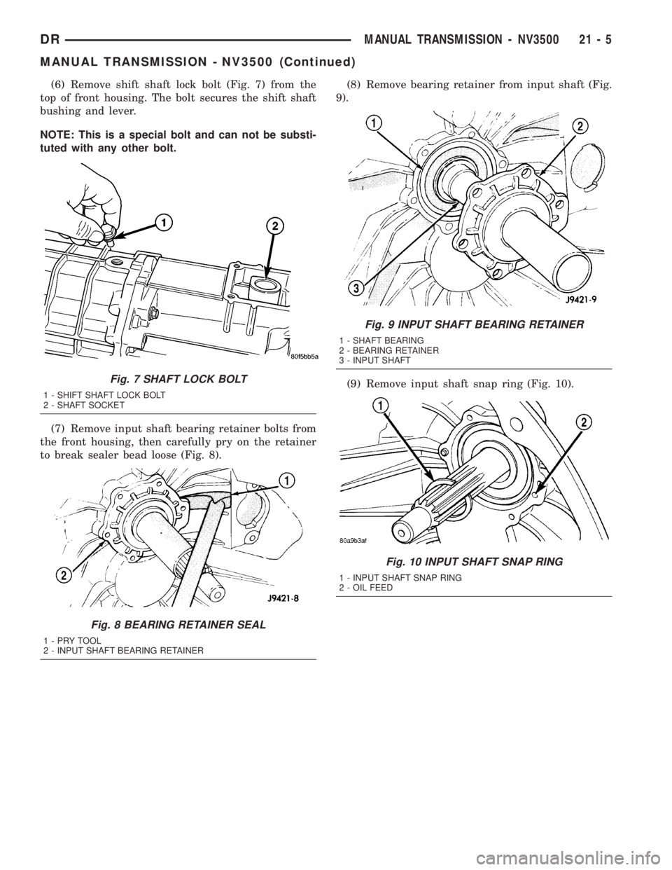
(6) Remove shift shaft lock bolt (Fig. 7) from the
top of front housing. The bolt secures the shift shaft
bushing and lever.
NOTE: This is a special bolt and can not be substi-
tuted with any other bolt.
(7) Remove input shaft bearing retainer bolts from
the front housing, then carefully pry on the retainer
to break sealer bead loose (Fig. 8).(8) Remove bearing retainer from input shaft (Fig.
9).
(9) Remove input shaft snap ring (Fig. 10).
Fig. 7 SHAFT LOCK BOLT
1 - SHIFT SHAFT LOCK BOLT
2 - SHAFT SOCKET
Fig. 8 BEARING RETAINER SEAL
1-PRYTOOL
2 - INPUT SHAFT BEARING RETAINER
Fig. 9 INPUT SHAFT BEARING RETAINER
1 - SHAFT BEARING
2 - BEARING RETAINER
3 - INPUT SHAFT
Fig. 10 INPUT SHAFT SNAP RING
1 - INPUT SHAFT SNAP RING
2 - OIL FEED
DRMANUAL TRANSMISSION - NV3500 21 - 5
MANUAL TRANSMISSION - NV3500 (Continued)
Page 1846 of 2895
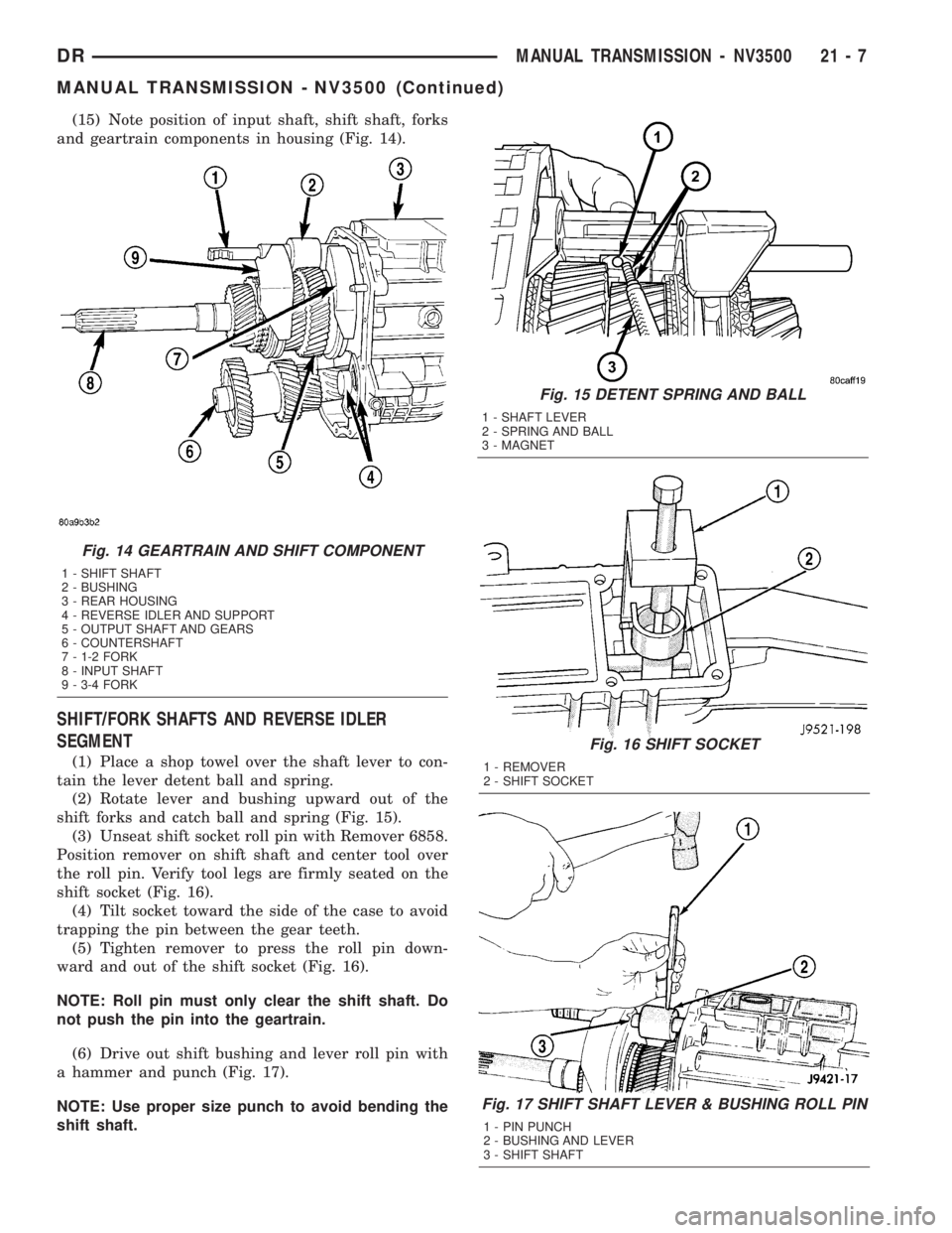
(15) Note position of input shaft, shift shaft, forks
and geartrain components in housing (Fig. 14).
SHIFT/FORK SHAFTS AND REVERSE IDLER
SEGMENT
(1) Place a shop towel over the shaft lever to con-
tain the lever detent ball and spring.
(2) Rotate lever and bushing upward out of the
shift forks and catch ball and spring (Fig. 15).
(3) Unseat shift socket roll pin with Remover 6858.
Position remover on shift shaft and center tool over
the roll pin. Verify tool legs are firmly seated on the
shift socket (Fig. 16).
(4) Tilt socket toward the side of the case to avoid
trapping the pin between the gear teeth.
(5) Tighten remover to press the roll pin down-
ward and out of the shift socket (Fig. 16).
NOTE: Roll pin must only clear the shift shaft. Do
not push the pin into the geartrain.
(6) Drive out shift bushing and lever roll pin with
a hammer and punch (Fig. 17).
NOTE: Use proper size punch to avoid bending the
shift shaft.
Fig. 15 DETENT SPRING AND BALL
1 - SHAFT LEVER
2 - SPRING AND BALL
3 - MAGNET
Fig. 16 SHIFT SOCKET
1 - REMOVER
2 - SHIFT SOCKET
Fig. 17 SHIFT SHAFT LEVER & BUSHING ROLL PIN
1 - PIN PUNCH
2 - BUSHING AND LEVER
3 - SHIFT SHAFT
Fig. 14 GEARTRAIN AND SHIFT COMPONENT
1 - SHIFT SHAFT
2 - BUSHING
3 - REAR HOUSING
4 - REVERSE IDLER AND SUPPORT
5 - OUTPUT SHAFT AND GEARS
6 - COUNTERSHAFT
7 - 1-2 FORK
8 - INPUT SHAFT
9 - 3-4 FORK
DRMANUAL TRANSMISSION - NV3500 21 - 7
MANUAL TRANSMISSION - NV3500 (Continued)
Page 1847 of 2895
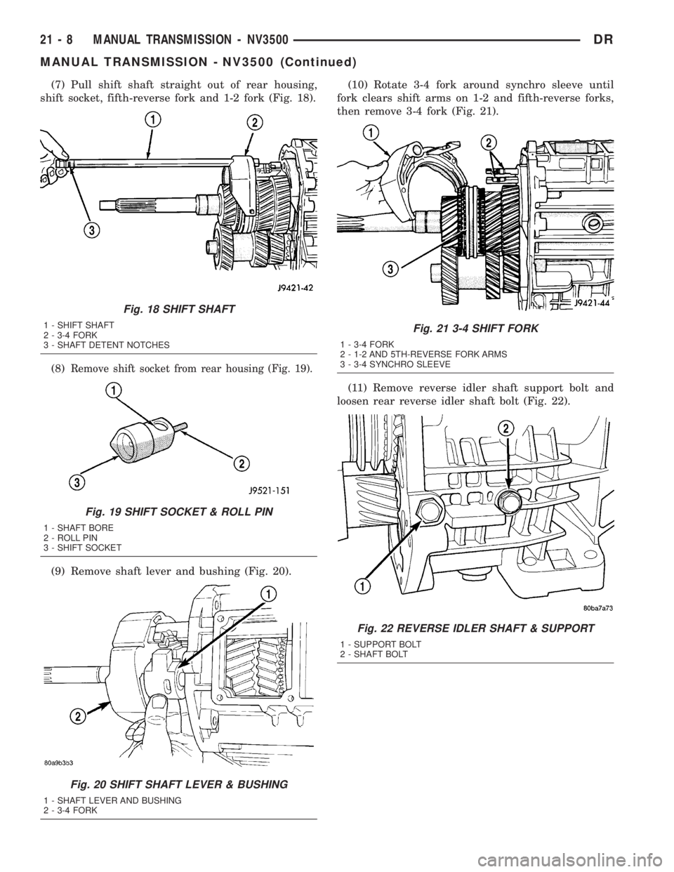
(7) Pull shift shaft straight out of rear housing,
shift socket, fifth-reverse fork and 1-2 fork (Fig. 18).
(8)
Remove shift socket from rear housing (Fig. 19).
(9) Remove shaft lever and bushing (Fig. 20).(10) Rotate 3-4 fork around synchro sleeve until
fork clears shift arms on 1-2 and fifth-reverse forks,
then remove 3-4 fork (Fig. 21).
(11) Remove reverse idler shaft support bolt and
loosen rear reverse idler shaft bolt (Fig. 22).
Fig. 18 SHIFT SHAFT
1 - SHIFT SHAFT
2 - 3-4 FORK
3 - SHAFT DETENT NOTCHES
Fig. 19 SHIFT SOCKET & ROLL PIN
1 - SHAFT BORE
2 - ROLL PIN
3 - SHIFT SOCKET
Fig. 20 SHIFT SHAFT LEVER & BUSHING
1 - SHAFT LEVER AND BUSHING
2 - 3-4 FORK
Fig. 21 3-4 SHIFT FORK
1 - 3-4 FORK
2 - 1-2 AND 5TH-REVERSE FORK ARMS
3 - 3-4 SYNCHRO SLEEVE
Fig. 22 REVERSE IDLER SHAFT & SUPPORT
1 - SUPPORT BOLT
2 - SHAFT BOLT
21 - 8 MANUAL TRANSMISSION - NV3500DR
MANUAL TRANSMISSION - NV3500 (Continued)
Page 1854 of 2895
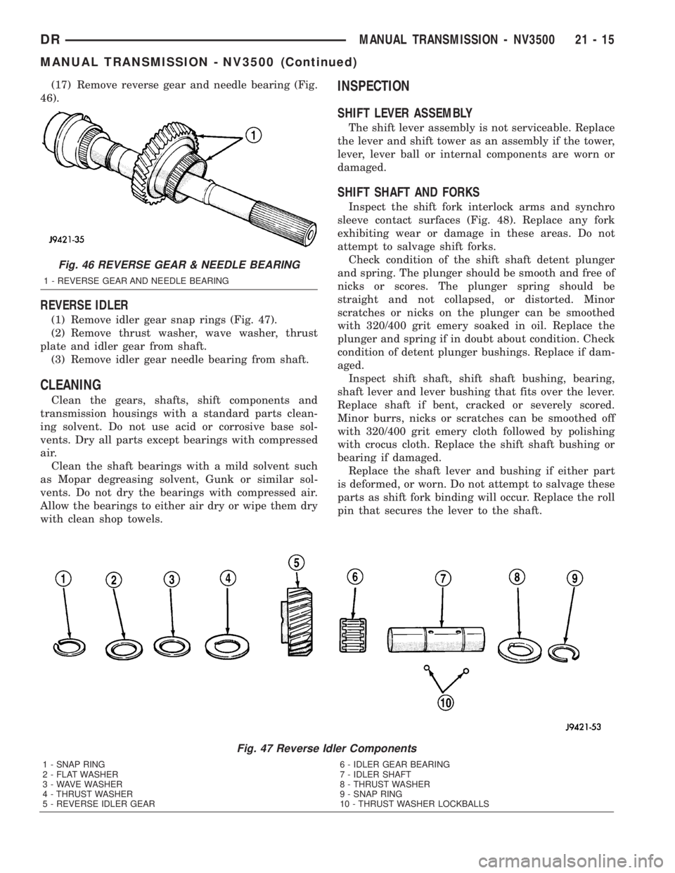
(17) Remove reverse gear and needle bearing (Fig.
46).
REVERSE IDLER
(1) Remove idler gear snap rings (Fig. 47).
(2) Remove thrust washer, wave washer, thrust
plate and idler gear from shaft.
(3) Remove idler gear needle bearing from shaft.
CLEANING
Clean the gears, shafts, shift components and
transmission housings with a standard parts clean-
ing solvent. Do not use acid or corrosive base sol-
vents. Dry all parts except bearings with compressed
air.
Clean the shaft bearings with a mild solvent such
as Mopar degreasing solvent, Gunk or similar sol-
vents. Do not dry the bearings with compressed air.
Allow the bearings to either air dry or wipe them dry
with clean shop towels.
INSPECTION
SHIFT LEVER ASSEMBLY
The shift lever assembly is not serviceable. Replace
the lever and shift tower as an assembly if the tower,
lever, lever ball or internal components are worn or
damaged.
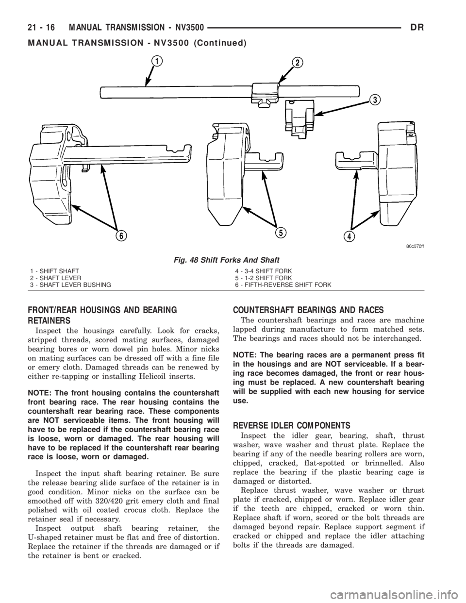
SHIFT SHAFT AND FORKS
Inspect the shift fork interlock arms and synchro
sleeve contact surfaces (Fig. 48). Replace any fork
exhibiting wear or damage in these areas. Do not
attempt to salvage shift forks.
Check condition of the shift shaft detent plunger
and spring. The plunger should be smooth and free of
nicks or scores. The plunger spring should be
straight and not collapsed, or distorted. Minor
scratches or nicks on the plunger can be smoothed
with 320/400 grit emery soaked in oil. Replace the
plunger and spring if in doubt about condition. Check
condition of detent plunger bushings. Replace if dam-
aged.
Inspect shift shaft, shift shaft bushing, bearing,
shaft lever and lever bushing that fits over the lever.
Replace shaft if bent, cracked or severely scored.
Minor burrs, nicks or scratches can be smoothed off
with 320/400 grit emery cloth followed by polishing
with crocus cloth. Replace the shift shaft bushing or
bearing if damaged.
Replace the shaft lever and bushing if either part
is deformed, or worn. Do not attempt to salvage these
parts as shift fork binding will occur. Replace the roll
pin that secures the lever to the shaft.
Fig. 47 Reverse Idler Components
1 - SNAP RING
2 - FLAT WASHER
3 - WAVE WASHER
4 - THRUST WASHER
5 - REVERSE IDLER GEAR6 - IDLER GEAR BEARING
7 - IDLER SHAFT
8 - THRUST WASHER
9 - SNAP RING
10 - THRUST WASHER LOCKBALLS
Fig. 46 REVERSE GEAR & NEEDLE BEARING
1 - REVERSE GEAR AND NEEDLE BEARING
DRMANUAL TRANSMISSION - NV3500 21 - 15
MANUAL TRANSMISSION - NV3500 (Continued)
Page 1855 of 2895
FRONT/REAR HOUSINGS AND BEARING
RETAINERS
Inspect the housings carefully. Look for cracks,
stripped threads, scored mating surfaces, damaged
bearing bores or worn dowel pin holes. Minor nicks
on mating surfaces can be dressed off with a fine file
or emery cloth. Damaged threads can be renewed by
either re-tapping or installing Helicoil inserts.
NOTE: The front housing contains the countershaft
front bearing race. The rear housing contains the
countershaft rear bearing race. These components
are NOT serviceable items. The front housing will
have to be replaced if the countershaft bearing race
is loose, worn or damaged. The rear housing will
have to be replaced if the countershaft rear bearing
race is loose, worn or damaged.
Inspect the input shaft bearing retainer. Be sure
the release bearing slide surface of the retainer is in
good condition. Minor nicks on the surface can be
smoothed off with 320/420 grit emery cloth and final
polished with oil coated crocus cloth. Replace the
retainer seal if necessary.
Inspect output shaft bearing retainer, the
U-shaped retainer must be flat and free of distortion.
Replace the retainer if the threads are damaged or if
the retainer is bent or cracked.
COUNTERSHAFT BEARINGS AND RACES
The countershaft bearings and races are machine
lapped during manufacture to form matched sets.
The bearings and races should not be interchanged.
NOTE: The bearing races are a permanent press fit
in the housings and are NOT serviceable. If a bear-
ing race becomes damaged, the front or rear hous-
ing must be replaced. A new countershaft bearing
will be supplied with each new housing for service
use.
REVERSE IDLER COMPONENTS
Inspect the idler gear, bearing, shaft, thrust
washer, wave washer and thrust plate. Replace the
bearing if any of the needle bearing rollers are worn,
chipped, cracked, flat-spotted or brinnelled. Also
replace the bearing if the plastic bearing cage is
damaged or distorted.
Replace thrust washer, wave washer or thrust
plate if cracked, chipped or worn. Replace idler gear
if the teeth are chipped, cracked or worn thin.
Replace shaft if worn, scored or the bolt threads are
damaged beyond repair. Replace support segment if
cracked or chipped and replace the idler attaching
bolts if the threads are damaged.
Fig. 48 Shift Forks And Shaft
1 - SHIFT SHAFT
2 - SHAFT LEVER
3 - SHAFT LEVER BUSHING4 - 3-4 SHIFT FORK
5 - 1-2 SHIFT FORK
6 - FIFTH-REVERSE SHIFT FORK
21 - 16 MANUAL TRANSMISSION - NV3500DR
MANUAL TRANSMISSION - NV3500 (Continued)
Page 1865 of 2895
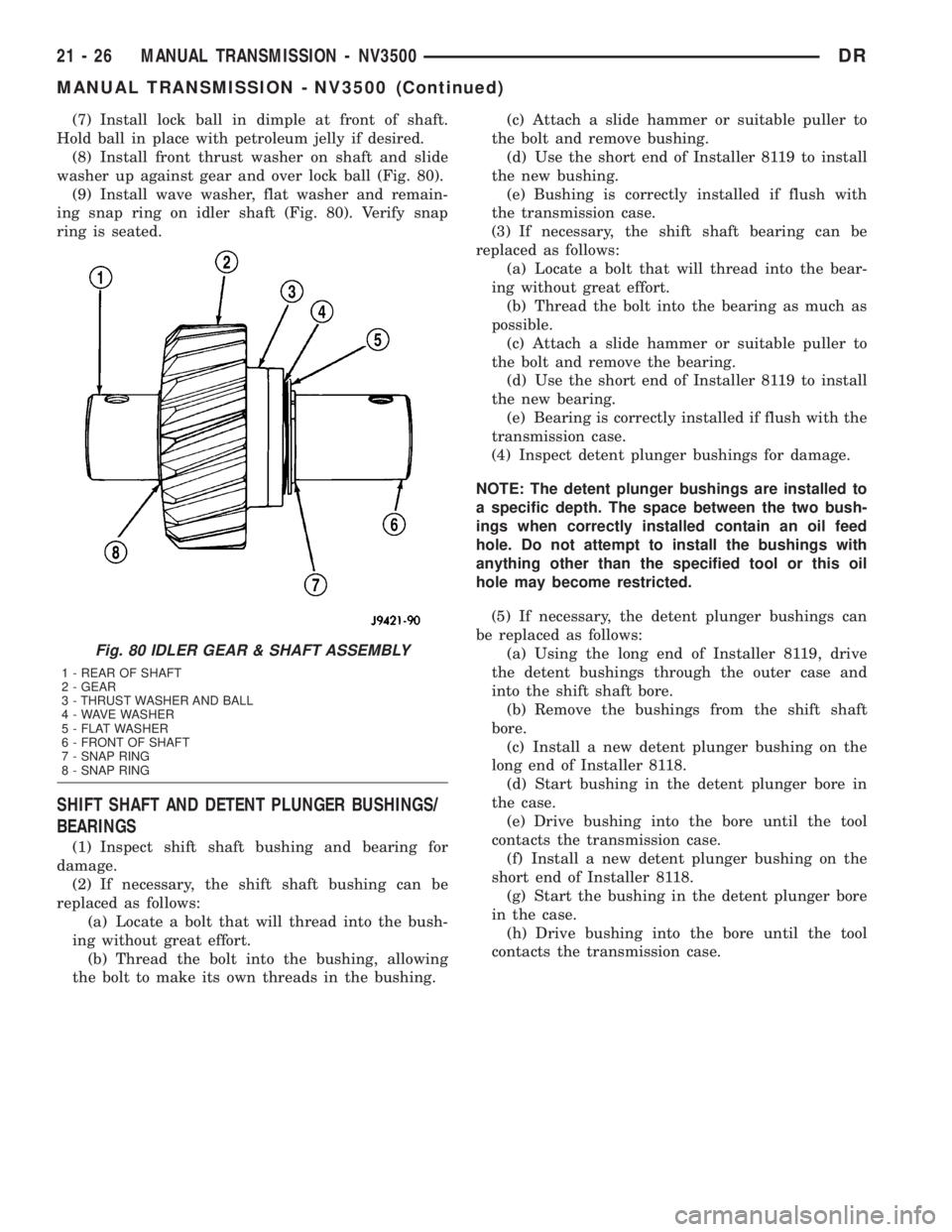
(7) Install lock ball in dimple at front of shaft.
Hold ball in place with petroleum jelly if desired.
(8) Install front thrust washer on shaft and slide
washer up against gear and over lock ball (Fig. 80).
(9) Install wave washer, flat washer and remain-
ing snap ring on idler shaft (Fig. 80). Verify snap
ring is seated.
SHIFT SHAFT AND DETENT PLUNGER BUSHINGS/
BEARINGS
(1) Inspect shift shaft bushing and bearing for
damage.
(2) If necessary, the shift shaft bushing can be
replaced as follows:
(a) Locate a bolt that will thread into the bush-
ing without great effort.
(b) Thread the bolt into the bushing, allowing
the bolt to make its own threads in the bushing.(c) Attach a slide hammer or suitable puller to
the bolt and remove bushing.
(d) Use the short end of Installer 8119 to install
the new bushing.
(e) Bushing is correctly installed if flush with
the transmission case.
(3) If necessary, the shift shaft bearing can be
replaced as follows:
(a) Locate a bolt that will thread into the bear-
ing without great effort.
(b) Thread the bolt into the bearing as much as
possible.
(c) Attach a slide hammer or suitable puller to
the bolt and remove the bearing.
(d) Use the short end of Installer 8119 to install
the new bearing.
(e) Bearing is correctly installed if flush with the
transmission case.
(4) Inspect detent plunger bushings for damage.
NOTE: The detent plunger bushings are installed to
a specific depth. The space between the two bush-
ings when correctly installed contain an oil feed
hole. Do not attempt to install the bushings with
anything other than the specified tool or this oil
hole may become restricted.
(5) If necessary, the detent plunger bushings can
be replaced as follows:
(a) Using the long end of Installer 8119, drive
the detent bushings through the outer case and
into the shift shaft bore.
(b) Remove the bushings from the shift shaft
bore.
(c) Install a new detent plunger bushing on the
long end of Installer 8118.
(d) Start bushing in the detent plunger bore in
the case.
(e) Drive bushing into the bore until the tool
contacts the transmission case.
(f) Install a new detent plunger bushing on the
short end of Installer 8118.
(g) Start the bushing in the detent plunger bore
in the case.
(h) Drive bushing into the bore until the tool
contacts the transmission case.
Fig. 80 IDLER GEAR & SHAFT ASSEMBLY
1 - REAR OF SHAFT
2 - GEAR
3 - THRUST WASHER AND BALL
4 - WAVE WASHER
5 - FLAT WASHER
6 - FRONT OF SHAFT
7 - SNAP RING
8 - SNAP RING
21 - 26 MANUAL TRANSMISSION - NV3500DR
MANUAL TRANSMISSION - NV3500 (Continued)
Page 1869 of 2895
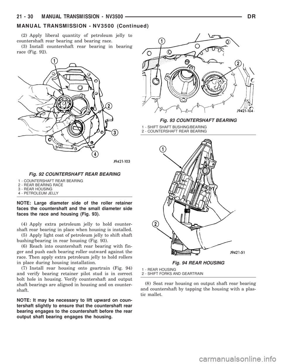
(2) Apply liberal quantity of petroleum jelly to
countershaft rear bearing and bearing race.
(3) Install countershaft rear bearing in bearing
race (Fig. 92).
NOTE: Large diameter side of the roller retainer
faces the countershaft and the small diameter side
faces the race and housing (Fig. 93).
(4) Apply extra petroleum jelly to hold counter-
shaft rear bearing in place when housing is installed.
(5) Apply light coat of petroleum jelly to shift shaft
bushing/bearing in rear housing (Fig. 93).
(6) Reach into countershaft rear bearing with fin-
ger and push each bearing roller outward against the
race. Then apply extra petroleum jelly to hold rollers
in place during housing installation.
(7) Install rear housing onto geartrain (Fig. 94)
and verify bearing retainer pilot stud is in correct
bolt hole in housing. Verify countershaft and output
shaft bearings are aligned in housing and on counter-
shaft.
NOTE: It may be necessary to lift upward on coun-
tershaft slightly to ensure that the countershaft rear
bearing engages to the countershaft before the rear
output shaft bearing engages the housing.(8) Seat rear housing on output shaft rear bearing
and countershaft by tapping the housing with a plas-
tic mallet.
Fig. 92 COUNTERSHAFT REAR BEARING
1 - COUNTERSHAFT REAR BEARING
2 - REAR BEARING RACE
3 - REAR HOUSING
4 - PETROLEUM JELLY
Fig. 93 COUNTERSHAFT BEARING
1 - SHIFT SHAFT BUSHING/BEARING
2 - COUNTERSHAFT REAR BEARING
Fig. 94 REAR HOUSING
1 - REAR HOUSING
2 - SHIFT FORKS AND GEARTRAIN
21 - 30 MANUAL TRANSMISSION - NV3500DR
MANUAL TRANSMISSION - NV3500 (Continued)
Page 1870 of 2895
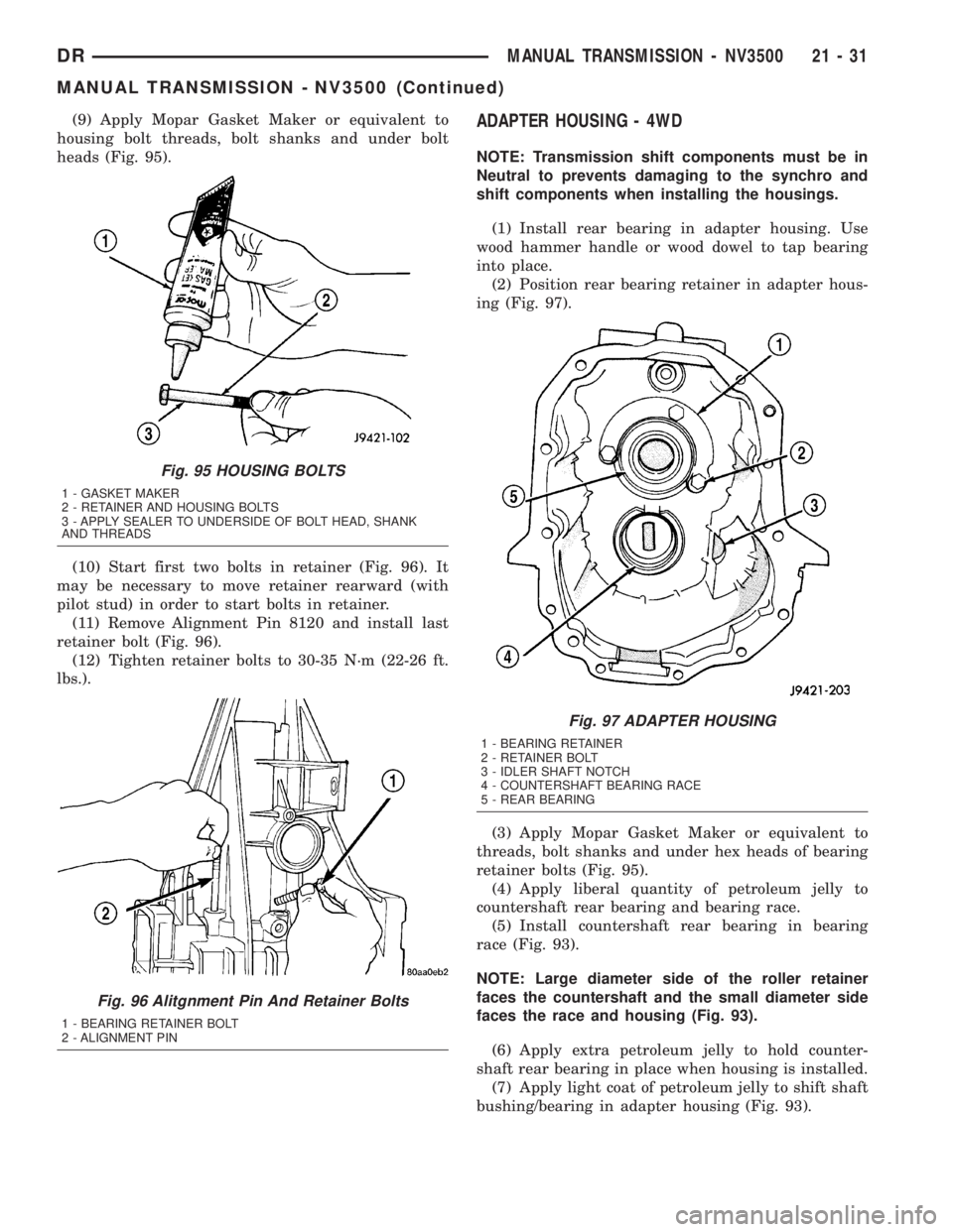
(9) Apply Mopar Gasket Maker or equivalent to
housing bolt threads, bolt shanks and under bolt
heads (Fig. 95).
(10) Start first two bolts in retainer (Fig. 96). It
may be necessary to move retainer rearward (with
pilot stud) in order to start bolts in retainer.
(11) Remove Alignment Pin 8120 and install last
retainer bolt (Fig. 96).
(12) Tighten retainer bolts to 30-35 N´m (22-26 ft.
lbs.).ADAPTER HOUSING - 4WD
NOTE: Transmission shift components must be in
Neutral to prevents damaging to the synchro and
shift components when installing the housings.
(1) Install rear bearing in adapter housing. Use
wood hammer handle or wood dowel to tap bearing
into place.
(2) Position rear bearing retainer in adapter hous-
ing (Fig. 97).
(3) Apply Mopar Gasket Maker or equivalent to
threads, bolt shanks and under hex heads of bearing
retainer bolts (Fig. 95).
(4) Apply liberal quantity of petroleum jelly to
countershaft rear bearing and bearing race.
(5) Install countershaft rear bearing in bearing
race (Fig. 93).
NOTE: Large diameter side of the roller retainer
faces the countershaft and the small diameter side
faces the race and housing (Fig. 93).
(6) Apply extra petroleum jelly to hold counter-
shaft rear bearing in place when housing is installed.
(7) Apply light coat of petroleum jelly to shift shaft
bushing/bearing in adapter housing (Fig. 93).
Fig. 95 HOUSING BOLTS
1 - GASKET MAKER
2 - RETAINER AND HOUSING BOLTS
3 - APPLY SEALER TO UNDERSIDE OF BOLT HEAD, SHANK
AND THREADS
Fig. 96 Alitgnment Pin And Retainer Bolts
1 - BEARING RETAINER BOLT
2 - ALIGNMENT PIN
Fig. 97 ADAPTER HOUSING
1 - BEARING RETAINER
2 - RETAINER BOLT
3 - IDLER SHAFT NOTCH
4 - COUNTERSHAFT BEARING RACE
5 - REAR BEARING
DRMANUAL TRANSMISSION - NV3500 21 - 31
MANUAL TRANSMISSION - NV3500 (Continued)