radiator DODGE RAM SRT-10 2006 Service Repair Manual
[x] Cancel search | Manufacturer: DODGE, Model Year: 2006, Model line: RAM SRT-10, Model: DODGE RAM SRT-10 2006Pages: 5267, PDF Size: 68.7 MB
Page 5050 of 5267
HVAC - SERVICE INFORMATION
DESCRIPTION
A manually controlled single zone type heating-air conditioning system or a manually controlleddualzonetypeheat-
ing-air conditioning system is available on this model.
To maintain the performance level of the heating, ventilation and air conditioning (HVAC) system, the engine cooling
system must be properly maintained. The use of a bug screen is not recommended. Any obstructions in front of the
radiator or A/C condenser will reduce the performance of the A/C and enginecooling systems.
The engine cooling system includes the radiator, thermostat, radiator hoses and the engine coolant pump. Refer to
7 - Cooling for more information before opening or attempting any service to the engine cooling system.
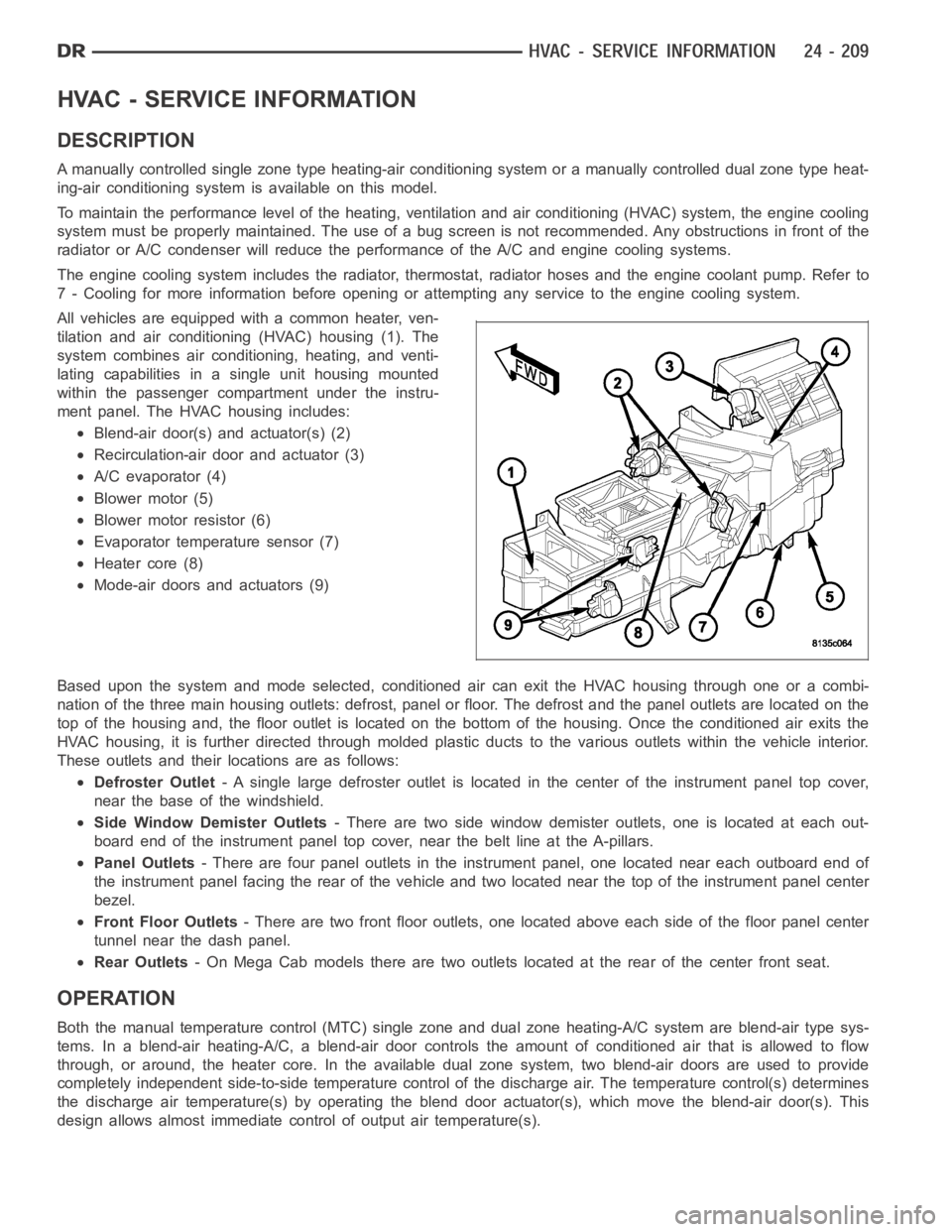
All vehicles are equipped with a common heater, ven-
tilation and air conditioning (HVAC) housing (1). The
system combines air conditioning, heating, and venti-
lating capabilities in a single unit housing mounted
within the passenger compartment under the instru-
ment panel. The HVAC housing includes:
Blend-air door(s) and actuator(s) (2)
Recirculation-air door and actuator (3)
A/C evaporator (4)
Blower motor (5)
Blower motor resistor (6)
Evaporator temperature sensor (7)
Heater core (8)
Mode-air doors and actuators (9)
Based upon the system and mode selected, conditioned air can exit the HVAC housing through one or a combi-
nation of the three main housing outlets: defrost, panel or floor. The defrost and the panel outlets are located on the
top of the housing and, the floor outlet is located on the bottom of the housing. Once the conditioned air exits the
HVAC housing, it is further directed through molded plastic ducts to the various outlets within the vehicle interior.
These outlets and their locations are as follows:
Defroster Outlet- A single large defroster outlet is located in the center of the instrumentpanel top cover,
near the base of the windshield.
Side Window Demister Outlets- There are two side window demister outlets, one is located at each out-
board end of the instrument panel top cover, near the belt line at the A-pillars.
Panel Outlets- There are four panel outlets in the instrument panel, one located near each outboard end of
the instrument panel facing the rear of the vehicle and two located near thetop of the instrument panel center
bezel.
Front Floor Outlets- There are two front floor outlets, one located above each side of the floorpanel center
tunnel near the dash panel.
Rear Outlets- On Mega Cab models there are two outlets located at the rear of the center front seat.
OPERATION
Both the manual temperature control (MTC) single zone and dual zone heating-A/C system are blend-air type sys-
tems. In a blend-air heating-A/C, a blend-air door controls the amount of conditioned air that is allowed to flow
through, or around, the heater core.In the available dual zone system, twoblend-air doors are used to provide
completely independent side-to-side temperature control of the discharge air. The temperature control(s) determines
the discharge air temperature(s) by operating the blend door actuator(s), which move the blend-air door(s). This
design allows almost immediate control of output air temperature(s).
Page 5092 of 5267
TRANSDUCER-A/C PRESSURE
DESCRIPTION
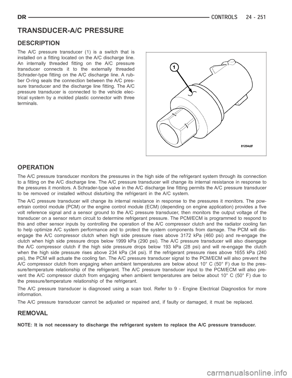
The A/C pressure transducer (1) is a switch that is
installed on a fitting located on the A/C discharge line.
An internally threaded fitting on the A/C pressure
transducer connects it to the externally threaded
Schrader-type fitting on the A/C discharge line. A rub-
ber O-ring seals the connection between the A/C pres-
sure transducer and the discharge line fitting. The A/C
pressure transducer is connected to the vehicle elec-
trical system by a molded plastic connector with three
terminals.
OPERATION
The A/C pressure transducer monitors the pressures in the high side of the refrigerant system through its connection
to a fitting on the A/C discharge line. The A/C pressure transducer will change its internal resistance in response to
the pressures it monitors. A Schrader-type valve in the A/C discharge linefitting permits the A/C pressure transducer
to be removed or installed without disturbing the refrigerant in the A/C system.
The A/C pressure transducer will change its internal resistance in response to the pressures it monitors. The pow-
ertrain control module (PCM) or the engine control module (ECM) (depending on engine application) provides a five
volt reference signal and a sensor ground to the A/C pressure transducer, then monitors the output voltage of the
transducer on a sensor return circuit to determine refrigerant pressure.The PCM/ECM is programmed to respond to
this and other sensor inputs by controlling the operation of the A/C compressor clutch and the radiator cooling fan
to help optimize A/C system performance and to protect the system components from damage. The PCM will dis-
engagetheA/Ccompressorclutchwhenhighsidepressurerisesabove3172kPa (460 psi) and re-engage the
clutch when high side pressure drops below 1999 kPa (290 psi). The A/C pressure transducer will also disengage
the A/C compressor clutch if the high side pressure drops below 193 kPa (28 psi) and will re-engage the clutch
when the high side pressure rises above 234 kPa (34 psi). If the refrigerantpressure rises above 1655 kPa (240
psi), the PCM will actuate the cooling fan. The A/C pressure transducer signal to the PCM/ECM will also prevent the
A/C compressor clutch from engaging when ambient temperatures are below about 10° C (50° F) due to the pres-
sure/temperature relationship of the refrigerant. The A/C pressure transducer input to the PCM/ECM will also pre-
vent the A/C compressor clutch from engaging when ambient temperatures are below about 10° C (50° F) due to
the pressure/temperature relationship of the refrigerant.
The A/C pressure transducer is diagnosed using a scan tool. Refer to 9 - Engine Electrical Diagnostics for more
information.
The A/C pressure transducer cannot be adjusted or repaired and, if faulty or damaged, it must be replaced.
REMOVAL
NOTE: It is not necessary to discharge the refrigerant system to replace the A/C pressure transducer.
Page 5128 of 5267
WARNING: The engine cooling system is designed to develop internal pressures up to 145 kilopascals (21
pounds per square inch). Do not remove or loosen the coolant pressure cap, cylinder block drain plugs,
radiator drain, radiator hoses, heater hoses, or hose clamps while the engine cooling system is hot and
under pressure. Allow the vehicle to cool for a minimum of 15 minutes beforeopening the cooling system
for service. Failure to observe this warning can result in serious burns from the heated engine coolant.
CAUTION
CAUTION: Never add R-12 to a refrigerant system designed to use R-134a. Do not use R-12 equipment or
parts on an R-134a A/C system. These refrigerants are not compatible and damage to the A/C system will
result.
CAUTION: Never use R-12 refrigerant oil in a A/C system designed to use R-134a refrigerant oil. These
refrigerant oils are not compatible and damage to the A/C system will result.
CAUTION: The use of A/C system sealers may result in damage to A/C refrigerant recovery/evacuation/re-
charging equipment and/or A/C system. Many federal, state/provincial and local regulations prohibit the
recharge of A/C systems with known leaks. DaimlerChrysler recommends thedetection of A/C system leaks
through the use of approved leak detectors and fluorescent leak detectiondyes. Vehicles found with A/C
system sealers should be treated as contaminated and replacement of the entire A/C refrigerant system is
recommended. A/C systems found to be contaminated with A/C system sealers, A/C stop-leak products or
seal conditioners voids the warranty for the A/C system.
CAUTION: Recover the refrigerant before opening any fitting or connection. Open the fittings with caution,
even after the system has been discharged. Never open or loosen a connection before recovering the refrig-
erant.
CAUTION: If equipped, do not remove the secondary retention clip from any spring-lock coupler connection
while the refrigerant system is under pressure. Recover the refrigerant before removing the secondary
retention clip. Open the fittings with caution, even after the system has been discharged. Never open or
loosen a connection before recovering the refrigerant.
CAUTION: The internal parts of the A/C system will remain stable as long as moisture-free refrigerant and
refrigerant oil is used. Abnormal amounts of dirt, moisture or air can upset the chemical stability. This may
cause operational troubles or even serious damage if present in more than very small quantities. Before
disconnecting a component, clean the outside of the fittings thoroughly to prevent contamination from
entering the refrigerant system. Keep service tools and the work area clean. Do not open the refrigerant
system or uncap a replacement component until you are ready to service the system. Immediately after
disconnecting a component from the refrigerant system, seal the open fittings with a cap or plug. This will
prevent contamination from entering the A/C system.
CAUTION: Refrigerant oil will absorb moisture from the atmosphere if leftuncapped. Do not open a con-
tainer of refrigerant oil until you are ready to use it. Replace the cap on the oil container immediately after
using. Store refrigerant oil only in a clean, airtight, and moisture-freecontainer.
CAUTION: Do not overcharge the refrigerant system. Overcharging will cause excessive compressor head
pressure and can cause compressor noise and A/C system failure.
Page 5146 of 5267
CONDENSER-A/C
DESCRIPTION
The A/C condenser is located in the front of the engine compartment behind the grille. The A/C condenser is a heat
exchanger that allows the high-pressure refrigerant gas being dischargedbytheA/Ccompressortogiveupitsheat
to the air passing over the condenser fins, which causes the refrigerant tocool and change to a liquid state.
OPERATION
When air passes through the fins of the A/C condenser, the high-pressure refrigerant gas within the A/C condenser
gives up its heat. The refrigerant then condenses as it leaves the A/C condenser and becomes a high-pressure
liquid. The volume of air flowing over the condenser fins is critical to theproper cooling performance of the A/C
system. Therefore, it is important that there are no objects placed in front of the radiator grille openings at the front
of the vehicle or foreign material on the condenser fins that might obstruct proper air flow. Also, any factory-installed
air seals or shrouds must be properly reinstalled following radiator or A/C condenser service.
The A/C condenser cannot be repaired and, if faulty or damaged, it must be replaced.
REMOVAL
3.7L/4.7L/5.7L ENGINES
WARNING: Refer to the applicable warnings and cautions for this system before performing the following
operation (Refer to 24 - HEATING & AIR CONDITIONING/PLUMBING - WARNINGS) and (Refer to 24 - HEAT-
ING & AIR CONDITIONING/PLUMBING - CAUTIONS). Failure to follow the warnings and cautions could result
in possible personal injury or death.
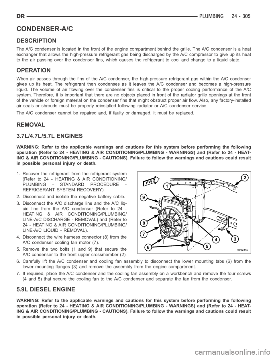
1. Recover the refrigerant from the refrigerant system
(Refer to 24 - HEATING & AIR CONDITIONING/
PLUMBING - STANDARD PROCEDURE -
REFRIGERANT SYSTEM RECOVERY).
2. Disconnect and isolate the negative battery cable.
3. Disconnect the A/C discharge line and the A/C liq-
uidlinefromtheA/Ccondenser(Referto24-
HEATING & AIR CONDITIONING/PLUMBING/
LINE-A/C DISCHARGE - REMOVAL) and (Refer to
24 - HEATING & AIR CONDITIONING/PLUMBING/
LINE-A/C LIQUID - REMOVAL).
4. Disconnect the wire harness connector (8) from the
A/C condenser cooling fan motor (7).
5. Remove the two bolts (1 and 9) that secure the
A/C condenser to the front upper crossmember (2).
6. Carefully lift the A/C condenser and cooling fan assembly to disconnectthe lower mounting tabs (6) from the
lower mounting flanges (3) and remove the assembly from the engine compartment.
7. If required, place the A/C condenser and the cooling fan assembly on a workbench and remove the four screws
(4 and 5) that secure the cooling fan to the A/C condenser and separate the fan from the condenser.
5.9L DIESEL ENGINE
WARNING: Refer to the applicable warnings and cautions for this system before performing the following
operation (Refer to 24 - HEATING & AIR CONDITIONING/PLUMBING - WARNINGS) and (Refer to 24 - HEAT-
ING & AIR CONDITIONING/PLUMBING - CAUTIONS). Failure to follow the warnings and cautions could result
in possible personal injury or death.
Page 5147 of 5267
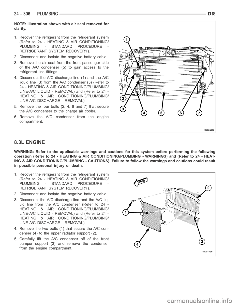
NOTE: Illustration shown with air seal removed for
clarity.
1. Recover the refrigerant from the refrigerant system
(Refer to 24 - HEATING & AIR CONDITIONING/
PLUMBING - STANDARD PROCEDURE -
REFRIGERANT SYSTEM RECOVERY).
2. Disconnect and isolate the negative battery cable.
3. Remove the air seal from the front passenger side
of the A/C condenser (5) to gain access to the
refrigerant line fittings.
4. Disconnect the A/C discharge line (1) and the A/C
liquid line (3) from the A/C condenser (5) (Refer to
24 - HEATING & AIR CONDITIONING/PLUMBING/
LINE-A/C LIQUID - REMOVAL) and (Refer to 24 -
HEATING & AIR CONDITIONING/PLUMBING/
LINE-A/C DISCHARGE - REMOVAL).
5. Remove the four bolts (2, 4, 6 and 7) that secure
the A/C condenser to the charge air cooler.
6. Remove the A/C condenser from the engine
compartment.
8.3L ENGINE
WARNING: Refer to the applicable warnings and cautions for this system before performing the following
operation (Refer to 24 - HEATING & AIR CONDITIONING/PLUMBING - WARNINGS) and (Refer to 24 - HEAT-
ING & AIR CONDITIONING/PLUMBING - CAUTIONS). Failure to follow the warnings and cautions could result
in possible personal injury or death.
1. Recover the refrigerant from the refrigerant system
(Refer to 24 - HEATING & AIR CONDITIONING/
PLUMBING - STANDARD PROCEDURE -
REFRIGERANT SYSTEM RECOVERY).
2. Disconnect and isolate the negative battery cable.
3. Disconnect the A/C discharge line and the A/C liq-
uidlinefromtheA/Ccondenser(Referto24-
HEATING & AIR CONDITIONING/PLUMBING/
LINE-A/C LIQUID - REMOVAL) and (Refer to 24 -
HEATING & AIR CONDITIONING/PLUMBING/
LINE-A/C DISCHARGE - REMOVAL).
4. Remove the two bolts (1) that secure the A/C con-
denser (4) to the upper radiator support (2).
5. Carefully lift the A/C condenser off of the front
bumper support (3) and remove the condenser
from the engine compartment.
Page 5149 of 5267
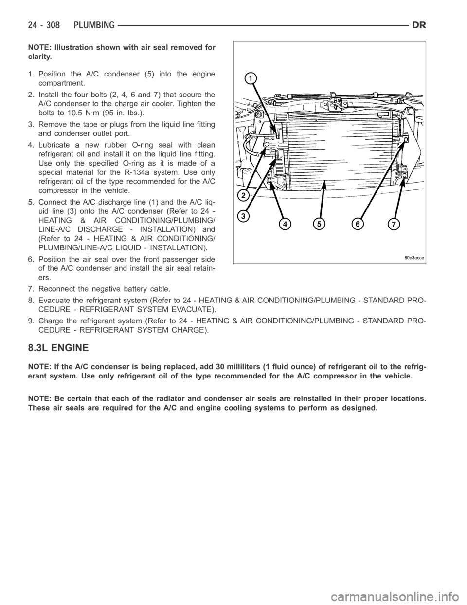
NOTE: Illustration shown with air seal removed for
clarity.
1. Position the A/C condenser (5) into the engine
compartment.
2. Install the four bolts (2, 4, 6 and 7) that secure the
A/C condenser to the charge air cooler. Tighten the
bolts to 10.5 Nꞏm (95 in. lbs.).
3. Remove the tape or plugs from the liquid line fitting
and condenser outlet port.
4. Lubricate a new rubber O-ring seal with clean
refrigerant oil and install it on the liquid line fitting.
UseonlythespecifiedO-ringasitismadeofa
special material for the R-134a system. Use only
refrigerant oil of the type recommended for the A/C
compressor in the vehicle.
5. Connect the A/C discharge line (1) and the A/C liq-
uid line (3) onto the A/C condenser (Refer to 24 -
HEATING & AIR CONDITIONING/PLUMBING/
LINE-A/C DISCHARGE - INSTALLATION) and
(Refer to 24 - HEATING & AIR CONDITIONING/
PLUMBING/LINE-A/C LIQUID - INSTALLATION).
6. Position the air seal over the front passenger side
of the A/C condenser and install the air seal retain-
ers.
7. Reconnect the negative battery cable.
8. Evacuate the refrigerant system (Refer to 24 - HEATING & AIR CONDITIONING/PLUMBING - STANDARD PRO-
CEDURE - REFRIGERANT SYSTEM EVACUATE).
9. Charge the refrigerant system (Refer to 24 - HEATING & AIR CONDITIONING/PLUMBING - STANDARD PRO-
CEDURE - REFRIGERANT SYSTEM CHARGE).
8.3L ENGINE
NOTE: If the A/C condenser is being replaced, add 30 milliliters (1 fluid ounce) of refrigerant oil to the refrig-
erant system. Use only refrigerant oil of the type recommended for the A/C compressor in the vehicle.
NOTE: Be certain that each of the radiator and condenser air seals are reinstalled in their proper locations.
These air seals are required for the A/C and engine cooling systems to perform as designed.
Page 5150 of 5267
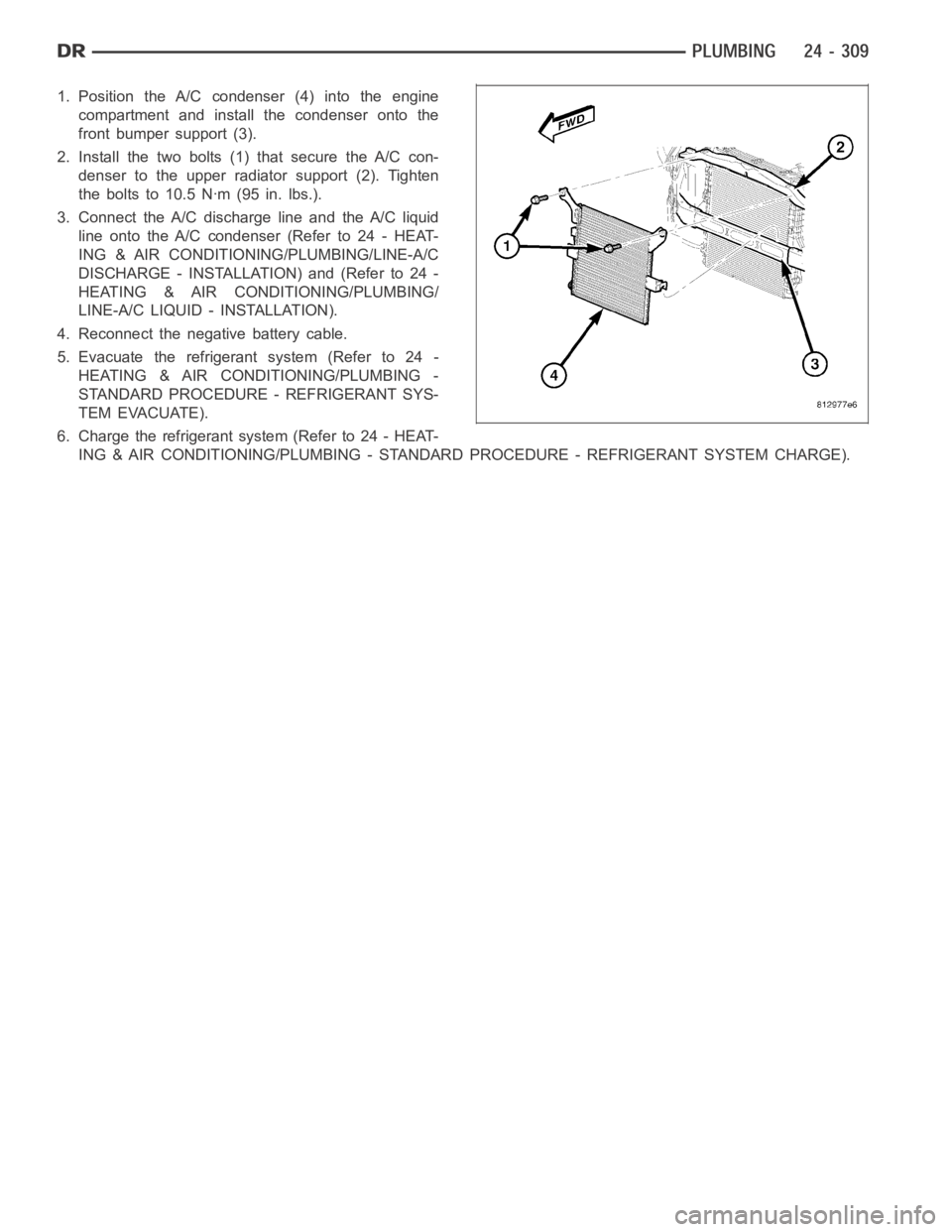
1. Position the A/C condenser (4) into the engine
compartment and install the condenser onto the
front bumper support (3).
2. Install the two bolts (1) that secure the A/C con-
denser to the upper radiator support (2). Tighten
the bolts to 10.5 Nꞏm (95 in. lbs.).
3. Connect the A/C discharge line and the A/C liquid
line onto the A/C condenser(Referto24-HEAT-
ING & AIR CONDITIONING/PLUMBING/LINE-A/C
DISCHARGE - INSTALLATION) and (Refer to 24 -
HEATING & AIR CONDITIONING/PLUMBING/
LINE-A/C LIQUID - INSTALLATION).
4. Reconnect the negative battery cable.
5. Evacuate the refrigerant system (Refer to 24 -
HEATING & AIR CONDITIONING/PLUMBING -
STANDARD PROCEDURE - REFRIGERANT SYS-
TEM EVACUATE).
6. Charge the refrigerant system (Refer to 24 - HEAT-
ING & AIR CONDITIONING/PLUMBING - STANDARD PROCEDURE - REFRIGERANT SYSTEM CHARGE).