radiator DODGE RAM SRT-10 2006 Service Owners Manual
[x] Cancel search | Manufacturer: DODGE, Model Year: 2006, Model line: RAM SRT-10, Model: DODGE RAM SRT-10 2006Pages: 5267, PDF Size: 68.7 MB
Page 3430 of 5267
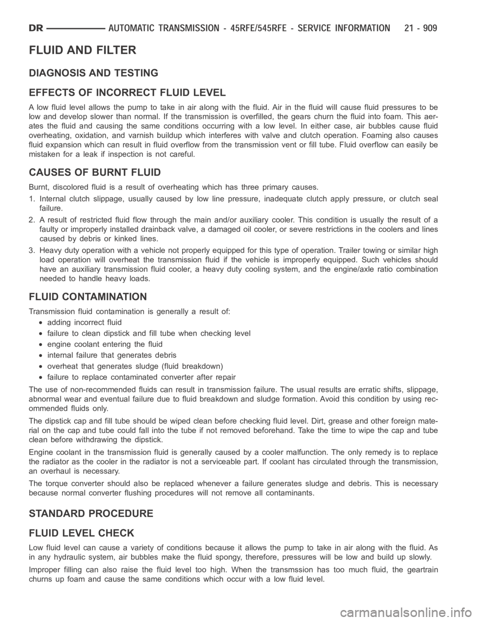
FLUID AND FILTER
DIAGNOSIS AND TESTING
EFFECTS OF INCORRECT FLUID LEVEL
Alowfluidlevelallowsthepumptotakeinairalongwiththefluid.Airinthe fluid will cause fluid pressures to be
low and develop slower than normal. If the transmission is overfilled, thegears churn the fluid into foam. This aer-
ates the fluid and causing the same conditions occurring with a low level. In either case, air bubbles cause fluid
overheating, oxidation, and varnish buildup which interferes with valveand clutch operation. Foaming also causes
fluid expansion which can result in fluid overflow from the transmission vent or fill tube. Fluid overflow can easily be
mistaken for a leak if inspection is not careful.
CAUSES OF BURNT FLUID
Burnt, discolored fluid is a result of overheating which has three primarycauses.
1. Internal clutch slippage, usually caused by low line pressure, inadequate clutch apply pressure, or clutch seal
failure.
2. A result of restricted fluid flow through the main and/or auxiliary cooler. This condition is usually the result of a
faulty or improperly installed drainback valve, a damaged oil cooler, or severe restrictions in the coolers and lines
caused by debris or kinked lines.
3. Heavy duty operation with a vehicle not properly equipped for this type of operation. Trailer towing or similar high
load operation will overheat the transmission fluid if the vehicle is improperly equipped. Such vehicles should
have an auxiliary transmission fluid cooler, a heavy duty cooling system,and the engine/axle ratio combination
needed to handle heavy loads.
FLUID CONTAMINATION
Transmission fluid contamination is generally a result of:
adding incorrect fluid
failure to clean dipstick and fill tube when checking level
engine coolant entering the fluid
internal failure that generates debris
overheat that generates sludge (fluid breakdown)
failure to replace contaminated converter after repair
The use of non-recommended fluids can result in transmission failure. Theusual results are erratic shifts, slippage,
abnormal wear and eventual failure due to fluid breakdown and sludge formation. Avoid this condition by using rec-
ommended fluids only.
The dipstick cap and fill tube should be wiped clean before checking fluid level. Dirt, grease and other foreign mate-
rial on the cap and tube could fall into the tube if not removed beforehand. Take the time to wipe the cap and tube
clean before withdrawing the dipstick.
Engine coolant in the transmission fluid is generally caused by a cooler malfunction. The only remedy is to replace
the radiator as the cooler in the radiator is not a serviceable part. If coolant has circulated through the transmission,
an overhaul is necessary.
The torque converter should also be replaced whenever a failure generatessludge and debris. This is necessary
because normal converter flushing procedures will not remove all contaminants.
STANDARD PROCEDURE
FLUID LEVEL CHECK
Low fluid level can cause a variety of conditions because it allows the pumpto take in air along with the fluid. As
in any hydraulic system, air bubbles make the fluid spongy, therefore, pressures will be low and build up slowly.
Improper filling can also raise the fluid level too high. When the transmssion has too much fluid, the geartrain
churns up foam and cause the same conditions which occur with a low fluid level.
Page 3874 of 5267
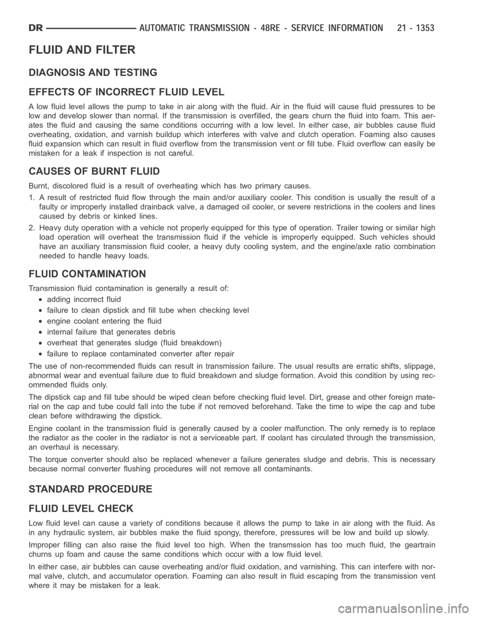
FLUID AND FILTER
DIAGNOSIS AND TESTING
EFFECTS OF INCORRECT FLUID LEVEL
Alowfluidlevelallowsthepumptotakeinairalongwiththefluid.Airinthe fluid will cause fluid pressures to be
low and develop slower than normal. If the transmission is overfilled, thegears churn the fluid into foam. This aer-
ates the fluid and causing the same conditions occurring with a low level. In either case, air bubbles cause fluid
overheating, oxidation, and varnish buildup which interferes with valveand clutch operation. Foaming also causes
fluid expansion which can result in fluid overflow from the transmission vent or fill tube. Fluid overflow can easily be
mistaken for a leak if inspection is not careful.
CAUSES OF BURNT FLUID
Burnt, discolored fluid is a result of overheating which has two primary causes.
1. A result of restricted fluid flow through the main and/or auxiliary cooler. This condition is usually the result of a
faulty or improperly installed drainback valve, a damaged oil cooler, or severe restrictions in the coolers and lines
caused by debris or kinked lines.
2. Heavy duty operation with a vehicle not properly equipped for this type of operation. Trailer towing or similar high
load operation will overheat the transmission fluid if the vehicle is improperly equipped. Such vehicles should
have an auxiliary transmission fluid cooler, a heavy duty cooling system,and the engine/axle ratio combination
needed to handle heavy loads.
FLUID CONTAMINATION
Transmission fluid contamination is generally a result of:
adding incorrect fluid
failure to clean dipstick and fill tube when checking level
engine coolant entering the fluid
internal failure that generates debris
overheat that generates sludge (fluid breakdown)
failure to replace contaminated converter after repair
The use of non-recommended fluids can result in transmission failure. Theusual results are erratic shifts, slippage,
abnormal wear and eventual failure due to fluid breakdown and sludge formation. Avoid this condition by using rec-
ommended fluids only.
The dipstick cap and fill tube should be wiped clean before checking fluid level. Dirt, grease and other foreign mate-
rial on the cap and tube could fall into the tube if not removed beforehand. Take the time to wipe the cap and tube
clean before withdrawing the dipstick.
Engine coolant in the transmission fluid is generally caused by a cooler malfunction. The only remedy is to replace
the radiator as the cooler in the radiator is not a serviceable part. If coolant has circulated through the transmission,
an overhaul is necessary.
The torque converter should also be replaced whenever a failure generatessludge and debris. This is necessary
because normal converter flushing procedures will not remove all contaminants.
STANDARD PROCEDURE
FLUID LEVEL CHECK
Low fluid level can cause a variety of conditions because it allows the pumpto take in air along with the fluid. As
in any hydraulic system, air bubbles make the fluid spongy, therefore, pressures will be low and build up slowly.
Improper filling can also raise the fluid level too high. When the transmssion has too much fluid, the geartrain
churns up foam and cause the same conditions which occur with a low fluid level.
In either case, air bubbles can cause overheating and/or fluid oxidation,and varnishing. This can interfere with nor-
mal valve, clutch, and accumulator operation. Foaming can also result in fluid escaping from the transmission vent
where it may be mistaken for a leak.
Page 3959 of 5267
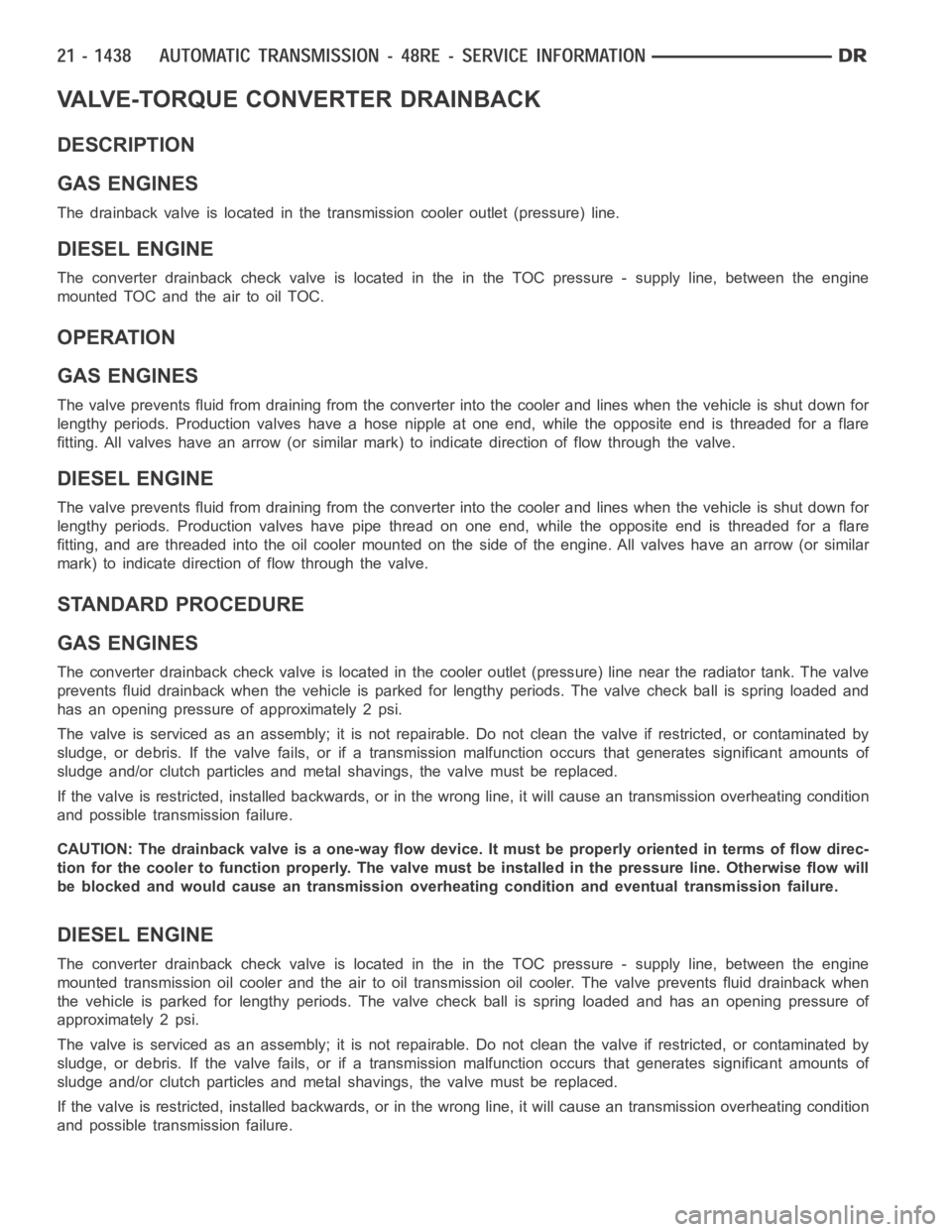
VALVE-TORQUE CONVERTER DRAINBACK
DESCRIPTION
GAS ENGINES
The drainback valve is located in the transmission cooler outlet (pressure) line.
DIESEL ENGINE
The converter drainback check valve is located in the in the TOC pressure - supply line, between the engine
mounted TOC and the air to oil TOC.
OPERATION
GAS ENGINES
The valve prevents fluid from draining from the converter into the cooler and lines when the vehicle is shut down for
lengthy periods. Production valves have a hose nipple at one end, while theopposite end is threaded for a flare
fitting. All valves have an arrow (or similar mark) to indicate direction of flow through the valve.
DIESEL ENGINE
The valve prevents fluid from draining from the converter into the cooler and lines when the vehicle is shut down for
lengthy periods. Production valves have pipe thread on one end, while the opposite end is threaded for a flare
fitting, and are threaded into the oil cooler mounted on the side of the engine. All valves have an arrow (or similar
mark) to indicate direction of flow through the valve.
STANDARD PROCEDURE
GAS ENGINES
The converter drainback check valve is located in the cooler outlet (pressure) line near the radiator tank. The valve
prevents fluid drainback when the vehicle is parked for lengthy periods. The valve check ball is spring loaded and
has an opening pressure of approximately 2 psi.
The valve is serviced as an assembly; it is not repairable. Do not clean the valve if restricted, or contaminated by
sludge, or debris. If the valve fails, or if a transmission malfunction occurs that generates significant amounts of
sludge and/or clutch particles and metal shavings, the valve must be replaced.
If the valve is restricted, installed backwards, or in the wrong line, it will cause an transmission overheating condition
and possible transmission failure.
CAUTION: The drainback valve is a one-way flow device. It must be properly orientedintermsofflowdirec-
tion for the cooler to function properly. The valve must be installed in thepressure line. Otherwise flow will
be blocked and would cause an transmission overheating condition and eventual transmission failure.
DIESEL ENGINE
The converter drainback check valve is located in the in the TOC pressure - supply line, between the engine
mounted transmission oil cooler and the air to oil transmission oil cooler. The valve prevents fluid drainback when
the vehicle is parked for lengthy periods. The valve check ball is spring loaded and has an opening pressure of
approximately 2 psi.
The valve is serviced as an assembly; it is not repairable. Do not clean the valve if restricted, or contaminated by
sludge, or debris. If the valve fails, or if a transmission malfunction occurs that generates significant amounts of
sludge and/or clutch particles and metal shavings, the valve must be replaced.
If the valve is restricted, installed backwards, or in the wrong line, it will cause an transmission overheating condition
and possible transmission failure.
Page 4352 of 5267
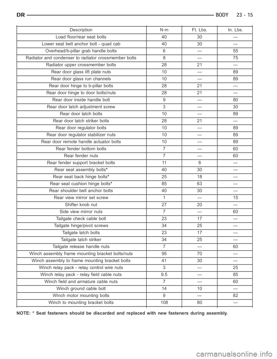
Description Nꞏm Ft. Lbs. In. Lbs.
Load floor/rear seat bolts 40 30 —
Lower seat belt anchor bolt - quad cab 40 30 —
Overhead/b-pillar grab handle bolts 6 — 55
Radiator and condenser to radiator crossmember bolts 8 — 75
Radiator upper crossmember bolts 28 21 —
Rear door glass lift plate nuts 10 — 89
Rear door glass run channels 10 — 89
Rear door hinge to b-pillar bolts 28 21 —
Rear door hinge to door bolts/nuts 28 21 —
Rear door inside handle bolt 9 — 80
Rear door latch adjustment screw 3 — 30
Rear door latch bolts 10 — 89
Rear door latch striker bolts 28 21 —
Rear door regulator bolts 10 — 89
Rear door regulatorstabilizer nuts 10 — 89
Rear door remote handle actuator bolts 10 — 89
Rear fender bottom bolts 7 — 60
Rear fender nuts 7 — 60
Rear fender support bracket bolts 11 8 —
Rear seat assembly bolts*40 30 —
Rear seat back hinge bolts*25 18 —
Rear seat cushion hinge bolts*85 63 —
Rear shoulder belt anchor bolts 40 30 —
Rear view mirror set screw 1 — 15
Shifter knob nut 27 20 —
Side view mirror nuts 7 — 60
Tailgate check cable bolt 23 17 —
Tailgate hinge/pivot screws 34 25 —
Tailgate latch bolts 23 17 —
Tailgate latch striker 34 25 —
Tailgate release handle nuts 7 — 60
Winch assembly frame mounting bracket bolts/nuts 95 70 —
Winch assembly to frame mounting bracket bolts 41 30 —
Winch relay pack - relay control wire nuts 3 — 25
Winch relay pack - relay field cable nuts 9.5 — 85
Winch field and armature cable nuts 7 — 60
Winch ground cable bolt 14 10 —
Winch motor mounting bolts 9 — 82
Winch to mounting bracket bolts 108 80 —
NOTE: * Seat fasteners should be discarded and replaced with new fastenersduring assembly.
Page 4423 of 5267
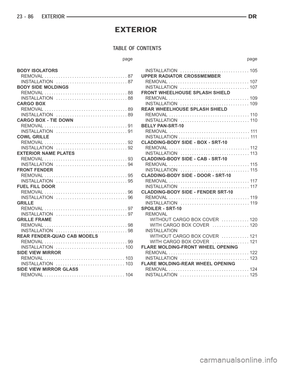
page page
BODY ISOLATORS
REMOVAL .................................... 87
INSTALLATION ............................... 87
BODY SIDE MOLDINGS
REMOVAL .................................... 88
INSTALLATION ............................... 88
CARGO BOX
REMOVAL .................................... 89
INSTALLATION ............................... 89
CARGO BOX - TIE DOWN
REMOVAL .................................... 91
INSTALLATION ............................... 91
COWL GRILLE
REMOVAL .................................... 92
INSTALLATION ............................... 92
EXTERIOR NAME PLATES
REMOVAL .................................... 93
INSTALLATION ............................... 94
FRONT FENDER
REMOVAL .................................... 95
INSTALLATION ............................... 95
FUEL FILL DOOR
REMOVAL .................................... 96
INSTALLATION ............................... 96
GRILLE
REMOVAL .................................... 97
INSTALLATION ............................... 97
GRILLE FRAME
REMOVAL .................................... 98
INSTALLATION ............................... 98
REAR FENDER-QUAD CAB MODELS
REMOVAL .................................... 99
INSTALLATION .............................. 100
SIDE VIEW MIRROR
REMOVAL ................................... 103
INSTALLATION .............................. 103
SIDE VIEW MIRROR GLASS
REMOVAL ................................... 104INSTALLATION .............................. 105
UPPER RADIATOR CROSSMEMBER
REMOVAL ................................... 107
INSTALLATION .............................. 107
FRONT WHEELHOUSE SPLASH SHIELD
REMOVAL ................................... 109
INSTALLATION .............................. 109
REAR WHEELHOUSE SPLASH SHIELD
REMOVAL ................................... 110
INSTALLATION .............................. 110
BELLY PAN-SRT-10
REMOVAL ................................... 111
INSTALLATION ............................... 111
CLADDING-BODY SIDE - BOX - SRT-10
REMOVAL ................................... 112
INSTALLATION .............................. 113
CLADDING-BODY SIDE - CAB - SRT-10
REMOVAL ................................... 115
INSTALLATION .............................. 115
CLADDING-BODY SIDE - DOOR - SRT-10
REMOVAL ................................... 117
INSTALLATION .............................. 117
CLADDING-BODY SIDE - FENDER SRT-10
REMOVAL ................................... 119
INSTALLATION .............................. 119
SPOILER - SRT-10
REMOVAL
WITHOUT CARGO BOX COVER ............ 120
WITH CARGO BOX COVER ................ 120
INSTALLATION
WITHOUT CARGO BOX COVER ............ 121
WITH CARGO BOX COVER ................ 121
FLARE MOLDING-FRONT WHEEL OPENING
REMOVAL ................................... 122
INSTALLATION .............................. 123
FLARE MOLDING-REAR WHEEL OPENING
REMOVAL ................................... 124
INSTALLATION .............................. 125
Page 4444 of 5267
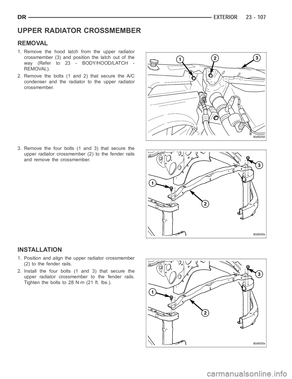
UPPER RADIATOR CROSSMEMBER
REMOVAL
1. Remove the hood latch from the upper radiator
crossmember (3) and position the latch out of the
way(Referto23-BODY/HOOD/LATCH-
REMOVAL).
2. Remove the bolts (1 and 2) that secure the A/C
condenser and the radiator to the upper radiator
crossmember.
3. Remove the four bolts (1 and 3) that secure the
upper radiator crossmember (2) to the fender rails
and remove the crossmember.
INSTALLATION
1. Position and align the upper radiator crossmember
(2) to the fender rails.
2. Install the four bolts (1 and 3) that secure the
upper radiator crossmember to the fender rails.
Tighten the bolts to 28 Nꞏm (21 ft. lbs.).
Page 4445 of 5267
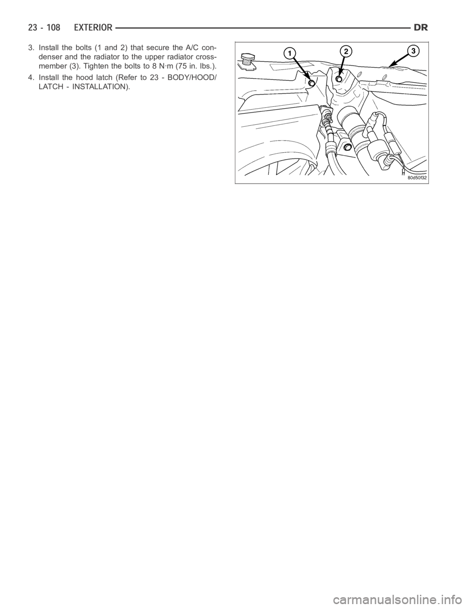
3. Install the bolts (1 and 2) that secure the A/C con-
denser and the radiator to the upper radiator cross-
member (3). Tighten the bolts to 8 Nꞏm (75 in. lbs.).
4. Install the hood latch (Refer to 23 - BODY/HOOD/
LATCH - INSTALLATION).
Page 4470 of 5267
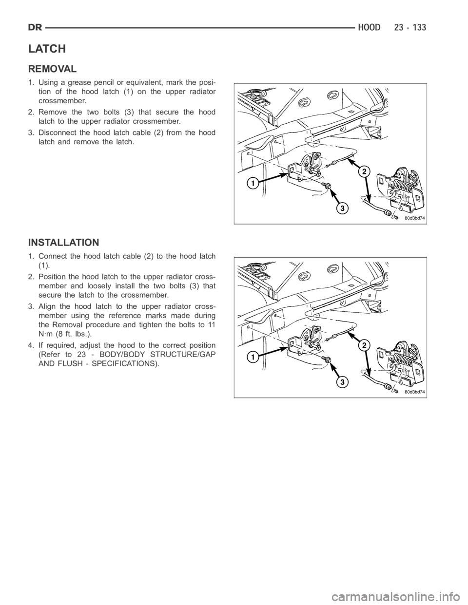
LATCH
REMOVAL
1. Using a grease pencil or equivalent, mark the posi-
tion of the hood latch (1) on the upper radiator
crossmember.
2. Remove the two bolts (3) that secure the hood
latch to the upper radiator crossmember.
3. Disconnect the hood latch cable (2) from the hood
latch and remove the latch.
INSTALLATION
1. Connect the hood latch cable (2) to the hood latch
(1).
2. Position the hood latch to the upper radiator cross-
member and loosely install the two bolts (3) that
secure the latch to the crossmember.
3. Align the hood latch to the upper radiator cross-
member using the reference marks made during
the Removal procedure and tighten the bolts to 11
Nꞏm (8 ft. lbs.).
4. If required, adjust the hood to the correct position
(Refer to 23 - BODY/BODY STRUCTURE/GAP
AND FLUSH - SPECIFICATIONS).
Page 4471 of 5267
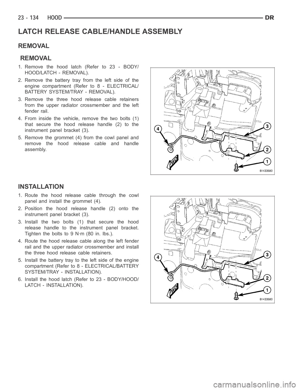
LATCH RELEASE CABLE/HANDLE ASSEMBLY
REMOVAL
REMOVAL
1.Removethehoodlatch(Referto23-BODY/
HOOD/LATCH - REMOVAL).
2. Remove the battery tray from the left side of the
engine compartment (Refer to 8 - ELECTRICAL/
BATTERY SYSTEM/TRAY - REMOVAL).
3. Remove the three hood release cable retainers
from the upper radiator crossmember and the left
fender rail.
4. From inside the vehicle, remove the two bolts (1)
that secure the hood release handle (2) to the
instrument panel bracket (3).
5. Remove the grommet (4) from the cowl panel and
remove the hood release cable and handle
assembly.
INSTALLATION
1. Route the hood release cable through the cowl
panel and install the grommet (4).
2. Position the hood release handle (2) onto the
instrument panel bracket (3).
3. Install the two bolts (1) that secure the hood
release handle to the instrument panel bracket.
Tightentheboltsto9Nꞏm(80in.lbs.).
4. Route the hood release cable along the left fender
rail and the upper radiator crossmember and install
the three hood release cable retainers.
5. Install the battery tray to the left side of the engine
compartment (Refer to 8 - ELECTRICAL/BATTERY
SYSTEM/TRAY - INSTALLATION).
6. Install the hood latch (Refer to 23 - BODY/HOOD/
LATCH - INSTALLATION).
Page 4732 of 5267
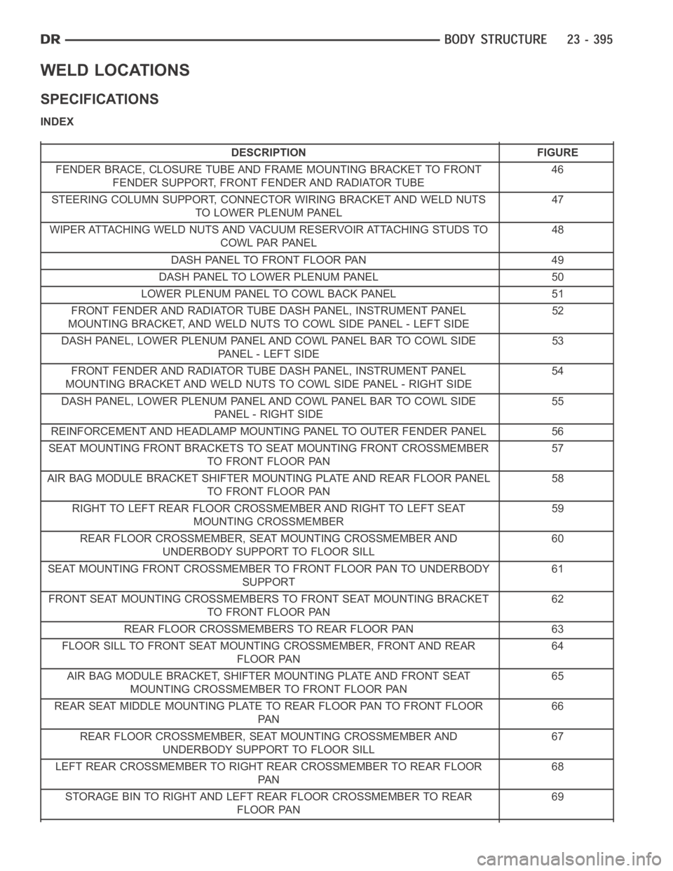
WELD LOCATIONS
SPECIFICATIONS
INDEX
DESCRIPTION FIGURE
FENDER BRACE, CLOSURE TUBE AND FRAME MOUNTING BRACKET TO FRONT
FENDER SUPPORT, FRONT FENDER AND RADIATOR TUBE46
STEERING COLUMN SUPPORT, CONNECTOR WIRING BRACKET AND WELD NUTS
TO LOWER PLENUM PANEL47
WIPER ATTACHING WELD NUTS AND VACUUM RESERVOIR ATTACHING STUDS TO
COWL PAR PANEL48
DASH PANEL TO FRONT FLOOR PAN 49
DASH PANEL TO LOWER PLENUM PANEL 50
LOWER PLENUM PANEL TO COWL BACK PANEL 51
FRONT FENDER AND RADIATOR TUBE DASH PANEL, INSTRUMENT PANEL
MOUNTING BRACKET, AND WELD NUTS TO COWL SIDE PANEL - LEFT SIDE52
DASH PANEL, LOWER PLENUM PANEL AND COWL PANEL BAR TO COWL SIDE
PA N E L - L E F T S I D E53
FRONT FENDER AND RADIATOR TUBE DASH PANEL, INSTRUMENT PANEL
MOUNTING BRACKET AND WELD NUTS TO COWL SIDE PANEL - RIGHT SIDE54
DASH PANEL, LOWER PLENUM PANEL AND COWL PANEL BAR TO COWL SIDE
PANEL - RIGHT SIDE55
REINFORCEMENT AND HEADLAMP MOUNTING PANEL TO OUTER FENDER PANEL 56
SEAT MOUNTING FRONT BRACKETS TO SEAT MOUNTING FRONT CROSSMEMBER
TO FRONT FLOOR PAN57
AIR BAG MODULE BRACKET SHIFTER MOUNTING PLATE AND REAR FLOOR PANEL
TO FRONT FLOOR PAN58
RIGHT TO LEFT REAR FLOOR CROSSMEMBER AND RIGHT TO LEFT SEAT
MOUNTING CROSSMEMBER59
REAR FLOOR CROSSMEMBER, SEAT MOUNTING CROSSMEMBER AND
UNDERBODY SUPPORT TO FLOOR SILL60
SEAT MOUNTING FRONT CROSSMEMBER TO FRONT FLOOR PAN TO UNDERBODY
SUPPORT61
FRONT SEAT MOUNTING CROSSMEMBERS TO FRONT SEAT MOUNTING BRACKET
TO FRONT FLOOR PAN62
REAR FLOOR CROSSMEMBERS TO REAR FLOOR PAN 63
FLOOR SILL TO FRONT SEAT MOUNTING CROSSMEMBER, FRONT AND REAR
FLOOR PAN64
AIR BAG MODULE BRACKET, SHIFTER MOUNTING PLATE AND FRONT SEAT
MOUNTING CROSSMEMBER TO FRONT FLOOR PAN65
REAR SEAT MIDDLE MOUNTING PLATE TO REAR FLOOR PAN TO FRONT FLOOR
PA N66
REAR FLOOR CROSSMEMBER, SEAT MOUNTING CROSSMEMBER AND
UNDERBODY SUPPORT TO FLOOR SILL67
LEFT REAR CROSSMEMBER TO RIGHT REAR CROSSMEMBER TO REAR FLOOR
PA N68
STORAGE BIN TO RIGHT AND LEFT REAR FLOOR CROSSMEMBER TO REAR
FLOOR PAN69