radiator DODGE RAM SRT-10 2006 Service Manual PDF
[x] Cancel search | Manufacturer: DODGE, Model Year: 2006, Model line: RAM SRT-10, Model: DODGE RAM SRT-10 2006Pages: 5267, PDF Size: 68.7 MB
Page 2016 of 5267
CASE - FRONT
REMOVAL
1. Disconnect the battery negative cables.
2. Raise vehicle on hoist.
3. Partially drain engine coolant into container suitable for re-use (Refer to 7 - COOLING - STANDARD PROCE-
DURE).
4. Lower vehicle.
5. Remove radiator upper hose.
6. Disconnect coolant recovery bottle hose from radiator filler neck.
7. Remove viscous fan/drive/shroud assembly (Refer to 7 - COOLING/ENGINE/RADIATOR FAN - REMOVAL).
8. Remove the accessory drive belt (Refer to 7 - COOLING/ACCESSORY DRIVE/DRIVE BELTS - REMOVAL).
9. Remove the cooling fan support/hub from the front of the engine.
10. Raisethevehicleonhoist.
11. Remove the crankshaft damper (Refer to 9 - ENGINE/ENGINE BLOCK/VIBRATION DAMPER - REMOVAL) and
speed indicator ring.
12. Remove the lower fan shroud bracket.
13. Remove the upper fan shroud bracket that is mounted to the gear housing.
14. Lower the vehicle.
15. Remove the power steering pump.
16. Remove the accessory drive belt tensioner.
17. Remove the gear cover-to-housing bolts and gently pry the cover away from the housing, taking care not to mar
the gasket surfaces.
18. Remove the fuel injection pump (Refer to 14 - FUEL SYSTEM/FUEL DELIVERY/FUEL INJECTION PUMP -
REMOVAL).
19. Disconnect the camshaft position sensor connector.
20. Disconnect and remove engine speed sensor.
21. Remove the camshaft (Refer to 9 - ENGINE/ENGINE BLOCK/CAMSHAFT & BEARINGS (IN BLOCK) -
REMOVAL).
22. Remove the six front oil pan fasteners.
23. Remove the gear housing fasteners.
NOTE: Use care when removing the gear housing, to avoid damage to the oil pangasket, as the gasket will
be reused if it is not damaged.
24. Slide a feeler gauge between the gear housing and oil pan gasket, to break the gasket seal.
25. Remove the gear housing and gasket.
26. Clean the gasket material from the cylinder block and gear housing.
Page 2018 of 5267
13. Remove the seal pilot. Install front seal dust shield.
14. Raise the vehicle.
15. Install the crankshaft damper and speed indicator ring (Refer to 9 - ENGINE/ENGINE BLOCK/VIBRATION
DAMPER - INSTALLATION). Torque bolts to 40 Nm (30 ft. lbs.), plus an additional 60°.
16. Install the lower fan shroud bracket. Torque bolts to 24 Nꞏm (18 ft. lbs.) torque.
17. Install the upper fan shroud brackets. Hand tighten only.
18. Lower vehicle.
19. Install the fan support/hub assembly and tighten bolts to 32 Nꞏm (24 ft.lbs.) torque.
20. Install the power steering pump.
21. Install the accessory drive belt tensioner. Torque bolt to 43 Nꞏm (32 ft. lbs.) torque.
22. Install the accessory drive belt (Refer to 7 - COOLING/ACCESSORY DRIVE/DRIVE BELTS - INSTALLATION).
23. Install the upper cooling fan/drive/shroud assembly (Refer to 7 - COOLING/ENGINE/RADIATOR FAN - INSTAL-
LATION).
24. Torque the upper fan shroud brackets to 24 Nꞏm (18 ft. lbs.) torque.
25. Connect the coolant recovery bottle hose to the radiator filler neck.
26. Install the radiator upper hose and clamps.
27. Add engine oil.
28. Add coolant (Refer to 7 - COOLING - STANDARD PROCEDURE).
29. Connect the battery cables.
30. Start engine and inspect for leaks.
Page 2019 of 5267
COVER - TIMING
REMOVAL
1. Disconnect both battery negative cables.
2. Raise vehicle on hoist.
3. Partially drain engine coolant into container suitable for re-use (Refer to 7 - COOLING - STANDARD PROCE-
DURE).
4. Lower vehicle.
5. Remove radiator upper hose.
6. Remove viscous fan/drive/shroud assembly (Refer to 7 - COOLING/ENGINE/RADIATOR FAN - REMOVAL).
7. Remove the accessory drive belt (Refer to 7 - COOLING/ACCESSORY DRIVE/DRIVE BELTS - REMOVAL).
8. Remove the cooling fan support/hub from the front of the engine.
9. Raise the vehicle on hoist.
10. Remove power steering pump.
11. Remove accessory drive belt tensioner.
12. Remove the crankshaft damper and speed indicator ring (Refer to 9 - ENGINE/ENGINE BLOCK/VIBRATION
DAMPER - REMOVAL).
13. Lower the vehicle.
14. Remove the gear cover-to-housing bolts and gently pry the cover away from the housing, taking care not to mar
the gasket surfaces.
INSTALLATION
1. Install a new front crankshaft oil seal.
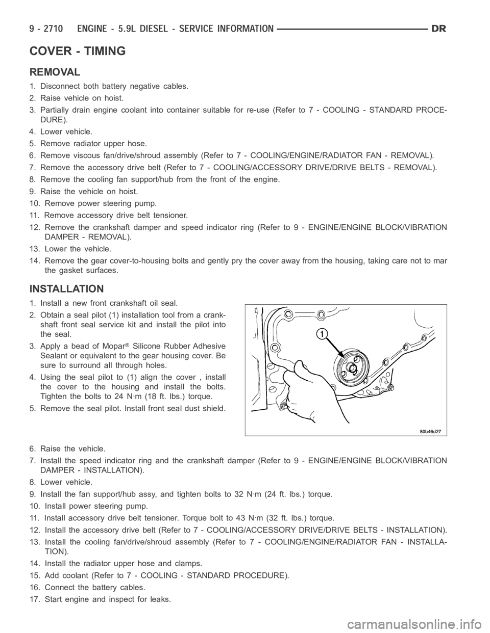
2. Obtain a seal pilot (1) installation tool from a crank-
shaft front seal service kit and install the pilot into
the seal.
3. Apply a bead of Mopar
Silicone Rubber Adhesive
Sealant or equivalent to the gear housing cover. Be
sure to surround all through holes.
4. Using the seal pilot to (1) align the cover , install
the cover to the housing and install the bolts.
Tighten the bolts to 24 Nꞏm (18 ft. lbs.) torque.
5. Remove the seal pilot. Install front seal dust shield.
6. Raise the vehicle.
7. Install the speed indicator ring and the crankshaft damper (Refer to 9 - ENGINE/ENGINE BLOCK/VIBRATION
DAMPER - INSTALLATION).
8. Lower vehicle.
9. Install the fan support/hub assy, and tighten bolts to 32 Nꞏm (24 ft. lbs.) torque.
10. Install power steering pump.
11. Install accessory drive belt tensioner. Torque bolt to 43 Nꞏm (32 ft. lbs.) torque.
12. Install the accessory drive belt (Refer to 7 - COOLING/ACCESSORY DRIVE/DRIVE BELTS - INSTALLATION).
13. Install the cooling fan/drive/shroud assembly (Refer to 7 - COOLING/ENGINE/RADIATOR FAN - INSTALLA-
TION).
14. Install the radiator upper hose and clamps.
15. Add coolant (Refer to 7 - COOLING - STANDARD PROCEDURE).
16. Connect the battery cables.
17. Start engine and inspect for leaks.
Page 2033 of 5267
5. Identify the fluid in the cylinder(s) (i.e., coolant, fuel, oil or other).
6. Make sure all fluid has been removed from the cylinders. Inspect engine for damage (i.e., connecting rods, pis-
tons, valves, etc.)
7. Repair engine or components as necessary to prevent this problem from re-occurring.
CAUTION: Squirt approximately one teaspoon of oil into the cylinders, rotateenginetolubricatethecylin-
der walls to prevent damage on restart.
8. Install new spark plugs.
9. Drain engine oil and remove oil filter.
10. Fill engine with specified amount of approved oil and install new oil filter.
11. Connect negative battery cable.
12. Start engine and check for any leaks.
REMOVAL - ENGINE ASSEMBLY
1. Perform fuel pressure release procedure (Refer to
14 - FUEL SYSTEM/FUEL DELIVERY - STAN-
DARD PROCEDURE).
2. Disconnect negative battery cable.
3. Disconnect throttle body air inlet duct, remove air
cleaner cover (Refer to 9 - ENGINE/AIR INTAKE
SYSTEM/AIR CLEANER ELEMENT - REMOVAL).
4. Raise and support the vehicle.
5. Remove the lower engine shield.
6. Drain cooling system (Refer to 7 - COOLING/EN-
GINE - STANDARD PROCEDURE - DRAINING
COOLING SYSTEM).
7. Paint mark and remove the driveshaft (Refer to 3 -
DIFFERENTIAL & DRIVELINE/PROPELLER
SHAFT/PROPELLER SHAFT - REMOVAL).
8.Removethetransmission(Referto21-TRANS-
MISSION/TRANSAXLE/MANUAL - REMOVAL).
9. Remove the starter (Refer to 8 - ELECTRICAL/
STARTING/STARTER MOTOR - REMOVAL).
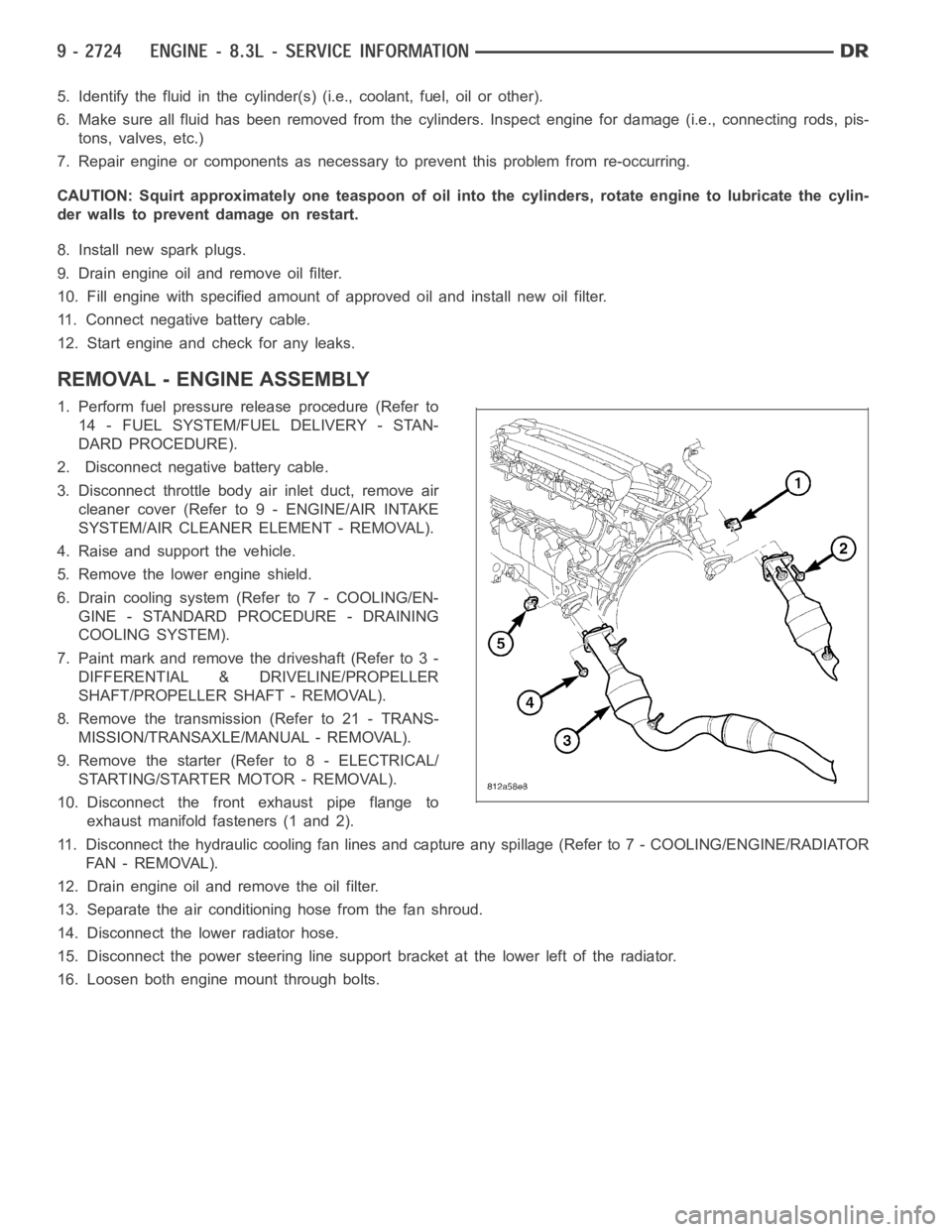
10. Disconnect the front exhaust pipe flange to
exhaust manifold fasteners (1 and 2).
11. Disconnect the hydraulic cooling fan lines and capture any spillage (Refer to 7 - COOLING/ENGINE/RADIATOR
FA N - R E M O VA L ) .
12. Drain engine oil and remove the oil filter.
13. Separate the air conditioning hose from the fan shroud.
14. Disconnect the lower radiator hose.
15. Disconnect the power steering line support bracket at the lower left ofthe radiator.
16. Loosen both engine mount through bolts.
Page 2034 of 5267
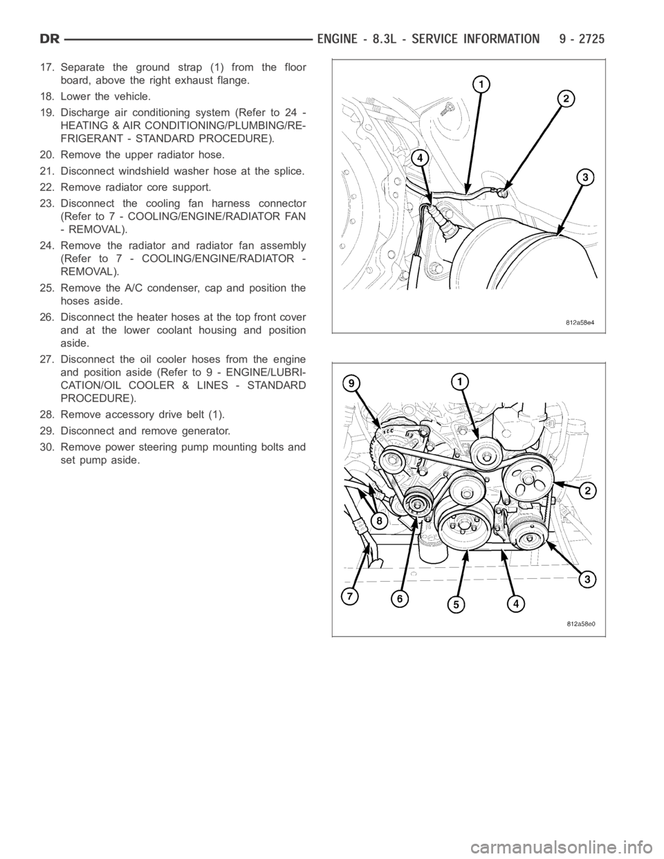
17. Separate the ground strap (1) from the floor
board, above the right exhaust flange.
18. Lower the vehicle.
19. Discharge air conditioning system (Refer to 24 -
HEATING & AIR CONDITIONING/PLUMBING/RE-
FRIGERANT - STANDARD PROCEDURE).
20. Remove the upper radiator hose.
21. Disconnect windshield washer hose at the splice.
22. Remove radiator core support.
23. Disconnect the cooling fan harness connector
(Refer to 7 - COOLING/ENGINE/RADIATOR FAN
- REMOVAL).
24. Remove the radiator and radiator fan assembly
(Refer to 7 - COOLING/ENGINE/RADIATOR -
REMOVAL).
25. Remove the A/C condenser, cap and position the
hoses aside.
26. Disconnect the heater hoses at the top front cover
and at the lower coolant housing and position
aside.
27. Disconnect the oil cooler hoses from the engine
and position aside (Refer to 9 - ENGINE/LUBRI-
CATION/OIL COOLER & LINES - STANDARD
PROCEDURE).
28. Remove accessory drive belt (1).
29. Disconnect and remove generator.
30. Remove power steering pump mounting bolts and
set pump aside.
Page 2038 of 5267
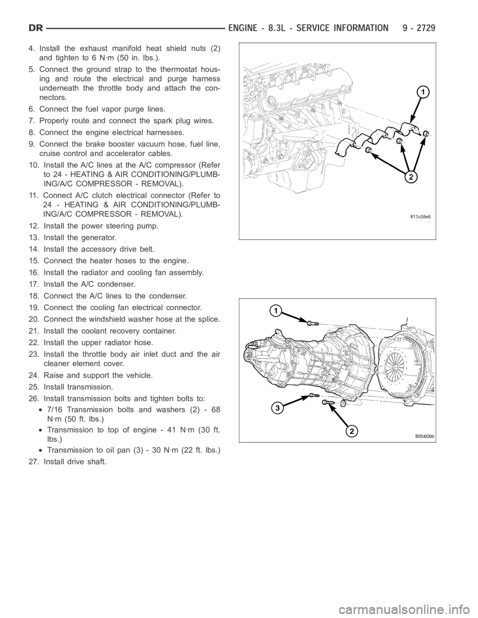
4. Install the exhaust manifold heat shield nuts (2)
and tighten to 6 Nꞏm (50 in. lbs.).
5. Connect the ground strap to the thermostat hous-
ing and route the electrical and purge harness
underneath the throttle body and attach the con-
nectors.
6. Connect the fuel vapor purge lines.
7. Properly route and connect the spark plug wires.
8. Connect the engine electrical harnesses.
9. Connect the brake booster vacuum hose, fuel line,
cruise control and accelerator cables.
10. Install the A/C lines at the A/C compressor (Refer
to 24 - HEATING & AIR CONDITIONING/PLUMB-
ING/A/C COMPRESSOR - REMOVAL).
11. Connect A/C clutch electrical connector (Refer to
24 - HEATING & AIR CONDITIONING/PLUMB-
ING/A/C COMPRESSOR - REMOVAL).
12. Install the power steering pump.
13. Install the generator.
14. Install the accessory drive belt.
15. Connect the heater hoses to the engine.
16. Install the radiator and cooling fan assembly.
17. Install the A/C condenser.
18. Connect the A/C lines to the condenser.
19. Connect the cooling fan electrical connector.
20. Connect the windshield washer hose at the splice.
21. Install the coolant recovery container.
22. Install the upper radiator hose.
23. Install the throttle body air inlet duct and the air
cleaner element cover.
24. Raise and support the vehicle.
25. Install transmission.
26. Install transmission bolts and tighten bolts to:
7/16 Transmission bolts and washers (2) - 68
Nꞏm (50 ft. lbs.)
Transmission to top of engine - 41 Nꞏm (30 ft.
lbs.)
Transmission to oil pan (3) - 30 Nꞏm (22 ft. lbs.)
27. Install drive shaft.
Page 2040 of 5267
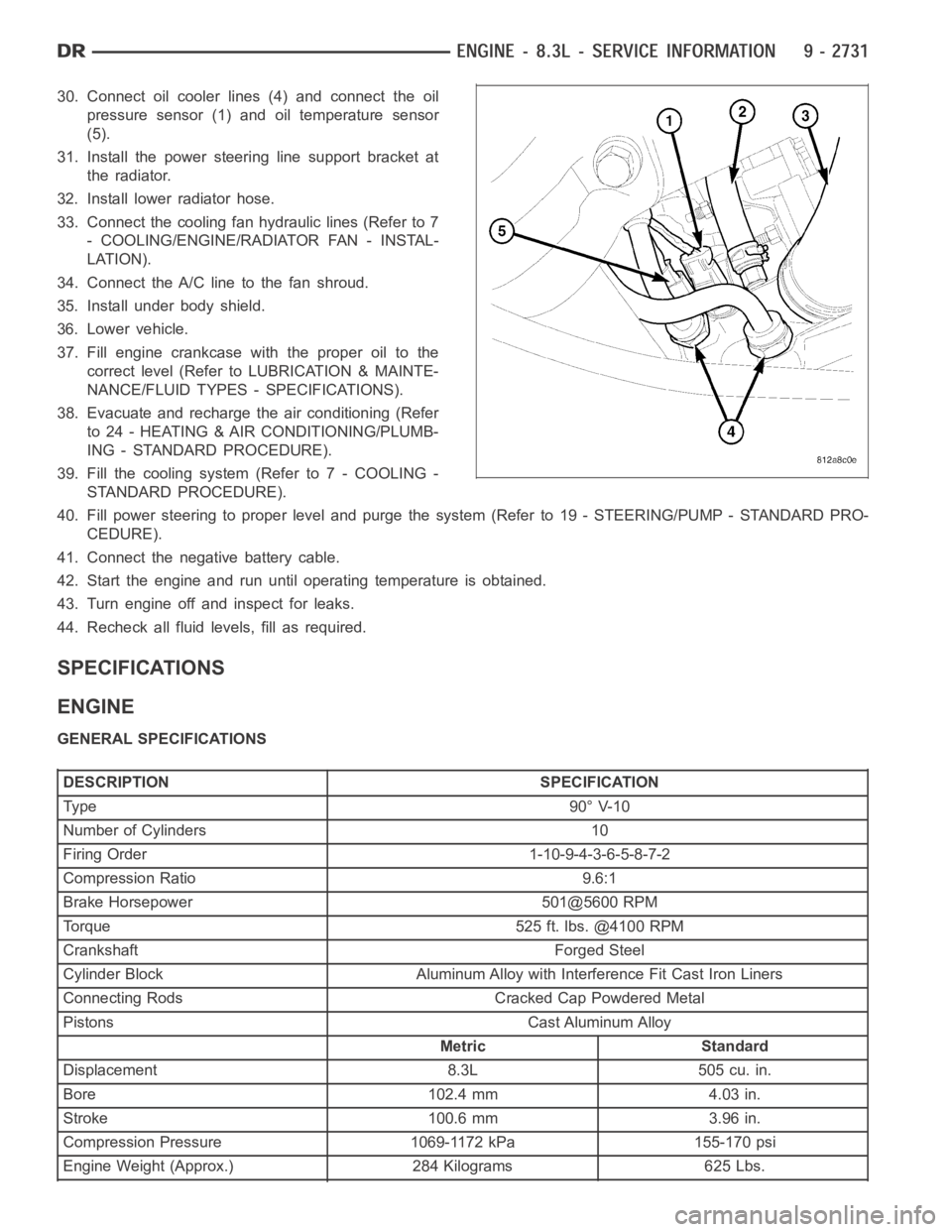
30. Connect oil cooler lines (4) and connect the oil
pressure sensor (1) and oil temperature sensor
(5).
31. Install the power steering line support bracket at
the radiator.
32. Install lower radiator hose.
33. Connect the cooling fan hydraulic lines (Refer to 7
- COOLING/ENGINE/RADIATOR FAN - INSTAL-
LATION).
34. Connect the A/C line to the fan shroud.
35. Install under body shield.
36. Lower vehicle.
37. Fill engine crankcase with the proper oil to the
correct level (Refer to LUBRICATION & MAINTE-
NANCE/FLUID TYPES - SPECIFICATIONS).
38. Evacuate and recharge the air conditioning (Refer
to 24 - HEATING & AIR CONDITIONING/PLUMB-
ING - STANDARD PROCEDURE).
39. Fill the cooling system (Refer to 7 - COOLING -
STANDARD PROCEDURE).
40. Fill power steering to proper leveland purge the system (Refer to 19 - STEERING/PUMP - STANDARD PRO-
CEDURE).
41. Connect the negative battery cable.
42. Start the engine and run until operating temperature is obtained.
43. Turn engine off and inspect for leaks.
44. Recheck all fluid levels, fill as required.
SPECIFICATIONS
ENGINE
GENERAL SPECIFICATIONS
DESCRIPTION SPECIFICATION
Ty pe 9 0° V-1 0
Number of Cylinders 10
Firing Order 1-10-9-4-3-6-5-8-7-2
Compression Ratio 9.6:1
Brake Horsepower 501@5600 RPM
Torque 525 ft. lbs. @4100 RPM
Crankshaft Forged Steel
Cylinder Block Aluminum Alloy with Interference Fit Cast Iron Liners
Connecting Rods Cracked Cap Powdered Metal
Pistons Cast Aluminum Alloy
Metric Standard
Displacement 8.3L 505 cu. in.
Bore 102.4 mm 4.03 in.
Stroke 100.6 mm 3.96 in.
Compression Pressure 1069-1172 kPa 155-170 psi
Engine Weight (Approx.) 284 Kilograms 625 Lbs.
Page 2078 of 5267
COVER-TIMING CHAIN
REMOVAL
1. Disconnect negative battery cable.
2. Disconnect throttle body air inlet duct at the throttle
body, CCV hose, disconnect the IAT sensor and
remove air cleaner housing cover (Refer to 9 -
ENGINE/AIR INTAKE SYSTEM - REMOVAL).
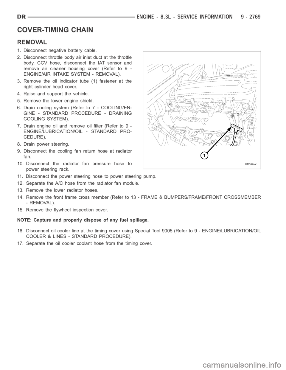
3. Remove the oil indicator tube (1) fastener at the
right cylinder head cover.
4. Raise and support the vehicle.
5. Remove the lower engine shield.
6. Drain cooling system (Refer to 7 - COOLING/EN-
GINE - STANDARD PROCEDURE - DRAINING
COOLING SYSTEM).
7. Drain engine oil and remove oil filter (Refer to 9 -
ENGINE/LUBRICATION/OIL - STANDARD PRO-
CEDURE).
8. Drain power steering.
9. Disconnect the cooling fan return hose at radiator
fan.
10. Disconnect the radiator fan pressure hose to
power steering rack.
11. Disconnect the power steering hose to power steering pump.
12. Separate the A/C hose from the radiator fan module.
13. Remove the lower radiator hoses.
14. Remove the front frame cross member (Refer to 13 - FRAME & BUMPERS/FRAME/FRONT CROSSMEMBER
- REMOVAL).
15. Remove the flywheel inspection cover.
NOTE: Capture and properly dispose of any fuel spillage.
16. Disconnect oil cooler line at the timing cover using Special Tool 9005 (Refer to 9 - ENGINE/LUBRICATION/OIL
COOLER & LINES - STANDARD PROCEDURE).
17. Separate the oil cooler coolant hose from the timing cover.
Page 2080 of 5267
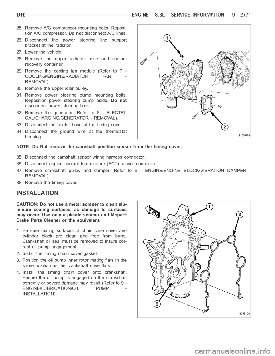
25. Remove A/C compressor mounting bolts. Reposi-
tion A/C compressor.Do notdisconnect A/C lines.
26. Disconnect the power steering line support
bracket at the radiator.
27. Lower the vehicle.
28. Remove the upper radiator hose and coolant
recovery container.
29. Remove the cooling fan module (Refer to 7 -
COOLING/ENGINE/RADIATOR FAN -
REMOVAL).
30. Remove the upper idler pulley.
31. Remove power steering pump mounting bolts.
Reposition power steering pump aside.Do not
disconnect power steering lines.
32. Remove the generator (Refer to 8 - ELECTRI-
CAL/CHARGING/GENERATOR - REMOVAL).
33. Disconnect the heater hose at the timing cover.
34. Disconnect the ground wire at the thermostat
housing.
NOTE: Do Not remove the camshaft position sensor from the timing cover.
35. Disconnect the camshaft sensor wiring harness connector.
36. Disconnect engine coolant temperature (ECT) sensor connector.
37. Remove crankshaft pulley and damper (Refer to 9 - ENGINE/ENGINE BLOCK/VIBRATION DAMPER -
REMOVAL).
38. Remove the timing cover.
INSTALLATION
CAUTION: Do not use a metal scraper to clean alu-
minum sealing surfaces, as damage to surfaces
may occur. Use only a plastic scraper and Mopar
Brake Parts Cleaner or the equivalent.
1. Be sure mating surfaces of chain case cover and
cylinder block are clean and free from burrs.
Crankshaft oil seal must be removed to insure cor-
rect oil pump engagement.
2. Install the timing chain cover gasket.
3. Position the oil pump inner rotor mating flats in the
same position as the crankshaft drive flats.
4. Install the timing chain cover onto crankshaft.
Ensure the oil pump is engaged on the crankshaft
correctly or severe damage may result (Refer to 9 -
ENGINE/LUBRICATION/OIL PUMP -
INSTALLATION).
Page 2081 of 5267
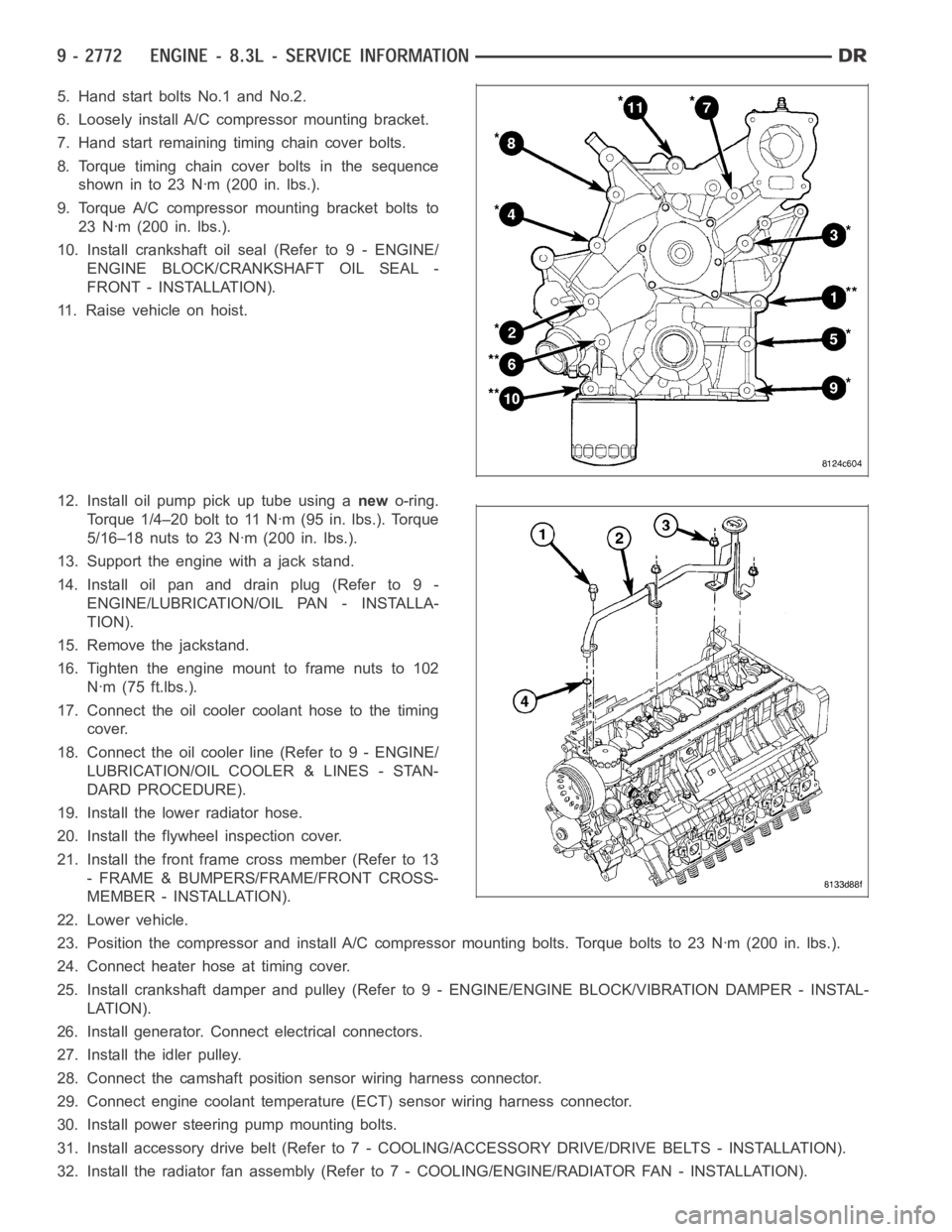
5. Hand start bolts No.1 and No.2.
6. Loosely install A/C compressor mounting bracket.
7. Hand start remaining timing chain cover bolts.
8. Torque timing chain cover bolts in the sequence
showninto23Nꞏm(200in.lbs.).
9. Torque A/C compressor mounting bracket bolts to
23 Nꞏm (200 in. lbs.).
10. Install crankshaft oil seal (Refer to 9 - ENGINE/
ENGINE BLOCK/CRANKSHAFT OIL SEAL -
FRONT - INSTALLATION).
11. Raise vehicle on hoist.
12. Install oil pump pick up tube using anewo-ring.
Torque 1/4–20 bolt to 11 Nꞏm (95 in. lbs.). Torque
5/16–18 nuts to 23 Nꞏm (200 in. lbs.).
13. Support the engine with a jack stand.
14. Install oil pan and drain plug (Refer to 9 -
ENGINE/LUBRICATION/OIL PAN - INSTALLA-
TION).
15. Remove the jackstand.
16. Tighten the engine mount to frame nuts to 102
Nꞏm (75 ft.lbs.).
17. Connect the oil cooler coolant hose to the timing
cover.
18. Connect the oil cooler line (Refer to 9 - ENGINE/
LUBRICATION/OIL COOLER & LINES - STAN-
DARD PROCEDURE).
19. Install the lower radiator hose.
20. Install the flywheel inspection cover.
21. Install the front frame cross member (Refer to 13
- FRAME & BUMPERS/FRAME/FRONT CROSS-
MEMBER - INSTALLATION).
22. Lower vehicle.
23. Position the compressor and install A/C compressor mounting bolts. Torque bolts to 23 Nꞏm (200 in. lbs.).
24. Connect heater hose at timing cover.
25. Install crankshaft damper and pulley (Refer to 9 - ENGINE/ENGINE BLOCK/VIBRATION DAMPER - INSTAL-
LATION).
26. Install generator. Connect electrical connectors.
27. Install the idler pulley.
28. Connect the camshaft position sensor wiring harness connector.
29. Connect engine coolant temperature (ECT) sensor wiring harness connector.
30. Install power steering pump mounting bolts.
31. Install accessory drive belt (Refer to 7 - COOLING/ACCESSORY DRIVE/DRIVE BELTS - INSTALLATION).
32. Install the radiator fan assembly (Refer to 7 - COOLING/ENGINE/RADIATOR FAN - INSTALLATION).