radiator DODGE RAM SRT-10 2006 Service Manual PDF
[x] Cancel search | Manufacturer: DODGE, Model Year: 2006, Model line: RAM SRT-10, Model: DODGE RAM SRT-10 2006Pages: 5267, PDF Size: 68.7 MB
Page 2082 of 5267
33. Raise and support the vehicle.
34. Connect the hydraulic lines to the fan assembly and steering rack then connect the A/C hose to the fan shroud.
35. Install aNewoil filter.
36. Lower the vehicle.
37. Install upper radiator hose and connect the ground wire at the thermostat housing.
38. Install air cleaner housing cover assembly, connect throttle body airinlet duct, IAT sensor and CCV hose. (Refer
to 9 - ENGINE/AIR INTAKE SYSTEM - INSTALLATION).
39. Fill and purge air from the power steering system.
40. Fill engine crankcase with proper oil to correct level.
41. Fill and purge air from the cooling system (Refer to 7 - COOLING/ENGINE -STANDARD PROCEDURE - FILL-
ING COOLING SYSTEM).
42. Connect negative battery cable.
43. Start the vehicle and inspect for leaks.
44. Install the lower engine shield.
Page 2108 of 5267
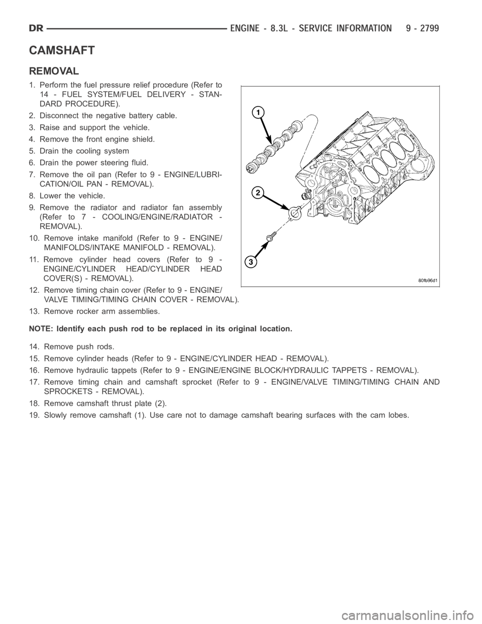
CAMSHAFT
REMOVAL
1. Perform the fuel pressure relief procedure (Refer to
14 - FUEL SYSTEM/FUEL DELIVERY - STAN-
DARD PROCEDURE).
2. Disconnect the negative battery cable.
3. Raise and support the vehicle.
4. Remove the front engine shield.
5. Drain the cooling system
6. Drain the power steering fluid.
7. Remove the oil pan (Refer to 9 - ENGINE/LUBRI-
CATION/OIL PAN - REMOVAL).
8. Lower the vehicle.
9. Remove the radiator and radiator fan assembly
(Refer to 7 - COOLING/ENGINE/RADIATOR -
REMOVAL).
10. Remove intake manifold (Refer to 9 - ENGINE/
MANIFOLDS/INTAKE MANIFOLD - REMOVAL).
11. Remove cylinder head covers (Refer to 9 -
ENGINE/CYLINDER HEAD/CYLINDER HEAD
COVER(S) - REMOVAL).
12. Remove timing chain cover (Refer to 9 - ENGINE/
VALVE TIMING/TIMING CHAIN COVER - REMOVAL).
13. Remove rocker arm assemblies.
NOTE: Identify each push rod to be replaced in its original location.
14. Remove push rods.
15. Remove cylinder heads (Refer to 9 - ENGINE/CYLINDER HEAD - REMOVAL).
16. Remove hydraulic tappets (Refer to 9 - ENGINE/ENGINE BLOCK/HYDRAULICTAPPETS - REMOVAL).
17. Remove timing chain and camshaft sprocket (Refer to 9 - ENGINE/VALVE TIMING/TIMING CHAIN AND
SPROCKETS - REMOVAL).
18. Remove camshaft thrust plate (2).
19. Slowly remove camshaft (1). Use care not to damage camshaft bearing surfaces with the cam lobes.
Page 2109 of 5267
INSTALLATION
1. Lubricate camshaft lobes and camshaft bearing
journals.
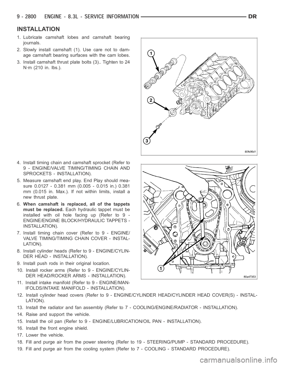
2. Slowly install camshaft (1). Use care not to dam-
age camshaft bearing surfaces with the cam lobes.
3. Install camshaft thrust plate bolts (3).. Tighten to 24
Nꞏm (210 in. lbs.).
4. Install timing chain and camshaft sprocket (Refer to
9 - ENGINE/VALVE TIMING/TIMING CHAIN AND
SPROCKETS - INSTALLATION).
5. Measure camshaft end play. End Play should mea-
sure 0.0127 - 0.381 mm (0.005 - 0.015 in.) 0.381
mm (0.015 in. Max.). If not within limits, install a
new thrust plate.
6.When camshaft is replaced, all of the tappets
must be replaced.Each hydraulic tappet must be
installed with oil hole facing up (Refer to 9 -
ENGINE/ENGINE BLOCK/HYDRAULIC TAPPETS -
INSTALLATION).
7. Install timing chain cover (Refer to 9 - ENGINE/
VALVE TIMING/TIMINGCHAIN COVER - INSTAL-
LATION).
8. Install cylinder heads (Refer to 9 - ENGINE/CYLIN-
DER HEAD - INSTALLATION).
9. Install push rods in their original location.
10. Install rocker arms (Refer to 9 - ENGINE/CYLIN-
DER HEAD/ROCKER ARMS - INSTALLATION).
11. Install intake manifold (Refer to 9 - ENGINE/MAN-
IFOLDS/INTAKE MANIFOLD - INSTALLATION).
12. Install cylinder head covers (Refer to 9 - ENGINE/CYLINDER HEAD/CYLINDER HEAD COVER(S) - INSTAL-
LATION).
13. Install the radiator and fan assembly (Refer to 7 - COOLING/ENGINE/RADIATOR - INSTALLATION).
14. Raise and support the vehicle.
15. Install the oil pan (Refer to 9 - ENGINE/LUBRICATION/OIL PAN - INSTALLATION).
16. Install the front engine shield.
17. Lower the vehicle.
18. Fill and purge air from the power steering (Refer to 19 - STEERING/PUMP -STANDARD PROCEDURE).
19. Fill and purge air from the coolingsystem (Refer to 7 - COOLING - STANDARD PROCEDURE).
Page 2121 of 5267
DAMPER-CRANKSHAFT
REMOVAL
1. Raise and support the vehicle.
2. Remove the engine front shield.
3. Disconnect the radiator fan hydraulic lines (Refer to
7 - COOLING/ENGINE/RADIATOR FAN -
REMOVAL).
4. Lower vehicle.
5. Disconnect the air inlet duct, IAT sensor, CCV hose
at the throttle body, and remove the air cleaner
housing cover.
6. Remove accessory drive belt (Refer to 7 - COOL-
ING/ACCESSORY DRIVE/DRIVE BELTS -
REMOVAL).
7. Remove the radiator fan (Refer to 7 - COOLING/
ENGINE/RADIATOR FAN - REMOVAL).
8. Raise and support the vehicle.
9. Remove crankshaft pulley.
10. Remove crankshaft damper bolt.
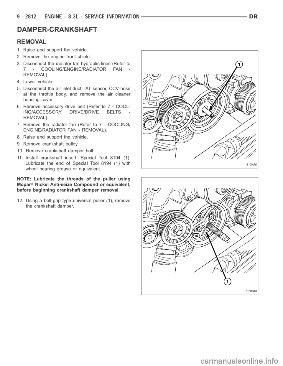
11. Install crankshaft insert, Special Tool 8194 (1).
Lubricate the end of Special Tool 8194 (1) with
wheel bearing grease or equivalent.
NOTE: Lubricate the threads of the puller using
Mopar
Nickel Anti-seize Compound or equivalent,
before beginning crankshaft damper removal.
12. Using a bolt-grip type universal puller (1), remove
the crankshaft damper.
Page 2122 of 5267
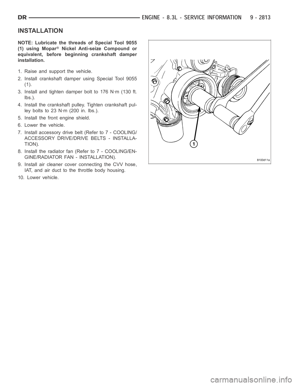
INSTALLATION
NOTE: Lubricate the threads of Special Tool 9055
(1) using Mopar
Nickel Anti-seize Compound or
equivalent, before beginning crankshaft damper
installation.
1. Raise and support the vehicle.
2. Install crankshaft damper using Special Tool 9055
(1).
3. Install and tighten damper bolt to 176 Nꞏm (130 ft.
lbs.).
4. Install the crankshaft pulley. Tighten crankshaft pul-
ley bolts to 23 Nꞏm (200 in. lbs.).
5. Install the front engine shield.
6. Lower the vehicle.
7. Install accessory drive belt (Refer to 7 - COOLING/
ACCESSORY DRIVE/DRIVE BELTS - INSTALLA-
TION).
8. Install the radiator fan (Refer to 7 - COOLING/EN-
GINE/RADIATOR FAN - INSTALLATION).
9. Install air cleaner cover connecting the CVV hose,
IAT, and air duct to the throttle body housing.
10. Lower vehicle.
Page 2169 of 5267
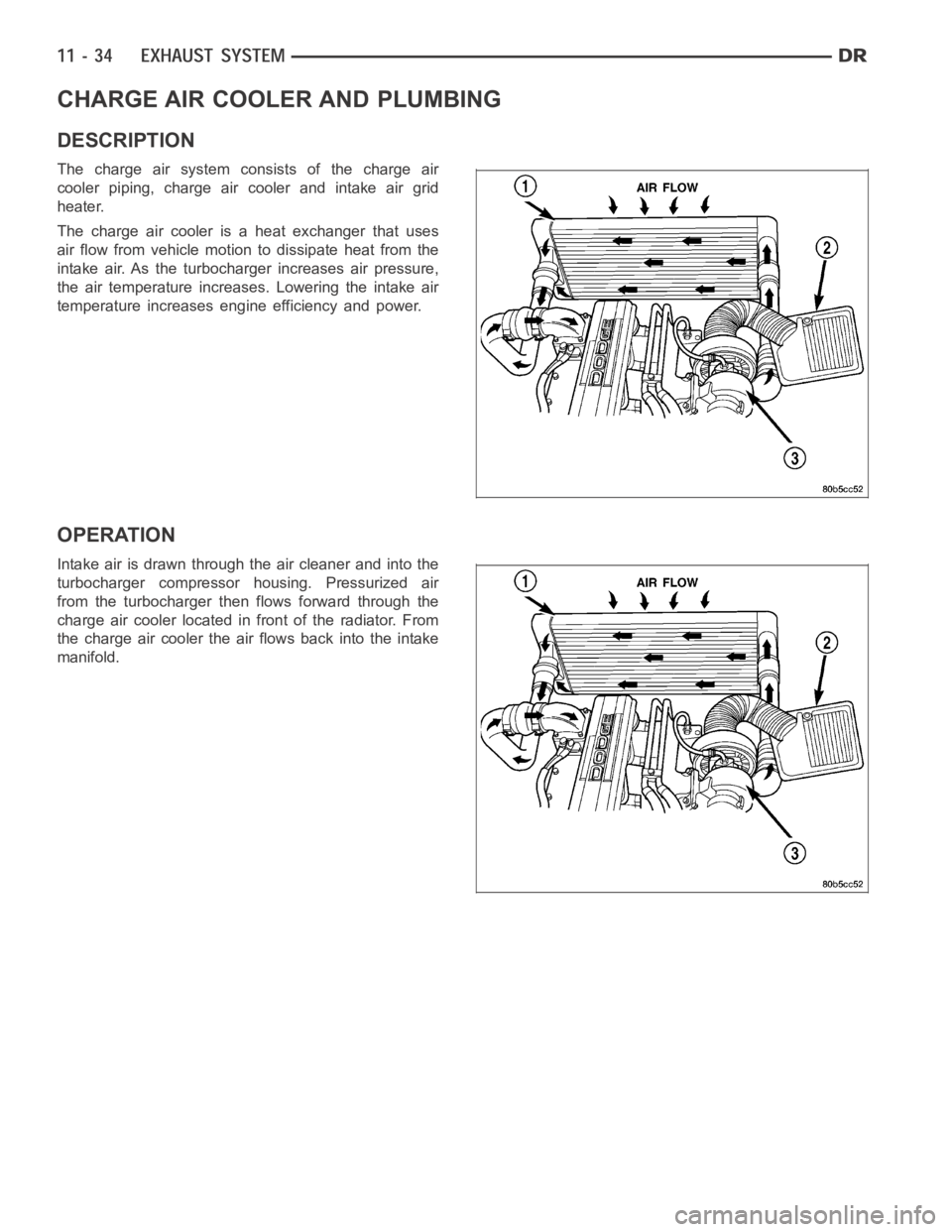
CHARGE AIR COOLER AND PLUMBING
DESCRIPTION
The charge air system consists of the charge air
cooler piping, charge air cooler and intake air grid
heater.
The charge air cooler is a heat exchanger that uses
air flow from vehicle motion to dissipate heat from the
intake air. As the turbocharger increases air pressure,
the air temperature increases. Lowering the intake air
temperature increases engine efficiency and power.
OPERATION
Intake air is drawn through the air cleaner and into the
turbocharger compressor housing. Pressurized air
from the turbocharger then flows forward through the
charge air cooler located in front of the radiator. From
the charge air cooler the air flows back into the intake
manifold.
Page 2192 of 5267
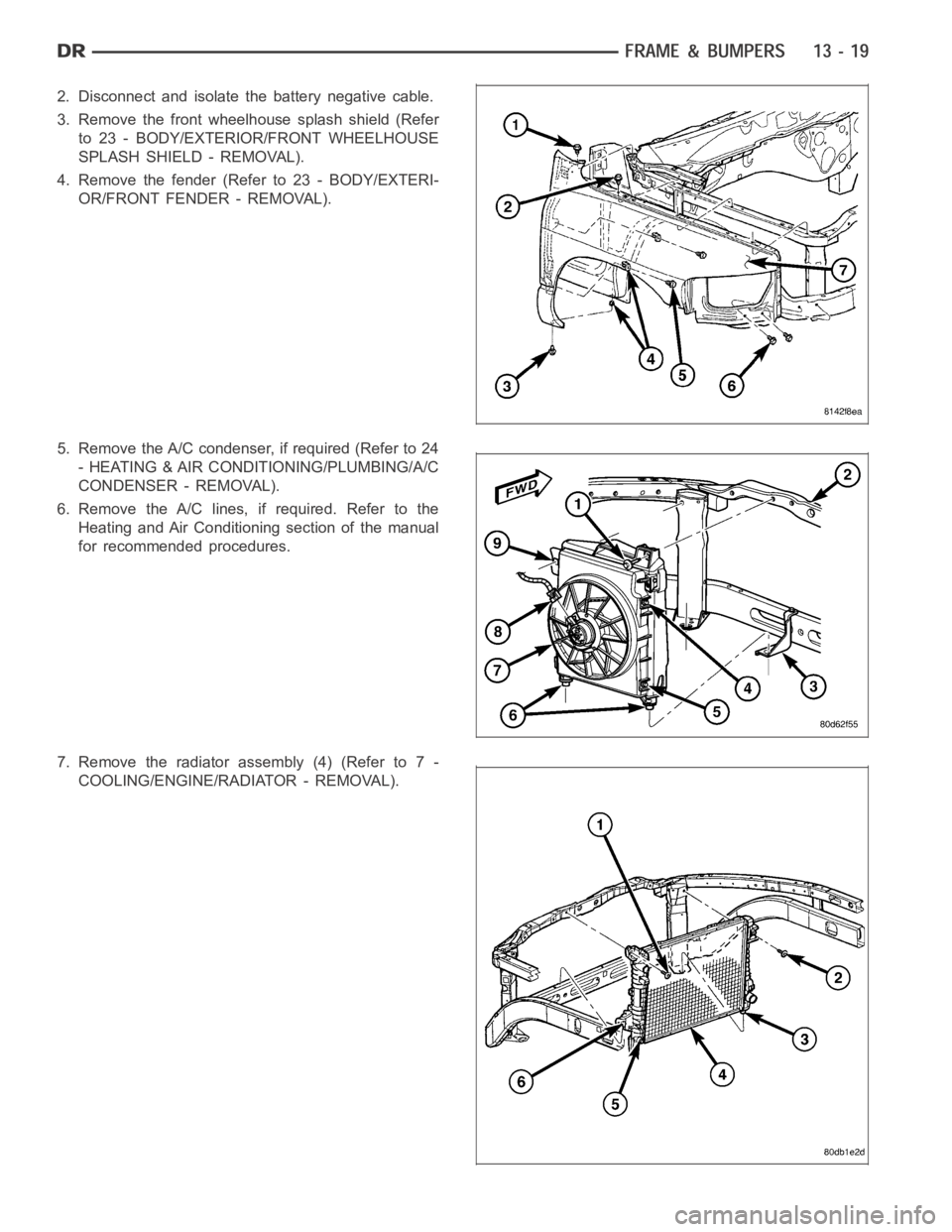
2. Disconnect and isolate the battery negative cable.
3. Remove the front wheelhouse splash shield (Refer
to 23 - BODY/EXTERIOR/FRONT WHEELHOUSE
SPLASH SHIELD - REMOVAL).
4. Remove the fender (Refer to 23 - BODY/EXTERI-
OR/FRONT FENDER - REMOVAL).
5. Remove the A/C condenser, if required (Refer to 24
- HEATING & AIR CONDITIONING/PLUMBING/A/C
CONDENSER - REMOVAL).
6. Remove the A/C lines, if required. Refer to the
Heating and Air Conditioning section of the manual
for recommended procedures.
7. Remove the radiator assembly (4) (Refer to 7 -
COOLING/ENGINE/RADIATOR - REMOVAL).
Page 2194 of 5267
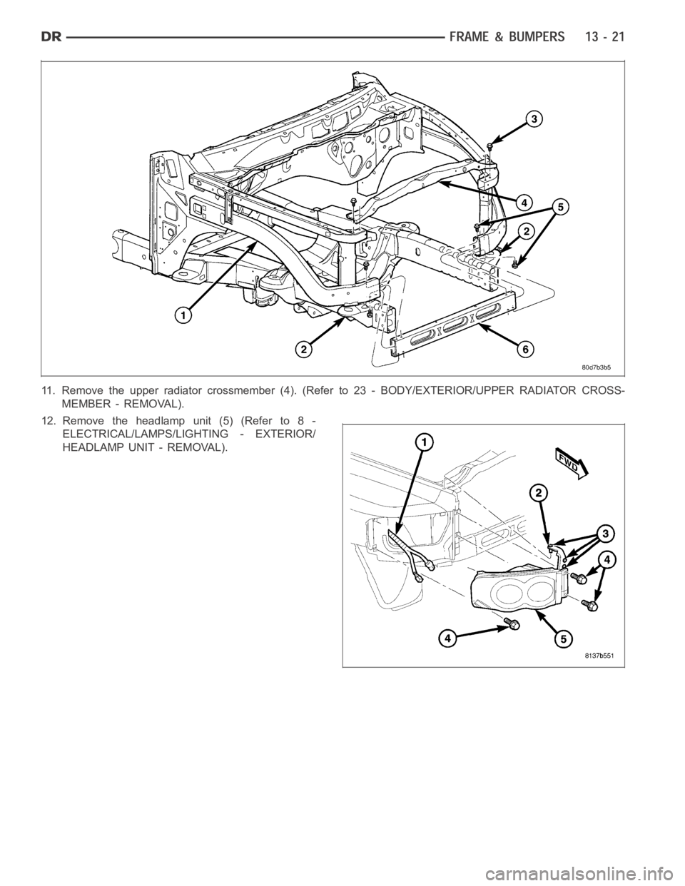
11. Remove the upper radiator crossmember (4). (Refer to 23 - BODY/EXTERIOR/UPPER RADIATOR CROSS-
MEMBER - REMOVAL).
12. Remove the headlamp unit (5) (Refer to 8 -
ELECTRICAL/LAMPS/LIGHTING - EXTERIOR/
HEADLAMP UNIT - REMOVAL).
Page 2195 of 5267
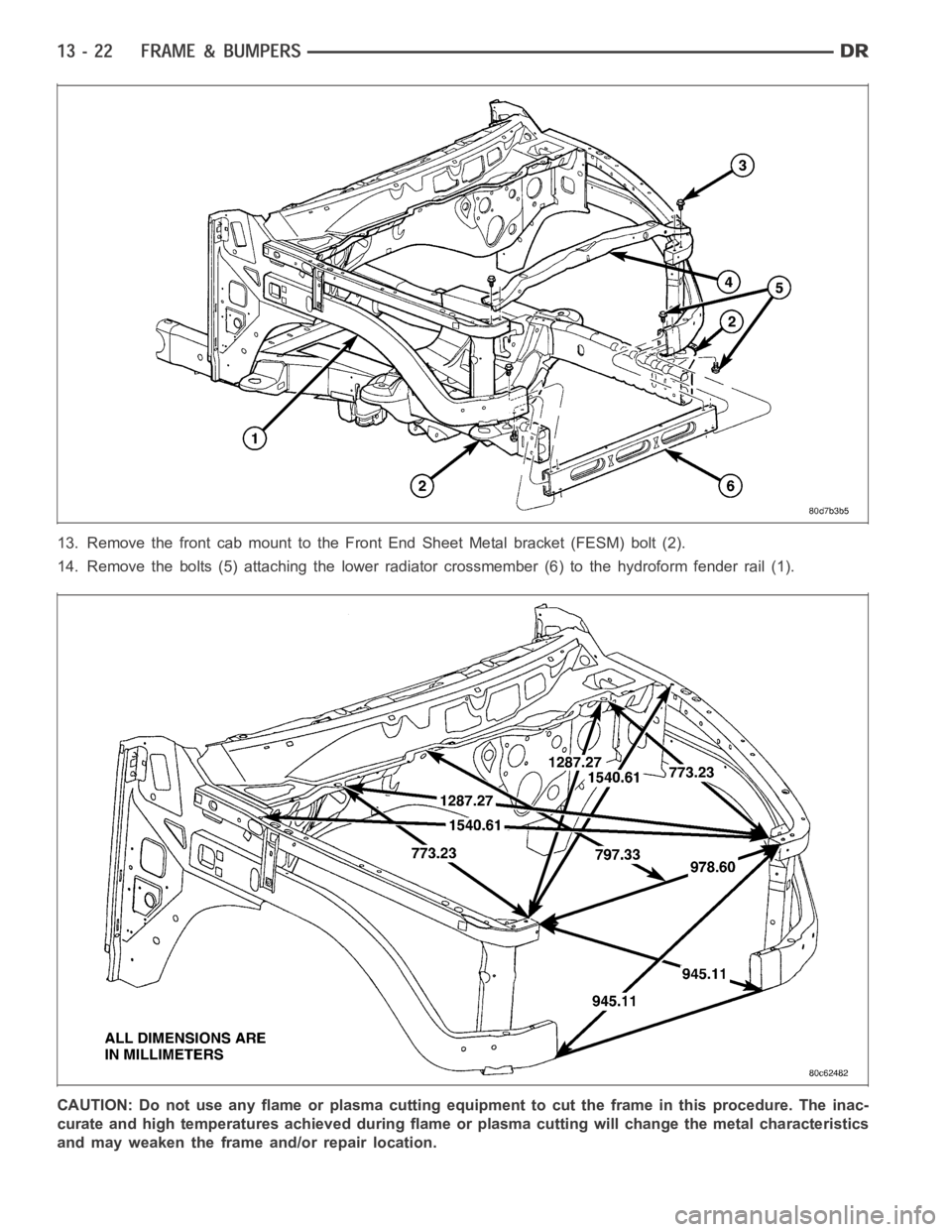
13. Remove the front cab mount to the Front End Sheet Metal bracket (FESM) bolt (2).
14. Remove the bolts (5) attaching the lower radiator crossmember (6) to the hydroform fender rail (1).
CAUTION: Do not use any flame or plasma cutting equipment to cut the frame inthis procedure. The inac-
curate and high temperatures achieved during flame or plasma cutting willchange the metal characteristics
and may weaken the frame and/or repair location.
Page 2196 of 5267
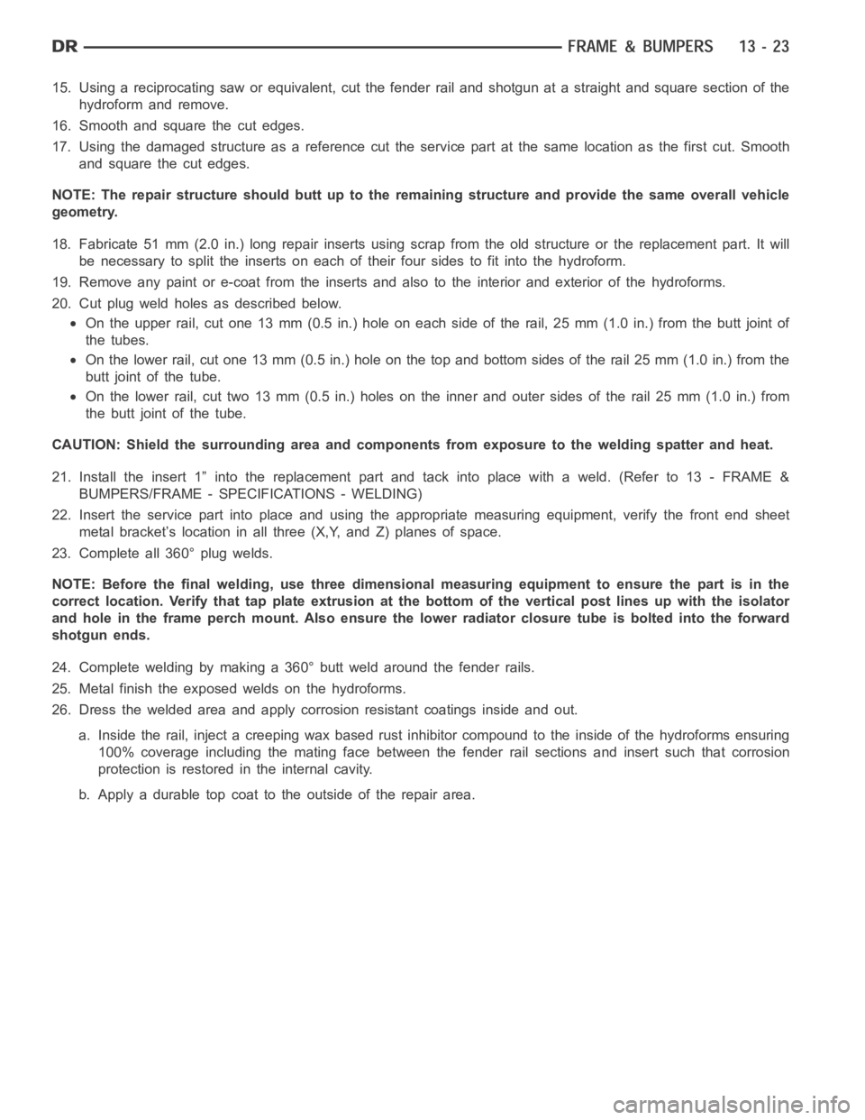
15. Using a reciprocating saw or equivalent, cut the fender rail and shotgun at a straight and square section of the
hydroform and remove.
16. Smooth and square the cut edges.
17. Using the damaged structure as a reference cut the service part at the same location as the first cut. Smooth
and square the cut edges.
NOTE: The repair structure should butt up to the remaining structure and provide the same overall vehicle
geometry.
18. Fabricate 51 mm (2.0 in.) long repair inserts using scrap from the old structure or the replacement part. It will
be necessary to split the inserts on each of their four sides to fit into the hydroform.
19. Remove any paint or e-coat from the inserts and also to the interior and exterior of the hydroforms.
20. Cut plug weld holes as described below.
On the upper rail, cut one 13 mm (0.5 in.) hole on each side of the rail, 25 mm (1.0 in.) from the butt joint of
the tubes.
On the lower rail, cut one 13 mm (0.5 in.) hole on the top and bottom sides of therail25mm(1.0in.)fromthe
butt joint of the tube.
On the lower rail, cut two 13 mm (0.5 in.) holes on the inner and outer sides oftherail25mm(1.0in.)from
the butt joint of the tube.
CAUTION: Shield the surrounding area and components from exposure to the welding spatter and heat.
21. Install the insert 1” into the replacement part and tack into place witha weld. (Refer to 13 - FRAME &
BUMPERS/FRAME - SPECIFICATIONS - WELDING)
22. Insert the service part into place and using the appropriate measuringequipment, verify the front end sheet
metal bracket’s location in all three (X,Y, and Z) planes of space.
23. Complete all 360° plug welds.
NOTE: Before the final welding, use three dimensional measuring equipment to ensure the part is in the
correct location. Verify that tap plate extrusion at the bottom of the vertical post lines up with the isolator
and hole in the frame perch mount. Also ensure the lower radiator closure tube is bolted into the forward
shotgun ends.
24. Complete welding by making a 360° butt weld around the fender rails.
25. Metal finish the exposed welds on the hydroforms.
26. Dress the welded area and apply corrosion resistant coatings inside and out.
a. Inside the rail, inject a creeping wax based rust inhibitor compound to the inside of the hydroforms ensuring
100% coverage including the mating face between the fender rail sections and insert such that corrosion
protection is restored in the internal cavity.
b. Apply a durable top coat to the outside of the repair area.