brake light DODGE RAM SRT-10 2006 Service User Guide
[x] Cancel search | Manufacturer: DODGE, Model Year: 2006, Model line: RAM SRT-10, Model: DODGE RAM SRT-10 2006Pages: 5267, PDF Size: 68.7 MB
Page 455 of 5267
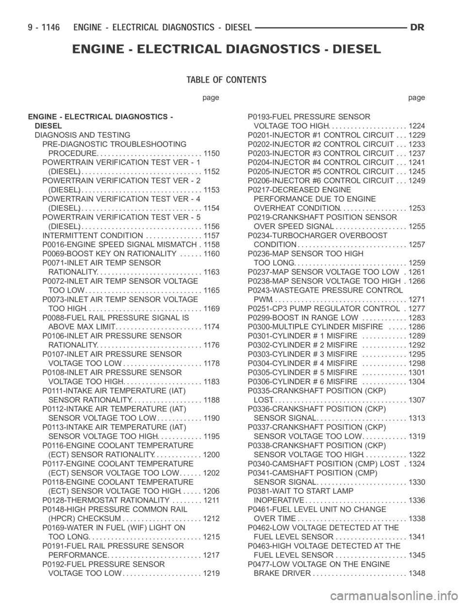
page page
ENGINE - ELECTRICAL DIAGNOSTICS -
DIESEL
DIAGNOSIS AND TESTING
PRE-DIAGNOSTIC TROUBLESHOOTING
PROCEDURE............................. 1150
POWERTRAIN VERIFICATION TEST VER - 1
(DIESEL)................................. 1152
POWERTRAIN VERIFICATION TEST VER - 2
(DIESEL)................................. 1153
POWERTRAIN VERIFICATION TEST VER - 4
(DIESEL)................................. 1154
POWERTRAIN VERIFICATION TEST VER - 5
(DIESEL)................................. 1156
INTERMITTENT CONDITION ............... 1157
P0016-ENGINE SPEED SIGNAL MISMATCH . 1158
P0069-BOOST KEY ON RATIONALITY ...... 1160
P0071-INLET AIR TEMP SENSOR
RATIONALITY............................ 1163
P0072-INLET AIR TEMP SENSOR VOLTAGE
TOO LOW................................ 1165
P0073-INLET AIR TEMP SENSOR VOLTAGE
TOO HIGH............................... 1169
P0088-FUEL RAIL PRESSURE SIGNAL IS
ABOVE MAX LIMIT........................ 1174
P0106-INLET AIR PRESSURE SENSOR
RATIONALITY............................ 1176
P0107-INLET AIR PRESSURE SENSOR
VOLTAGE TOO LOW...................... 1178
P0108-INLET AIR PRESSURE SENSOR
VOLTAGE TOO HIGH...................... 1183
P0111-INTAKE AIR TEMPERATURE (IAT)
SENSOR RATIONALITY................... 1188
P0112-INTAKE AIR TEMPERATURE (IAT)
SENSOR VOLTAGE TOO LOW............. 1190
P0113-INTAKE AIR TEMPERATURE (IAT)
SENSOR VOLTAGE TOO HIGH............. 1195
P0116-ENGINE COOLANT TEMPERATURE
(ECT) SENSOR RATIONALITY............. 1200
P0117-ENGINE COOLANT TEMPERATURE
(ECT) SENSOR VOLTAGE TOO LOW....... 1202
P0118-ENGINE COOLANT TEMPERATURE
(ECT) SENSOR VOLTAGE TOO HIGH...... 1206
P0128-THERMOSTAT RATIONALITY ........ 1211
P0148-HIGH PRESSURE COMMON RAIL
(HPCR) CHECKSUM...................... 1212
P0169-WATER IN FUEL (WIF) LIGHT ON
TOO LONG............................... 1215
P0191-FUEL RAIL PRESSURE SENSOR
PERFORMANCE.......................... 1217
P0192-FUEL PRESSURE SENSOR
VOLTAGE TOO LOW...................... 1219P0193-FUEL PRESSURE SENSOR
VOLTAGE TOO HIGH...................... 1224
P0201-INJECTOR #1 CONTROL CIRCUIT . . . 1229
P0202-INJECTOR #2 CONTROL CIRCUIT . . . 1233
P0203-INJECTOR #3 CONTROL CIRCUIT . . . 1237
P0204-INJECTOR #4 CONTROL CIRCUIT . . . 1241
P0205-INJECTOR #5 CONTROL CIRCUIT . . . 1245
P0206-INJECTOR #6 CONTROL CIRCUIT . . . 1249
P0217-DECREASED ENGINE
PERFORMANCE DUE TO ENGINE
OVERHEAT CONDITION................... 1253
P0219-CRANKSHAFT POSITION SENSOR
OVER SPEED SIGNAL.................... 1255
P0234-TURBOCHARGER OVERBOOST
CONDITION.............................. 1257
P0236-MAP SENSOR TOO HIGH
TOO LONG............................... 1259
P0237-MAP SENSOR VOLTAGE TOO LOW . 1261
P0238-MAP SENSOR VOLTAGE TOO HIGH . 1266
P0243-WASTEGATE PRESSURE CONTROL
PWM.................................... 1271
P0251-CP3 PUMP REGULATOR CONTROL . 1277
P0299-BOOST IN RANGE LOW ............ 1283
P0300-MULTIPLE CYLINDER MISFIRE ..... 1286
P0301-CYLINDER # 1 MISFIRE ............ 1289
P0302-CYLINDER # 2 MISFIRE ............ 1292
P0303-CYLINDER # 3 MISFIRE ............ 1295
P0304-CYLINDER # 4 MISFIRE ............ 1298
P0305-CYLINDER # 5 MISFIRE ............ 1301
P0306-CYLINDER # 6 MISFIRE ............ 1304
P0335-CRANKSHAFT POSITION (CKP)
LOST.................................... 1307
P0336-CRANKSHAFT POSITION (CKP)
SENSOR SIGNAL......................... 1313
P0337-CRANKSHAFT POSITION (CKP)
SENSOR VOLTAGE TOO LOW............. 1319
P0338-CRANKSHAFT POSITION (CKP)
SENSOR VOLTAGE TOO HIGH............ 1322
P0340-CAMSHAFT POSITION (CMP) LOST . 1324
P0341-CAMSHAFT POSITION (CMP)
SENSOR SIGNAL......................... 1330
P0381-WAIT TO START LAMP
INOPERATIVE............................ 1336
P0461-FUEL LEVEL UNIT NO CHANGE
OVER TIME.............................. 1338
P0462-LOW VOLTAGE DETECTED AT THE
FUEL LEVEL SENSOR.................... 1341
P0463-HIGH VOLTAGE DETECTED AT THE
FUEL LEVEL SENSOR.................... 1345
P0477-LOW VOLTAGE ON THE ENGINE
BRAKE DRIVER.......................... 1348
Page 463 of 5267
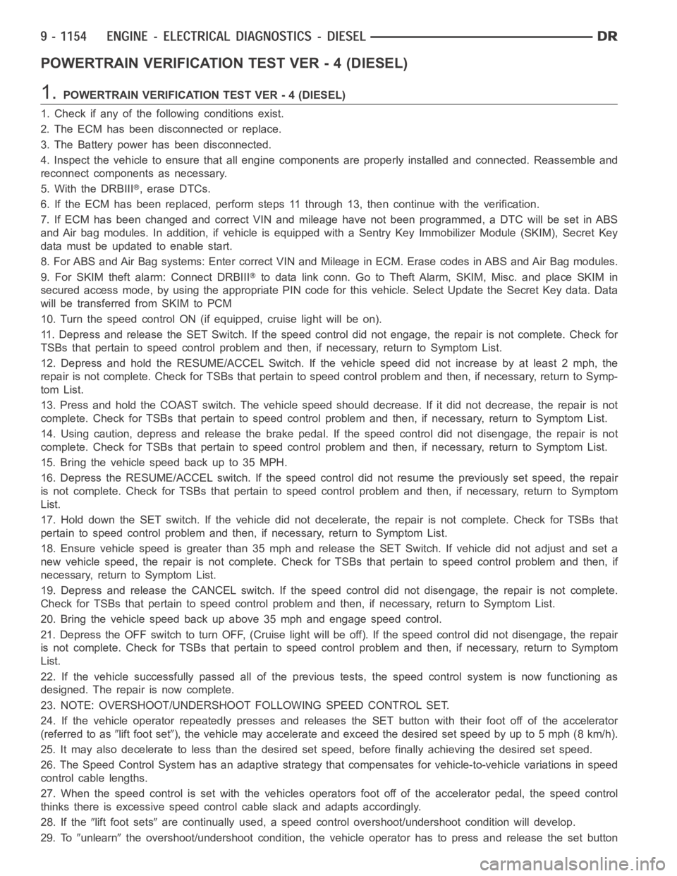
POWERTRAIN VERIFICATION TEST VER - 4 (DIESEL)
1.POWERTRAIN VERIFICATION TEST VER - 4 (DIESEL)
1. Check if any of the following conditions exist.
2. The ECM has been disconnected or replace.
3. The Battery power has been disconnected.
4. Inspect the vehicle to ensure that all engine components are properly installed and connected. Reassemble and
reconnect components as necessary.
5. With the DRBIII
,eraseDTCs.
6. If the ECM has been replaced, perform steps 11 through 13, then continue with the verification.
7. If ECM has been changed and correct VIN and mileage have not been programmed, a DTC will be set in ABS
and Air bag modules. In addition, if vehicle is equipped with a Sentry Key Immobilizer Module (SKIM), Secret Key
data must be updated to enable start.
8. For ABS and Air Bag systems: Enter correct VIN and Mileage in ECM. Erase codes in ABS and Air Bag modules.
9. For SKIM theft alarm: Connect DRBIII
to data link conn. Go to Theft Alarm, SKIM, Misc. and place SKIM in
secured access mode, by using the appropriate PIN code for this vehicle. Select Update the Secret Key data. Data
will be transferred from SKIM to PCM
10. Turn the speed control ON (if equipped, cruise light will be on).
11. Depress and release the SET Switch. If the speed control did not engage,the repair is not complete. Check for
TSBs that pertain to speed control problem and then, if necessary, return to Symptom List.
12. Depress and hold the RESUME/ACCEL Switch. If the vehicle speed did not increase by at least 2 mph, the
repair is not complete. Check for TSBs that pertain to speed control problem and then, if necessary, return to Symp-
tom List.
13. Press and hold the COAST switch. The vehicle speed should decrease. If it did not decrease, the repair is not
complete. Check for TSBs that pertain to speed control problem and then, ifnecessary, return to Symptom List.
14. Using caution, depress and release the brake pedal. If the speed control did not disengage, the repair is not
complete. Check for TSBs that pertain to speed control problem and then, ifnecessary, return to Symptom List.
15. Bring the vehicle speed back up to 35 MPH.
16. Depress the RESUME/ACCEL switch. If the speed control did not resume the previously set speed, the repair
is not complete. Check for TSBs that pertain to speed control problem and then, if necessary, return to Symptom
List.
17. Hold down the SET switch. If the vehicle did not decelerate, the repair is not complete. Check for TSBs that
pertain to speed control problem and then, if necessary, return to SymptomList.
18. Ensure vehicle speed is greater than 35 mph and release the SET Switch. If vehicle did not adjust and set a
new vehicle speed, the repair is not complete. Check for TSBs that pertain to speed control problem and then, if
necessary, return to Symptom List.
19. Depress and release the CANCEL switch. If the speed control did not disengage, the repair is not complete.
Check for TSBs that pertain to speed control problem and then, if necessary, return to Symptom List.
20. Bring the vehicle speed back up above 35 mph and engage speed control.
21. Depress the OFF switch to turn OFF, (Cruise light will be off). If the speed control did not disengage, the repair
is not complete. Check for TSBs that pertain to speed control problem and then, if necessary, return to Symptom
List.
22. If the vehicle successfully passed all of the previous tests, the speedcontrol system is now functioning as
designed. The repair is now complete.
23. NOTE: OVERSHOOT/UNDERSHOOT FOLLOWING SPEED CONTROL SET.
24. If the vehicle operator repeatedly presses and releases the SET buttonwith their foot off of the accelerator
(referred to as
lift foot set), the vehicle may accelerate and exceed the desired set speed by up to 5 mph (8km/h).
25. It may also decelerate to less than the desired set speed, before finally achieving the desired set speed.
26. The Speed Control System has an adaptive strategy that compensates forvehicle-to-vehicle variations in speed
control cable lengths.
27. When the speed control is set with the vehicles operators foot off of theaccelerator pedal, the speed control
thinks there is excessive speed control cable slack and adapts accordingly.
28. If the
lift foot setsare continually used, a speed control overshoot/undershoot condition will develop.
29. To
unlearnthe overshoot/undershoot condition, the vehicle operator has to press and release the set button
Page 1129 of 5267
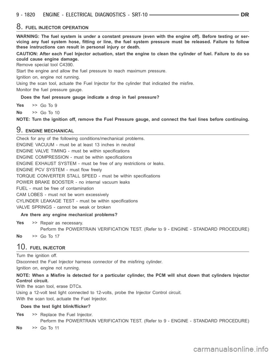
8.FUEL INJECTOR OPERATION
WARNING: The fuel system is under a constant pressure (even with the engineoff). Before testing or ser-
vicing any fuel system hose, fitting or line, the fuel system pressure mustbe released. Failure to follow
these instructions can result in personal injury or death.
CAUTION: After each Fuel Injector actuation, start the engine to clean thecylinder of fuel. Failure to do so
could cause engine damage.
Remove special tool C4390.
Start the engine and allow the fuel pressure to reach maximum pressure.
Ignition on, engine not running.
Using the scan tool, actuate the Fuel Injector for the cylinder that indicated the misfire.
Monitor the fuel pressure gauge.
Does the fuel pressure gauge indicate a drop in fuel pressure?
Ye s>>
Go To 9
No>>
Go To 10
NOTE: Turn the ignition off, remove the Fuel Pressure gauge, and connect the fuel lines before continuing.
9.ENGINE MECHANICAL
Check for any of the following conditions/mechanical problems.
ENGINE VACUUM - must be at least 13 inches in neutral
ENGINE VALVE TIMING - must be within specifications
ENGINE COMPRESSION - must be within specifications
ENGINE EXHAUST SYSTEM - must be free of any restrictions or leaks.
ENGINE PCV SYSTEM - must flow freely
TORQUE CONVERTER STALL SPEED - must be within specifications
POWER BRAKE BOOSTER - no internal vacuum leaks
FUEL - must be free of contamination
CAM LOBES - must not be worn excessively
CYLINDER LEAKAGE TEST - must be within specifications
VALVE SPRINGS - cannot be weak or broken
Are there any engine mechanical problems?
Ye s>>
Repair as necessary.
Perform the POWERTRAIN VERIFICATION TEST. (Refer to 9 - ENGINE - STANDARD PROCEDURE)
No>>
Go To 17
10.FUEL INJECTOR
Turn the ignition off.
Disconnect the Fuel Injector harness connector of the misfiring cylinder.
Ignition on, engine not running.
NOTE: When a Misfire is detected for a particular cylinder, the PCM will shut down that cylinders Injector
Control circuit.
With the scan tool, erase DTCs.
Using a 12-volt test light connected to 12-volts, probe the Injector Control circuit.
With the scan tool, actuate the Fuel Injector.
Does the test light blink/flicker?
Ye s>>
Replace the Fuel Injector.
Perform the POWERTRAIN VERIFICATION TEST. (Refer to 9 - ENGINE - STANDARD PROCEDURE)
No>>
Go To 11
Page 1463 of 5267
Possible Causes
(A103) FUSED B+ CIRCUIT
(Z429) BRAKE LAMP SWITCH GROUND CIRCUIT OPEN
BRAKE LAMP SWITCH
(B29) BRAKE SWITCH NO.1 SIGNAL CIRCUIT OPEN
(B29) BRAKE SWITCH NO.1 SIGNAL CIRCUIT SHORT TO GROUND
PCM
Always perform the Pre-Diagnostic Troubleshooting procedure before proceeding. (Refer to 9 - ENGINE -
DIAGNOSIS AND TESTING)
Diagnostic Test
1.SCAN TOOL DOES NOT SHOW BRAKE SW PRESSED OR RELEASED
Ignition on, engine not running.
With the scan tool in Inputs/Outputs, read the Brake Switch state.
While observing the scan tool display, press and release the brake pedal several times.
Does the scan tool display Brake Switch PRESSED and RELEASED?
Ye s>>
The Brake Lamp Switch is operating properly at this time.
Perform the POWERTRAIN VERIFICATION TEST. (Refer to 9 - ENGINE - STANDARD PROCEDURE)
No>>
Go To 2
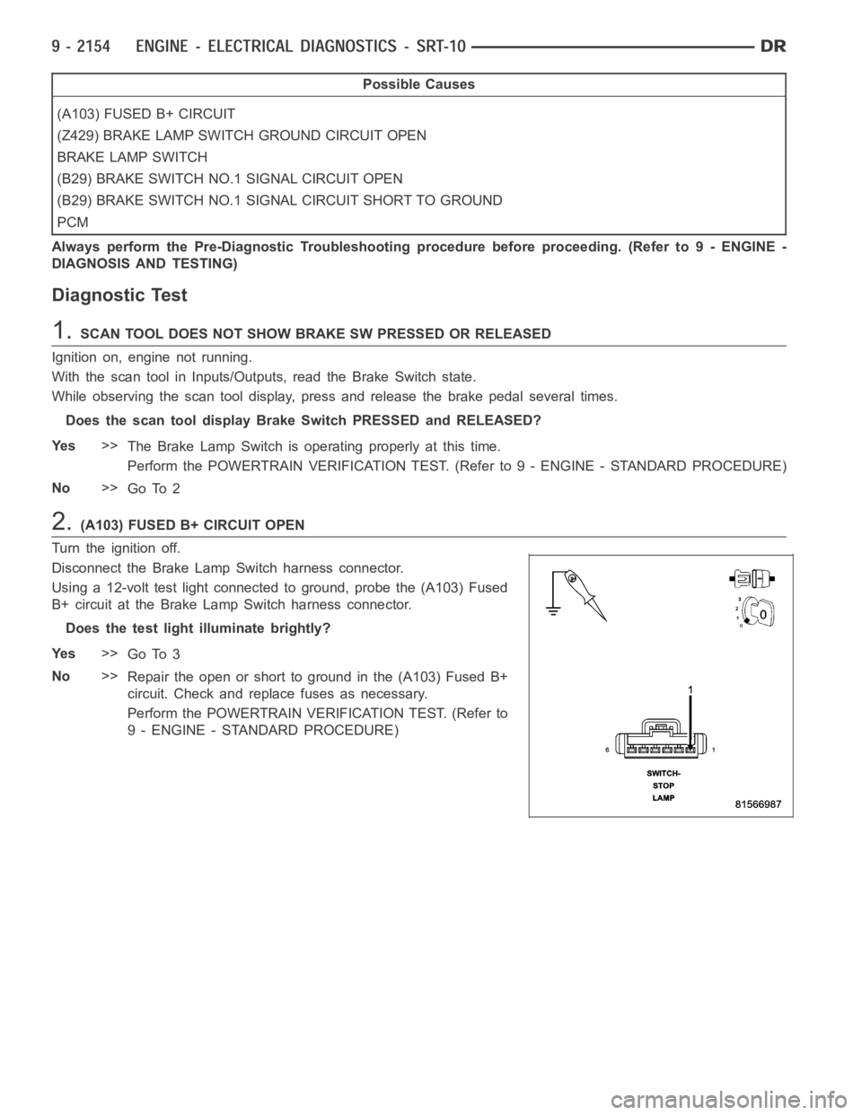
2.(A103) FUSED B+ CIRCUIT OPEN
Turn the ignition off.
Disconnect the Brake Lamp Switch harness connector.
Using a 12-volt test light connected to ground, probe the (A103) Fused
B+ circuit at the Brake Lamp Switch harness connector.
Does the test light illuminate brightly?
Ye s>>
Go To 3
No>>
Repair the open or short to ground in the (A103) Fused B+
circuit. Check and replace fuses as necessary.
Perform the POWERTRAIN VERIFICATION TEST. (Refer to
9 - ENGINE - STANDARD PROCEDURE)
Page 1464 of 5267
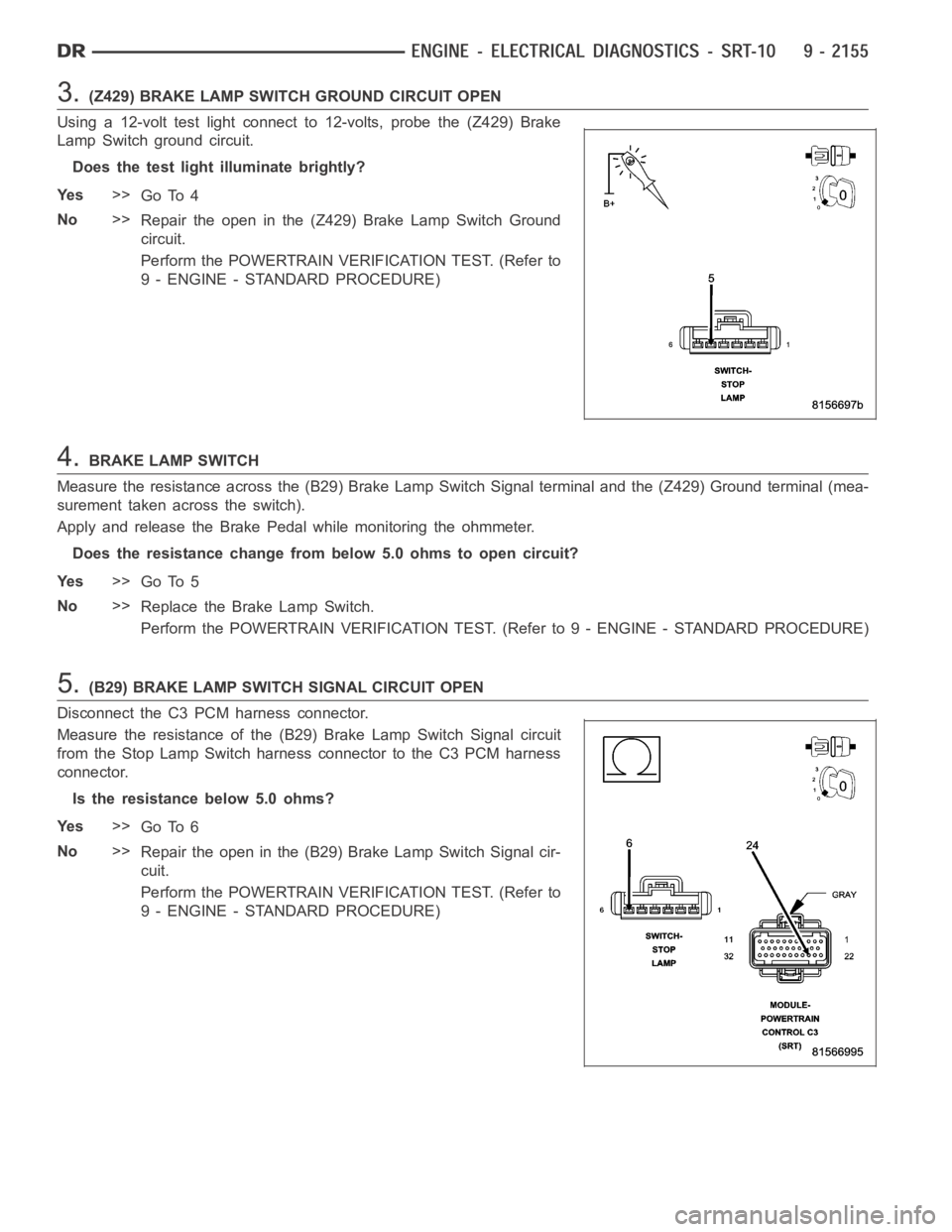
3.(Z429) BRAKE LAMP SWITCH GROUND CIRCUIT OPEN
Using a 12-volt test light connect to 12-volts, probe the (Z429) Brake
Lamp Switch ground circuit.
Does the test light illuminate brightly?
Ye s>>
Go To 4
No>>
Repair the open in the (Z429) Brake Lamp Switch Ground
circuit.
Perform the POWERTRAIN VERIFICATION TEST. (Refer to
9 - ENGINE - STANDARD PROCEDURE)
4.BRAKE LAMP SWITCH
Measure the resistance across the (B29) Brake Lamp Switch Signal terminaland the (Z429) Ground terminal (mea-
surement taken across the switch).
Apply and release the Brake Pedal while monitoring the ohmmeter.
Does the resistance change frombelow 5.0 ohms to open circuit?
Ye s>>
Go To 5
No>>
Replace the Brake Lamp Switch.
Perform the POWERTRAIN VERIFICATION TEST. (Refer to 9 - ENGINE - STANDARD PROCEDURE)
5.(B29) BRAKE LAMP SWITCH SIGNAL CIRCUIT OPEN
Disconnect the C3 PCM harness connector.
Measure the resistance of the (B29) Brake Lamp Switch Signal circuit
from the Stop Lamp Switch harness connector to the C3 PCM harness
connector.
Is the resistance below 5.0 ohms?
Ye s>>
Go To 6
No>>
Repair the open in the (B29) Brake Lamp Switch Signal cir-
cuit.
Perform the POWERTRAIN VERIFICATION TEST. (Refer to
9 - ENGINE - STANDARD PROCEDURE)
Page 1465 of 5267
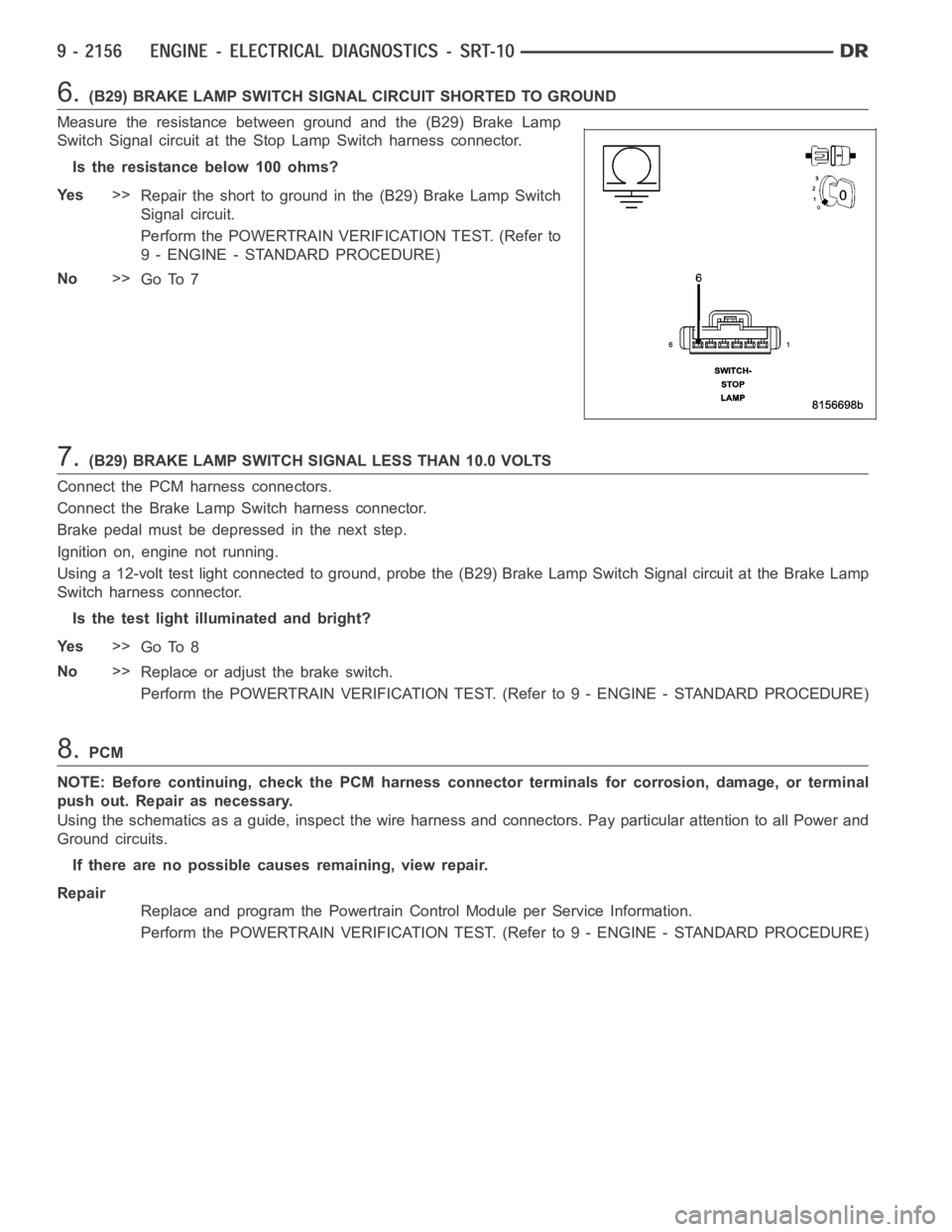
6.(B29) BRAKE LAMP SWITCH SIGNAL CIRCUIT SHORTED TO GROUND
Measure the resistance between ground and the (B29) Brake Lamp
Switch Signal circuit at the Stop Lamp Switch harness connector.
Istheresistancebelow100ohms?
Ye s>>
Repair the short to ground in the (B29) Brake Lamp Switch
Signal circuit.
Perform the POWERTRAIN VERIFICATION TEST. (Refer to
9 - ENGINE - STANDARD PROCEDURE)
No>>
Go To 7
7.(B29) BRAKE LAMP SWITCH SIGNAL LESS THAN 10.0 VOLTS
Connect the PCM harness connectors.
Connect the Brake Lamp Switch harness connector.
Brake pedal must be depressed in the next step.
Ignition on, engine not running.
Using a 12-volt test light connected to ground, probe the (B29) Brake Lamp Switch Signal circuit at the Brake Lamp
Switch harness connector.
Is the test light illuminated and bright?
Ye s>>
Go To 8
No>>
Replace or adjust the brake switch.
Perform the POWERTRAIN VERIFICATION TEST. (Refer to 9 - ENGINE - STANDARD PROCEDURE)
8.PCM
NOTE: Before continuing, check the PCM harness connector terminals for corrosion, damage, or terminal
push out. Repair as necessary.
Using the schematics as a guide, inspect the wire harness and connectors. Pay particular attention to all Power and
Ground circuits.
If there are no possible causes remaining, view repair.
Repair
Replace and program the Powertrain Control Module per Service Information.
Perform the POWERTRAIN VERIFICATION TEST. (Refer to 9 - ENGINE - STANDARD PROCEDURE)
Page 1483 of 5267
POWERTRAIN VERIFICATION TEST
For a complete wiring diagramRefer to Section 8W.
Diagnostic Test
1.SELECTING THE PROPER VERIFICATION TEST
The following verification test are for different repairs. Select the appropriate Verification test for the
repair that has been completed.
Speed Control repair
Go To 2
Charging System repair
Go To 3
NVLD System repair
Go To 4
All other repairs
Go To 5
2.POWERTRAIN VERIFICATION TEST 1
NOTE: 1. If this vehicle is equipped with an Electronic Throttle Control system, and the APP Sensors, PCM,
or Throttle Body Assembly have been replaced, use the scan tool to perform the ETC RELEARN function.
NOTE: 2. After completing the Powertrain Verification Test the Transmission Verification Test must be per-
formed.
NOTE: 3. If the PCM has been replaced and the correct VIN and mileage have notbeen programmed, a DTC
will set in the ABS Module, Airbag Module and the SKIM/SKREEM.
NOTE: 4. If the vehicle is equipped with a Sentry Key Remote Entry, Secret Key data must be updated. Refer
to the Service Information for the PCM, SKIM/SKREEM and the Transponder (ignition key) for programming
information. Using the scan tool, program the Secret Key information intothe PCM using the PCM replaced
function under the WCM menu.
5. Inspect the vehicle to make sure that all engine components are properlyinstalled and connected.
6. Connect the scan tool to the data link connector and erase all codes.
7. Turn the speed control ON (if equipped, cruise light will be on).
8. Depress and release the SET Switch when the vehicle speed is greater than35 MPH. The speed control should
engage and hold the selected speed.
9. Press and hold the RESUME/ACCEL Switch. The vehicle speed should increase by at least 2 MPH.
10. Press and hold the COAST switch. The vehicle speed should decrease.
11. Using caution, press and release the brake pedal. The speed control should disengage.
12. Bring the vehicle speed back up to 35 MPH.
13. Press the RESUME/ACCEL switch. The speed control should resume the previously set speed.
14. Hold down the SET switch. The vehicle should decelerate.
15. Make sure vehicle speed is greater than 35 mph and release the SET Switch. The vehicle should adjust and set
a new vehicle speed.
16. Press and release the CANCEL switch. The speed control should disengage.
17. Bring the vehicle speed back up above 35 mph and engage speed control.
18. Turn the Speed Control Off. (Cruise light will be off). The speed control should disengage.
NOTE: OVERSHOOT/UNDERSHOOT FOLLOWING SPEED CONTROL SET.
19. If the vehicle operator repeatedly presses and releases the SET buttonwith their foot off of the accelerator
(referred to as
lift foot set), the vehicle may accelerate and exceed the desired set speed by up to 5 mph (8km/h).
20. It may also decelerate to less than the desired set speed, before finally achieving the desired set speed.
21. The Speed Control System has an adaptive strategy that compensates forvehicle-to-vehicle variations in speed
control cable lengths.
22. When the speed control is set with the vehicles operators foot off of theaccelerator pedal, the speed control
thinks there is excessive speed control cable slack and adapts accordingly.
Page 2104 of 5267
BLOCK-ENGINE
DESCRIPTION
The cylinder block is made of a sand-cast aluminum alloy. The cylinder block has interference-fit cast iron cylinder
liners. The cylinder liners are thermally installed during block manufacturing; they are not serviceable items.
Six iron main bearing caps use four bolts per cap; two vertical and two horizontal. A crankshaft oil scraper is
attached to the main bearing caps via extended main bearing cap bolts and nuts.
STANDARD PROCEDURE - CYLINDER BORE HONING
Before honing, stuff plenty of clean shop towels under
the bores and over the crankshaft to keep abrasive
materials from entering the crankshaft area.
1. Used carefully, the Cylinder Bore Sizing Hone
C-823, equipped with 220 grit stones, is the best
tool for this job. In addition to deglazing, it will
reduce taper and out-of-round, as well as removing
light scuffing, scoring and scratches. Usually, a few
strokes will clean up a bore and maintain the
required limits.
CAUTION: DO NOT use rigid type hones to remove
cylinder wall glaze.
2. Deglazing of the cylinder walls may be done if the
cylinder bore is straight and round. Use a cylinder
surfacing hone, Honing Tool C-3501, equipped with
280 grit stones (C-3501-3810). about 20-60
strokes, depending on the bore condition, will be
sufficient to provide a satisfactory surface. Using
honing oil C-3501-3880, or a light honing oil, avail-
able from major oil distributors.
CAUTION: DO NOT use engine or transmission oil, mineral spirits, or kerosene.
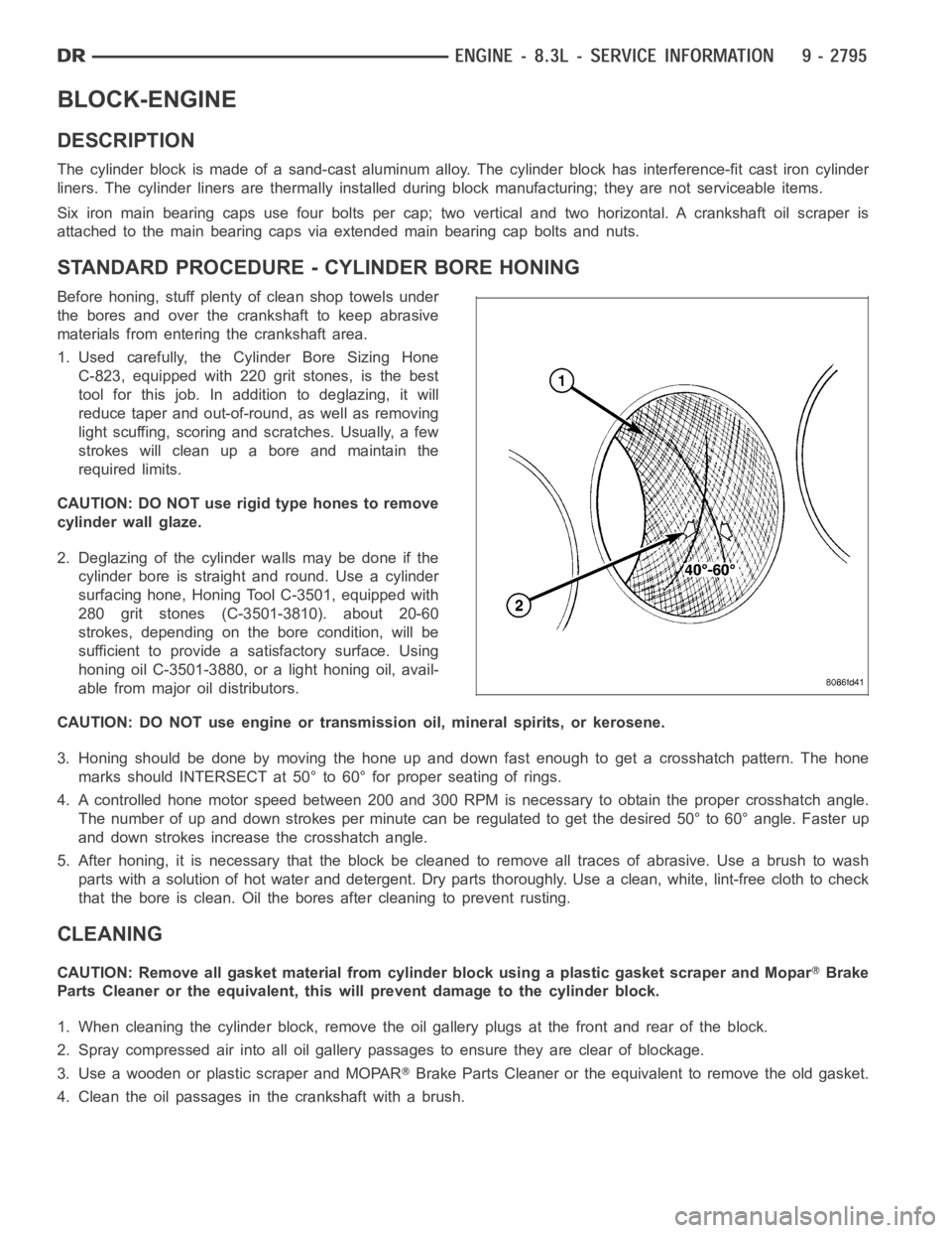
3. Honing should be done by moving the hone up and down fast enough to get a crosshatch pattern. The hone
marks should INTERSECT at 50° to 60° for proper seating of rings.
4. A controlled hone motor speed between 200 and 300 RPM is necessary to obtain the proper crosshatch angle.
The number of up and down strokes per minute can be regulated to get the desired 50° to 60° angle. Faster up
and down strokes increase the crosshatch angle.
5. After honing, it is necessary that the block be cleaned to remove all traces of abrasive. Use a brush to wash
parts with a solution of hot water and detergent. Dry parts thoroughly. Usea clean, white, lint-free cloth to check
that the bore is clean. Oil the bores after cleaning to prevent rusting.
CLEANING
CAUTION: Remove all gasket material from cylinder block using a plastic gasket scraper and MoparBrake
Parts Cleaner or the equivalent, this will prevent damage to the cylinder block.
1. When cleaning the cylinder block, remove the oil gallery plugs at the front and rear of the block.
2. Spray compressed air into all oil gallery passages to ensure they are clear of blockage.
3. Use a wooden or plastic scraper and MOPAR
Brake Parts Cleaner or the equivalent to remove the old gasket.
4. Clean the oil passages in the crankshaft with a brush.
Page 2358 of 5267
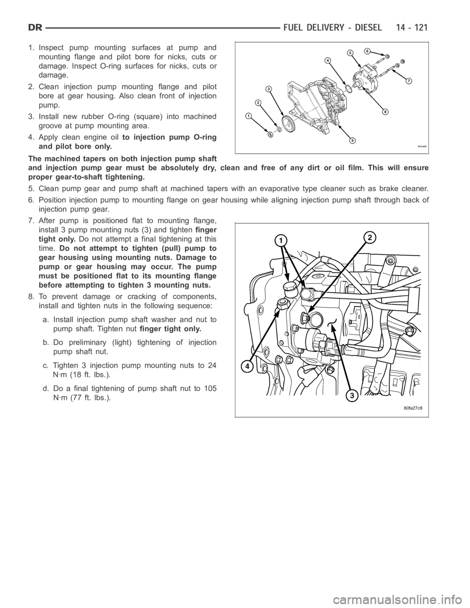
1. Inspect pump mounting surfaces at pump and
mounting flange and pilot bore for nicks, cuts or
damage. Inspect O-ring surfaces for nicks, cuts or
damage.
2. Clean injection pump mounting flange and pilot
bore at gear housing. Also clean front of injection
pump.
3. Install new rubber O-ring (square) into machined
groove at pump mounting area.
4. Apply clean engine oilto injection pump O-ring
and pilot bore only.
The machined tapers on both injection pump shaft
and injection pump gear must be absolutely dry, clean and free of any dirt oroil film. This will ensure
proper gear-to-shaft tightening.
5. Clean pump gear and pump shaft at machined tapers with an evaporative type cleaner such as brake cleaner.
6. Position injection pump to mounting flange on gear housing while aligning injection pump shaft through back of
injection pump gear.
7. After pump is positioned flat to mounting flange,
install 3 pump mounting nuts (3) and tightenfinger
tight only.Do not attempt a final tightening at this
time.Do not attempt to tighten (pull) pump to
gear housing using mounting nuts. Damage to
pump or gear housing may occur. The pump
must be positioned flat to its mounting flange
before attempting to tighten 3 mounting nuts.
8. To prevent damage or cracking of components,
install and tighten nuts in the following sequence:
a. Install injection pump shaft washer and nut to
pump shaft. Tighten nutfinger tight only.
b. Do preliminary (light) tightening of injection
pump shaft nut.
c. Tighten 3 injection pump mounting nuts to 24
Nꞏm (18 ft. lbs.).
d. Do a final tightening of pump shaft nut to 105
Nꞏm (77 ft. lbs.).
Page 2416 of 5267
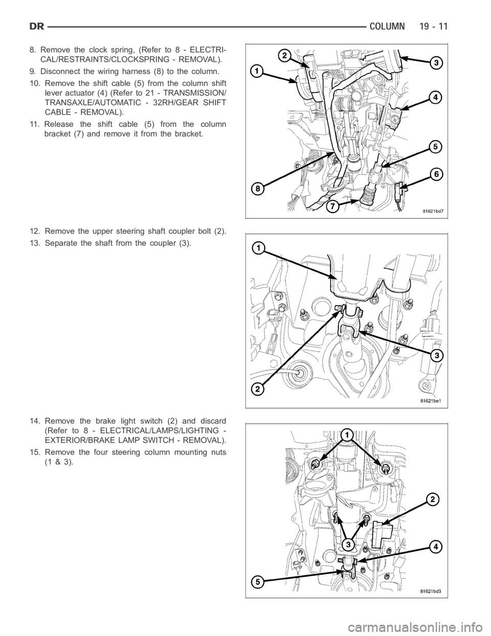
8. Remove the clock spring, (Refer to 8 - ELECTRI-
CAL/RESTRAINTS/CLOCKSPRING - REMOVAL).
9. Disconnect the wiring harness (8) to the column.
10. Remove the shift cable (5) from the column shift
lever actuator (4) (Refer to 21 - TRANSMISSION/
TRANSAXLE/AUTOMATIC - 32RH/GEAR SHIFT
CABLE - REMOVAL).
11. Release the shift cable (5) from the column
bracket (7) and remove it from the bracket.
12. Remove the upper steering shaft coupler bolt (2).
13. Separate the shaft from the coupler (3).
14. Remove the brake light switch (2) and discard
(Refer to 8 - ELECTRICAL/LAMPS/LIGHTING -
EXTERIOR/BRAKE LAMP SWITCH - REMOVAL).
15. Remove the four steering column mounting nuts
(1 & 3).