stop start DODGE RAM SRT-10 2006 Service User Guide
[x] Cancel search | Manufacturer: DODGE, Model Year: 2006, Model line: RAM SRT-10, Model: DODGE RAM SRT-10 2006Pages: 5267, PDF Size: 68.7 MB
Page 1063 of 5267
NOTE: Short Term Adaptive value change.
Did the Short Term Adaptive value change?
Ye s>>
Go To 6
No>>
Refer to the Driveability category and perform the appropriate Diagnostictest.
Perform the POWERTRAIN VERIFICATION TEST. (Refer to 9 - ENGINE - STANDARD PROCEDURE)
6.TP SENSOR VOLTAGE GREATER THAN 0.92 OF A VOLT WITH THROTTLE CLOSED
Ignition on, engine not running.
With the scan tool, read TP Sensor voltage.
NOTE: The throttle must be against the stop.
Isthevoltage0.92ofavoltorlesswiththeThrottleclosed?
Ye s>>
Go To 7
No>>
Check for a binding throttle condition. If OK, replace the Throttle Position Sensor.
Perform the POWERTRAIN VERIFICATION TEST. (Refer to 9 - ENGINE - STANDARD PROCEDURE)
7.TP SENSOR SWEEP
With the scan tool, read the TP Sensor voltage.
While monitoring the scan tool, slowly open and close the throttle.
Does the voltage increase and decrease smoothly?
Ye s>>
Go To 8
No>>
ReplacetheThrottlePositionSensor.
Perform the POWERTRAIN VERIFICATION TEST. (Refer to 9 - ENGINE - STANDARD PROCEDURE)
8.MAP SENSOR OPERATION
Turn the ignition off.
Connect a Vacuum Gauge to a Manifold Vacuum source.
Start the engine.
Allow the engine to idle.
NOTE: If engine will not idle, maintain a constant RPM above idle.
With the scan tool in Sensors, read the MAP Sensor vacuum value.
Is the scan tool reading within 1
of the Vacuum Gauge reading?
Ye s>>
Go To 9
No>>
Replace the MAP Sensor.
Perform the POWERTRAIN VERIFICATION TEST. (Refer to 9 - ENGINE - STANDARD PROCEDURE)
NOTE: Remove the vacuum gauge before continuing.
Page 1075 of 5267
2.CHECKING FUEL PRESSURE
Turn the ignition off.
WARNING: The fuel system is under a constant pressure (even with the engineoff). Before testing or ser-
vicing any fuel system hose, fitting or line, the fuel system pressure mustbe released.
Install a fuel pressure gauge.
Ignition on, engine not running.
With the scan tool, actuate the ASD FuelSystem test and observe the fuel pressure gauge.
NOTE: Fuel pressure specification is 379 KPa +/- 14 KPa (55 psi +/- 2 psi).
Choose a conclusion that best matches your fuel pressure reading.
Within Specification
Go To 3
Above Specification
Replace the fuel filter/pressure regulator.
Perform the POWERTRAIN VERIFICATION TEST. (Refer to 9 - ENGINE - STANDARD PROCEDURE)
CAUTION: Stop All Actuations.
3.O2 SENSOR OPERATION
Ignition on, engine not running.
With the scan tool, monitor all of the O2 Sensor voltage readings.
Is the voltage above 4.5 volts for all of the O2 Sensors?
Ye s>>
Go To 4
No>>
Go To 11
4.O2 SENSOR HEATER OPERATION
Turn the ignition off.
NOTE: Wait a minimum of 10 minutes to allow the O2 Sensor to cool down before continuing the test. Allow
the O2 Sensor voltage to stabilize between 4 and 5 volts.
Ignition on, engine not running.
With the scan tool, actuate the O2 Heater Test.
With the scan tool, monitor O2 Sensor voltage for at least 2 minutes.
Does the voltage stay above 4.5 volts?
Ye s>>
Replace the O2 Sensor that had the voltage reading above 4.5 volts.
Perform the POWERTRAIN VERIFICATION TEST. (Refer to 9 - ENGINE - STANDARD PROCEDURE)
No>>
Go To 5
5.EVAP SYSTEM OPERATION
NOTE: The engine must be at operating temperature and in closed loop to perform this test.
Start the engine.
WARNING: When the engine is operating, do not stand in a direct line with thefan. Do not put your hands
near the pulleys, belts, or fan. Do not wear loose clothing.
Allow the engine to reach normal operating temperature.
With the scan tool select System Tests, perform the Purge Vapors Test.
Observe the Short Term Adaptive value and press 3 to flow.
Page 1076 of 5267
NOTE: Short Term Adaptive value change.
Did the Short Term Adaptive value change?
Ye s>>
Go To 6
No>>
Refer to the Driveability category and perform the appropriate Diagnostictest.
Perform the POWERTRAIN VERIFICATION TEST. (Refer to 9 - ENGINE - STANDARD PROCEDURE)
6.TP SENSOR VOLTAGE GREATER THAN 0.92 OF A VOLT WITH THROTTLE CLOSED
Ignition on, engine not running.
With the scan tool, read TP Sensor voltage.
NOTE: The throttle must be against the stop.
Isthevoltage0.92ofavoltorlesswiththeThrottleclosed?
Ye s>>
Go To 7
No>>
Check for a binding throttle condition. If OK, replace the Throttle Position Sensor.
Perform the POWERTRAIN VERIFICATION TEST. (Refer to 9 - ENGINE - STANDARD PROCEDURE)
7.TP SENSOR SWEEP
With the scan tool, read the TP Sensor voltage.
While monitoring the scan tool, slowly open and close the throttle.
Does the voltage increase and decrease smoothly?
Ye s>>
Go To 8
No>>
ReplacetheThrottlePositionSensor.
Perform the POWERTRAIN VERIFICATION TEST. (Refer to 9 - ENGINE - STANDARD PROCEDURE)
8.MAP SENSOR OPERATION
Turn the ignition off.
Connect a Vacuum Gauge to a Manifold Vacuum source.
Start the engine.
Allow the engine to idle.
NOTE: If engine will not idle, maintain a constant RPM above idle.
With the scan tool in Sensors, read the MAP Sensor vacuum value.
Is the scan tool reading within 1
of the Vacuum Gauge reading?
Ye s>>
Go To 9
No>>
Replace the MAP Sensor.
Perform the POWERTRAIN VERIFICATION TEST. (Refer to 9 - ENGINE - STANDARD PROCEDURE)
NOTE: Remove the vacuum gauge before continuing.
Page 1587 of 5267
DIAGNOSIS AND TESTING
DIAGNOSIS AND TESTING - ENGINE OIL LEAK
Begin with a thorough visual inspection of the engine, particularly at thearea of the suspected leak. If an oil leak
source is not readily identifiable, thefollowingstepsshouldbefollowed:
1. Do not clean or degrease the engine at this time because some solvents maycause rubber to swell, temporarily
stopping the leak.
2. Add an oil soluble dye (use as recommended by manufacturer). Start the engine and let idle for approximately 15
minutes. Check the oil dipstick to make sure the dye is thoroughly mixed as indicated with a bright yellow color
under a black light.
3. Using a black light, inspect the entire engine for fluorescent dye, particularly at the suspected area of oil leak. If
the oil leak is found and identified, repair per service manual instructions.
4. If dye is not observed, drive the vehicle at various speeds for approximately 24 km (15 miles), and repeat inspec-
tion.If the oil leak source is not positively identified at this time, proceed with the air leak detection test method.
Air Leak Detection Test Method
1. Disconnect the breather cap to air cleaner hose at the breather cap end. Cap or plug breather cap nipple.
2. Remove the PCV valve from the cylinder head cover. Cap or plug the PCV valvegrommet.
3. Attach an air hose with pressure gauge and regulator to the dipstick tube.
CAUTION: Do not subject the engine assembly to more than 20.6 kPa (3 PSI) of test pressure.
4. Gradually apply air pressure from 1 psi to 2.5 psi maximum while applyingsoapy water at the suspected source.
Adjust the regulator to the suitable test pressure that provide the best bubbles which will pinpoint the leak
source. If the oil leak is detected and identified, repair per service manual procedures.
5. If the leakage occurs at the rear oil seal area, refer to the section, Inspection for Rear Seal Area Leak.
6. If no leaks are detected, turn off the air supply and remove the air hose and all plugs and caps. Install the PCV
valve and breather cap hose.
7. Clean the oil off the suspect oil leak area using a suitable solvent. Drive the vehicle at various speeds approx-
imately 24 km (15 miles). Inspect the engine for signs of an oil leak by usinga black light.
INSPECTION FOR REAR SEAL AREA LEAKS
Since it is sometimes difficult to determine the source of an oil leak in therear seal area of the engine, a more
involved inspection is necessary. The following steps should be followedto help pinpoint the source of the leak.
If the leakage occurs at the crankshaft rear oil seal area:
1. Disconnect the battery.
2. Raise the vehicle.
3. Remove torque converter or clutch housing cover and inspect rear of block for evidence of oil. Use a black light
to check for the oil leak:
a. Circular spray pattern generally indicates seal leakage or crankshaftdamage.
b. Where leakage tends to run straight down, possible causes are a porous block, oil galley pipe plugs, oil filter
runoff, and main bearing cap to cylinder block mating surfaces.
4. If no leaks are detected, pressurize the crankcase as outlined in the, Inspection (Engine oil Leaks in general)
CAUTION: Do not exceed 20.6 kPa (3 psi).
5. If the leak is not detected, very slowly turn the crankshaft and watch forleakage. If a leak is detected between
the crankshaft and seal while slowly turning the crankshaft, it is possible the crankshaft seal surface is damaged.
The seal area on the crankshaft could have minor nicks or scratches that canbe polished out with emery cloth.
CAUTION: Use extreme caution when crankshaft polishing is necessary to remove minor nicks and
scratches. The crankshaft seal flange is especially machined to complement the function of the rear oil seal.
6. For bubbles that remain steady with shaft rotation, no further inspection can be done until disassembled.
Page 1722 of 5267
DIAGNOSIS AND TESTING - ENGINE OIL LEAK
Begin with a thorough visual inspection of the engine, particularly at thearea of the suspected leak. If an oil leak
source is not readily identifiable, thefollowingstepsshouldbefollowed:
1. Do not clean or degrease the engine at this time because some solvents maycause rubber to swell, temporarily
stopping the leak.
2. Add an oil soluble dye (use as recommended by manufacturer). Start the engine and let idle for approximately 15
minutes. Check the oil dipstick to make sure the dye is thoroughly mixed as indicated with a bright yellow color
under a black light.
3. Using a black light, inspect the entire engine for fluorescent dye, particularly at the suspected area of oil leak. If
the oil leak is found and identified, repair per service manual instructions.
4. If dye is not observed, drive the vehicle at various speeds for approximately 24 km (15 miles), and repeat inspec-
tion.If the oil leak source is not positively identified at this time, proceed with the air leak detection test method.
Air Leak Detection Test Method
1. Disconnect the breather cap to air cleaner hose at the breather cap end. Cap or plug breather cap nipple.
2. Remove the PCV valve from the cylinder head cover. Cap or plug the PCV valvegrommet.
3. Attach an air hose with pressure gauge and regulator to the dipstick tube.
CAUTION: Do not subject the engine assembly to more than 20.6 kPa (3 PSI) of test pressure.
4. Gradually apply air pressure from 1 psi to 2.5 psi maximum while applyingsoapy water at the suspected source.
Adjust the regulator to the suitable test pressure that provide the best bubbles which will pinpoint the leak
source. If the oil leak is detected and identified, repair per service manual procedures.
5. If the leakage occurs at the rear oil seal area, refer to the section, Inspection for Rear Seal Area Leak.
6. If no leaks are detected, turn off the air supply and remove the air hose and all plugs and caps. Install the PCV
valve and breather cap hose.
7. Clean the oil off the suspect oil leak area using a suitable solvent. Drive the vehicle at various speeds approx-
imately 24 km (15 miles). Inspect the engine for signs of an oil leak by usinga black light.
INSPECTION FOR REAR SEAL AREA LEAKS
Since it is sometimes difficult to determine the source of an oil leak in therear seal area of the engine, a more
involved inspection is necessary. The following steps should be followedto help pinpoint the source of the leak.
If the leakage occurs at the crankshaft rear oil seal area:
1. Disconnect the battery.
2. Raise the vehicle.
3. Remove torque converter or clutch housing cover and inspect rear of block for evidence of oil. Use a black light
to check for the oil leak:
a. Circular spray pattern generally indicates seal leakage or crankshaftdamage.
b. Where leakage tends to run straight down, possible causes are a porous block, oil galley pipe plugs, oil filter
runoff, and main bearing cap to cylinder block mating surfaces.
4. If no leaks are detected, pressurize the crankcase as outlined in the, Inspection (Engine oil Leaks in general)
CAUTION: Do not exceed 20.6 kPa (3 psi).
5. If the leak is not detected, very slowly turn the crankshaft and watch forleakage. If a leak is detected between
the crankshaft and seal while slowly turning the crankshaft, it is possible the crankshaft seal surface is damaged.
The seal area on the crankshaft could have minor nicks or scratches that canbe polished out with emery cloth.
CAUTION: Use extreme caution when crankshaft polishing is necessary to remove minor nicks and
scratches. The crankshaft seal flange is especially machined to complement the function of the rear oil seal.
6. For bubbles that remain steady with shaft rotation, no further inspection can be done until disassembled.
Page 1875 of 5267
LUBRICATION
DIAGNOSIS AND TESTING
DIAGNOSIS AND TESTING - CHECKING ENGINE OIL PRESSURE
1. Remove oil pressure sending unit and install gauge assembly C-3292.
2. Run engine until thermostat opens.
3. Oil Pressure:
Curb Idle–25 kPa (4 psi) minimum
3000 rpm–170 - 758 kPa (25 - 110 psi)
4. If oil pressure is 0 at idle, shut off engine. Check for a clogged oil pick-up screen or a pressure relief valve stuck
open.
DIAGNOSIS AND TESTING - ENGINE OIL LEAK
Begin with a thorough visual inspection of the engine, particularly at thearea of the suspected leak. If an oil leak
source is not readily identifiable, thefollowingstepsshouldbefollowed:
1. Do not clean or degrease the engine at this time because some solvents maycause rubber to swell, temporarily
stopping the leak.
2. Add an oil soluble dye (use as recommended by manufacturer). Start the engine and let idle for approximately 15
minutes. Check the oil dipstick to make sure the dye is thoroughly mixed as indicated with a bright yellow color
under a black light.
3. Using a black light, inspect the entire engine for fluorescent dye, particularly at the suspected area of oil leak. If
the oil leak is found and identified, repair per service manual instructions.
4. If dye is not observed, drive the vehicle at various speeds for approximately 24 km (15 miles), and repeat inspec-
tion.If the oil leak source is not positively identified at this time, proceed with the air leak detection test
method.
Air Leak Detection Test Method
1. Remove the PCV valve from the IAFM. Cap or plug the PCV valve grommet.
2. Attach an air hose with pressure gauge and regulator to the dipstick tube.
CAUTION: Do not subject the engine assembly to more than 20.6 kPa (3 PSI) of test pressure.
3. Gradually apply air pressure from 1 psi to 2.5 psi maximum while applyingsoapy water at the suspected source.
Adjust the regulator to the suitable test pressure that provide the best bubbles which will pinpoint the leak
source. If the oil leak is detected and identified, repair per service manual procedures.
4. If the leakage occurs at the rear oil seal area, refer to the section, Inspection for Rear Seal Area Leak.
5. If no leaks are detected, turn off the air supply and remove the air hose and all plugs and caps. Install the PCV
valve.
6. Clean the oil off the suspect oil leak area using a suitable solvent. Drive the vehicle at various speeds approx-
imately 24 km (15 miles). Inspect the engine for signs of an oil leak by usinga black light.
INSPECTION FOR REAR SEAL AREA LEAKS
Since it is sometimes difficult to determine the source of an oil leak in therear seal area of the engine, a more
involved inspection is necessary. The following steps should be followedto help pinpoint the source of the leak.
If the leakage occurs at the crankshaft rear oil seal area:
1. Disconnect the battery.
2. Raise the vehicle.
3. Remove torque converter or clutch housing cover and inspect rear of block for evidence of oil. Use a black light
to check for the oil leak:
a. Circular spray pattern generally indicates seal leakage or crankshaftdamage.
Page 1877 of 5267
OIL
STANDARD PROCEDURE - ENGINE OIL SERVICE
The engine oil level indicator is located at the left hand of the engine on the 5.7L engines.
CRANKCASE OIL LEVEL INSPECTION
CAUTION: Do not overfill crankcase with engine oil, pressure loss or oil foaming can result.
Inspect engine oil level approximately every 800 kilometers (500 miles).Unless the engine has exhibited loss of oil
pressure, run the engine for about ten minutes before checking oil level. Checking engine oil level on a cold engine
is not accurate.
To ensure proper lubrication of an engine, the engine oil must be maintained at an acceptable level. The acceptable
levels are indicated between the ADD and SAFE marks on the engine oil dipstick.
1. Position vehicle on level surface.
2. With engine OFF, allow approximately five minutes for oil to settle to bottom of crankcase, remove engine oil
dipstick.
3. Wipe dipstick clean.
4. Install dipstick and verify it is seated in the tube.
5. Remove dipstick, with handle held above the tip, take oil level reading.
6. Add oil only if level is below the ADD mark on dipstick.
ENGINE OIL CHANGE
Change engine oil at mileage and time intervals described in Maintenance Schedules (Refer to LUBRICATION &
MAINTENANCE/MAINTENANCESCHEDULES - DESCRIPTION).
Run engine until achieving normal operating temperature.
1. Position the vehicle on a level surface and turn engine off.
2. Hoist and support vehicle on safety stands.
3. Remove oil fill cap.
4. Place a suitable drain pan under crankcase drain.
5. Remove drain plug from crankcase and allow oil to drain into pan. Inspectdrain plug threads for stretching or
other damage. Replace drain plug if damaged.
6. Install drain plug in crankcase. Torque to 34 Nꞏm ( 25 ft. lbs.).
7. Lower vehicle and fill crankcase with specified type and amount of engine oil described in this section.
8. Install oil fill cap.
9. Start engine and inspect for leaks.
10. Stop engine and inspect oil level.
USED ENGINE OIL DISPOSAL
Care should be exercised when disposing used engine oil after it has been drained from a vehicle engine. Refer to
the WARNING at beginning of this section.
Page 2002 of 5267
OIL
STANDARD PROCEDURE
STANDARD PROCEDURE - ENGINE OIL LEVEL
CAUTION: Do not overfill crankcase with engine
oil, oil foaming and oil pressure loss can result.
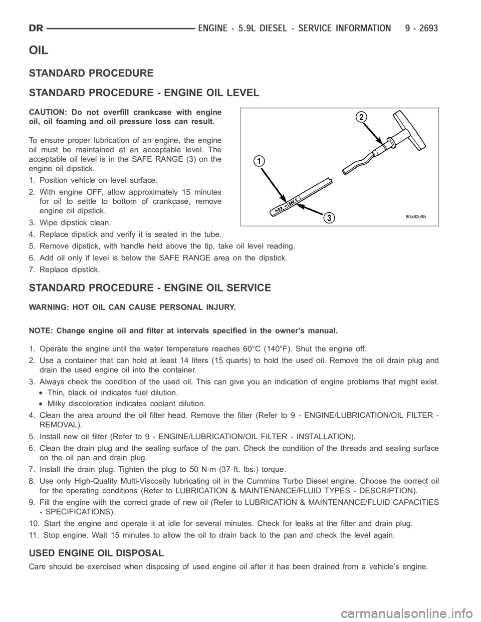
To ensure proper lubrication of an engine, the engine
oil must be maintained at an acceptable level. The
acceptable oil level is in the SAFE RANGE (3) on the
engine oil dipstick.
1. Position vehicle on level surface.
2. With engine OFF, allow approximately 15 minutes
for oil to settle to bottom of crankcase, remove
engine oil dipstick.
3. Wipe dipstick clean.
4. Replace dipstick and verify it is seated in the tube.
5. Remove dipstick, with handle held above the tip, take oil level reading.
6. Add oil only if level is below the SAFE RANGE area on the dipstick.
7. Replace dipstick.
STANDARD PROCEDURE - ENGINE OIL SERVICE
WARNING: HOT OIL CAN CAUSE PERSONAL INJURY.
NOTE: Change engine oil and filter at intervals specified in the owner’s manual.
1. Operate the engine until the water temperature reaches 60°C (140°F). Shut the engine off.
2. Use a container that can hold at least 14 liters (15 quarts) to hold the used oil. Remove the oil drain plug and
drain the used engine oil into the container.
3. Always check the condition of the used oil. This can give you an indication of engine problems that might exist.
Thin, black oil indicates fuel dilution.
Milky discoloration indicates coolant dilution.
4. Clean the area around the oil filter head. Remove the filter (Refer to 9 - ENGINE/LUBRICATION/OIL FILTER -
REMOVAL).
5. Install new oil filter (Refer to 9 - ENGINE/LUBRICATION/OIL FILTER - INSTA L L AT I O N ) .
6. Clean the drain plug and the sealing surface of the pan. Check the condition of the threads and sealing surface
on the oil pan and drain plug.
7. Install the drain plug. Tighten the plug to 50 Nꞏm (37 ft. lbs.) torque.
8. Use only High-Quality Multi-Viscosity lubricating oil in the Cummins Turbo Diesel engine. Choose the correct oil
for the operating conditions (Refer to LUBRICATION & MAINTENANCE/FLUID TYPES - DESCRIPTION).
9. Fill the engine with the correct grade of new oil (Refer to LUBRICATION & MAINTENANCE/FLUID CAPACITIES
- SPECIFICATIONS).
10. Start the engine and operate it at idle for several minutes. Check for leaks at the filter and drain plug.
11. Stop engine. Wait 15 minutes to allow the oil to drain back to the pan and check the level again.
USED ENGINE OIL DISPOSAL
Care should be exercised when disposing of used engine oil after it has beendrained from a vehicle’s engine.
Page 2005 of 5267
PA N - E N G I N E O I L
REMOVAL
1. Disconnect the battery negative cables.
2. Install engine support fixture # 8534.
3. Raise vehicle on hoist.
4. Disconnect starter cables from starter motor.
5. Remove transmission and transfer case (if equipped).
6. Remove flywheel or flexplate.
7. Remove starter motor (Refer to 8 - ELECTRICAL/STARTING/STARTER MOTOR -REMOVAL) and transmission
adapter plate assembly.
WARNING: HOT OIL CAN CAUSE PERSONAL INJURY.
8. Drain the engine oil (Refer to 9 - ENGINE/LUBRICATION/OIL - STANDARD PROCEDURE).
9. Install the oil pan drain plug if sealing surface is not damaged and tighten to 50 Nꞏm (37 ft. lbs.) torque.
10. Remove oil pan bolts, break the pan to block seal, and lower pan slightlyandremoveoilsuctiontubefasteners.
11. Remove oil pan and suction tube.
CLEANING
Remove all gasket material from the oil pan and cylinder block sealing surfaces. Extra effort may be required
around T-joint areas. Clean oil pan and flush suction tube with a suitable solvent.
INSPECTION
Inspect the oil pan, suction tube, and tube braces for cracks and damage. Replace any defective component.
Inspect the oil drain plug and drain hole threads. Inspect the oil pan sealing surface for straightness. Repair any
minor imperfections with a ball-peen hammer. Do not attempt to repair an oil pan by welding.
INSTALLATION
1. Fill the T-joint between the pan rail/gear housing and pan rail/rear seal retainer with sealant. Use MoparSilicone
Rubber Adhesive Sealant or equivalent.
2. Place suction tube in oil pan and guide them into place. Slide oil pan gasket into postion.Using a new tube to
block gasket, install and tighten the suction tube bolts by hand. Startingwith the oil pump inlet bolts, tighten the
bolts to 24 Nꞏm (18 ft. lbs.) torque. Tighten the remaining tube brace boltsto 43 Nꞏm (32 ft. lbs.) torque.
3. Starting in the center and working outward, tighten the oil pan bolts to 28Nꞏm(21ft.lbs.)torque.
4. Install the flywheel housing assembly with the starter motor attached and tighten bolts to 77 Nꞏm (57 ft. lbs.)
torque.
5. Connect starter motor cables.
NOTE: A new clamping ring must be used on early or late builds, automatic or manual. Do not reuse clamp-
ing ring.
6. Install the flywheel to crankshaft adapter. Torque to 137 Nꞏm (101 ft. lbs.).
7. Install transmission and transfer case (if equipped).
8. Lower vehicle.
9. Remove the engine support fixture # 8534.
10. Install battery negative cables.
11. Fill the crankcase with new engine oil.
12. Start engine and check for leaks. Stop engine, check oil level, and adjust, if necessary.
Page 2029 of 5267
CHEMICAL TEST METHOD
Combustion leaks into the cooling system can also be checked by using Bloc-Chek Kit C-3685-A or equivalent.
Perform test following the procedures supplied with the tool kit.
HYDRAULIC TAPPET NOISE DIAGNOSIS
PRELIMINARY STEP TO CHECKING THE HYDRAULIC TAPPETS
Before disassembling any part of the engine to correct tappet noise, checkengine oil level and oil pressure.
1. Check the engine oil level.
Oil Level Check: stop engine after reaching normal operating temperature
The oil level should never be above the FULL mark on dipstick, or below the ADD mark. Either of
these two conditions could be responsible for noisy tappets. Allow 5 minutes to stabilize oil level,
check dipstick.
2. Remove oil pressure sensor.
3. Install a reliable oil pressure gauge at oil pressure sensor location.
The oil pressure should be 206.8 - 551.6 kPa (30 - 80 psi) at 2000 rpm.
OIL LEVEL TOO HIGH
If oil level is above the FULL mark on dipstick, it is possible for the connecting rods to dip into the oil while engine
is running and create foam. Foam in oil pan would be fed to the hydraulic tappets by the oil pump causing them to
become soft and allow valves to seat noisily.
OIL LEVEL TOO LOW
Low oil level may allow pump to take in air which when fed to the tappets, causes them to become soft and allows
valves to seat noisily. Any leaks on intake side of pump through which air canbedrawnwillcreatethesametappet
action. Check the lubrication system from the intake strainer to the pump cover, including the relief valve retainer
cap. When tappet noise is due to aeration, it may be intermittent or constant, and usually more than one tappet will
be noisy. When oil level and leaks have been corrected, engine should be operated at fast idle to allow all of the air
inside of the tappets to be bled out.
VALVE TRAIN NOISE DIAGNOSIS
To determine source of valve train noise, operate engine at idle with cylinder head covers removed and listen for
source of the noise.
NOTE: Worn valve guides or cocked springs are sometimes mistaken for noisytappets. If such is the case,
noise may be dampened by applying side thrust on the valve spring. If noise is not appreciably reduced, it
can be assumed the noise is in the tappet. Inspect the rocker arm push rod sockets and push rod ends for
wear.
Valve tappet noise ranges from light noise to a heavy click. A light noise isusually caused by excessive leak-down
around the unit plunger which will necessitate replacing the tappet, or bythe plunger partially sticking in the tappet
body cylinder. A heavy click is caused either by a tappet check valve not seating, or by foreign particles becoming
wedged between the plunger and the tappet body causing the plunger to stickin the down position. This heavy click
will be accompanied by excessive clearance between the valve stem and rocker arm as valve closes. In either case,
tappet assembly should be removed and replaced.
ENGINE OIL LEAK INSPECTION
Begin with a thorough visual inspection of the engine, particularly at thearea of the suspected leak. If an oil leak
source is not readily identifiable, thefollowingstepsshouldbefollowed:
1. Do not clean or degrease the engine at this time because some solvents maycause rubber to swell, temporarily
stopping the leak.
2. Add an oil soluble dye (use as recommended by manufacturer). Start the engine and let idle for approximately 15
minutes. Check the oil dipstick to make sure the dye is thoroughly mixed as indicated with a bright yellow color
under a black light.