stop start DODGE RAM SRT-10 2006 Service Owner's Guide
[x] Cancel search | Manufacturer: DODGE, Model Year: 2006, Model line: RAM SRT-10, Model: DODGE RAM SRT-10 2006Pages: 5267, PDF Size: 68.7 MB
Page 2452 of 5267
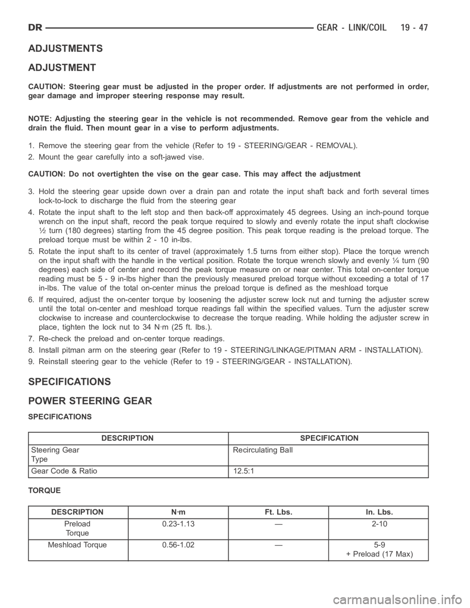
ADJUSTMENTS
ADJUSTMENT
CAUTION: Steering gear must be adjusted in the proper order. If adjustments are not performed in order,
gear damage and improper steering response may result.
NOTE: Adjusting the steering gear in the vehicle is not recommended. Remove gear from the vehicle and
drain the fluid. Then mount gear in a vise to perform adjustments.
1. Remove the steering gear from the vehicle(Referto19-STEERING/GEAR-REMOVAL).
2. Mount the gear carefully into a soft-jawed vise.
CAUTION: Do not overtighten the vise on the gear case. This may affect the adjustment
3. Hold the steering gear upside down over a drain pan and rotate the input shaft back and forth several times
lock-to-lock to discharge the fluid from the steering gear
4. Rotate the input shaft to the left stop and then back-off approximately 45 degrees. Using an inch-pound torque
wrench on the input shaft, record the peak torque required to slowly and evenly rotate the input shaft clockwise
1⁄2turn (180 degrees) starting from the 45 degree position. This peak torque reading is the preload torque. The
preload torque must be within 2 - 10 in-lbs.
5. Rotate the input shaft to its center of travel (approximately 1.5 turns from either stop). Place the torque wrench
on the input shaft with the handle in the vertical position. Rotate the torque wrench slowly and evenly
1⁄4turn (90
degrees) each side of center and record the peak torque measure on or near center. This total on-center torque
reading must be 5 - 9 in-lbs higher than the previously measured preload torque without exceeding a total of 17
in-lbs. The value of the total on-center minus the preload torque is defined as the meshload torque
6. If required, adjust the on-center torque by loosening the adjuster screw lock nut and turning the adjuster screw
until the total on-center and meshload torque readings fall within the specified values. Turn the adjuster screw
clockwise to increase and counterclockwise to decrease the torque reading. While holding the adjuster screw in
place, tighten the lock nut to 34 Nꞏm (25 ft. lbs.).
7. Re-check the preload and on-center torque readings.
8. Install pitman arm on the steering gear (Refer to 19 - STEERING/LINKAGE/PITMAN ARM - INSTALLATION).
9. Reinstall steering gear to the vehicle (Refer to 19 - STEERING/GEAR - INSTALLATION).
SPECIFICATIONS
POWER STEERING GEAR
SPECIFICATIONS
DESCRIPTION SPECIFICATION
Steering Gear
Ty peRecirculating Ball
Gear Code & Ratio 12.5:1
TORQUE
DESCRIPTION Nꞏm Ft. Lbs. In. Lbs.
Preload
To r q u e0.23-1.13 — 2-10
Meshload Torque 0.56-1.02 — 5-9
+ Preload (17 Max)
Page 2483 of 5267
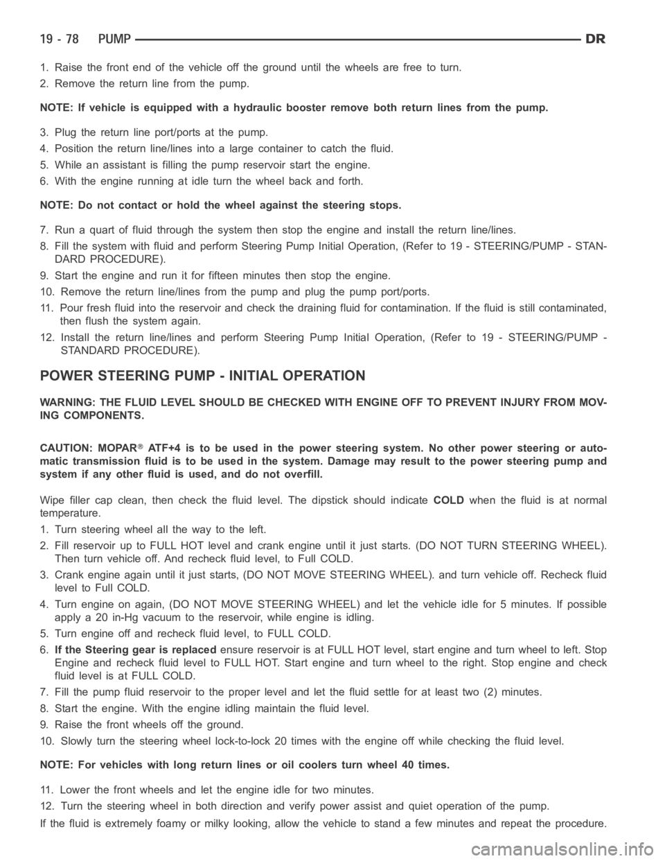
1. Raise the front end of the vehicle off the ground until the wheels are freeto turn.
2. Remove the return line from the pump.
NOTE: If vehicle is equipped with a hydraulic booster remove both return lines from the pump.
3. Plug the return line port/ports at the pump.
4. Position the return line/lines into a large container to catch the fluid.
5. While an assistant is filling the pump reservoir start the engine.
6. With the engine running at idle turn the wheel back and forth.
NOTE: Do not contact or hold the wheel against the steering stops.
7. Run a quart of fluid through the system then stop the engine and install the return line/lines.
8. Fill the system with fluid and perform Steering Pump Initial Operation,(Refer to 19 - STEERING/PUMP - STAN-
DARD PROCEDURE).
9. Start the engine and run it for fifteen minutes then stop the engine.
10. Remove the return line/lines from the pump and plug the pump port/ports.
11. Pour fresh fluid into the reservoir and check the draining fluid for contamination. If the fluid is still contaminated,
then flush the system again.
12. Install the return line/lines and perform Steering Pump Initial Operation, (Refer to 19 - STEERING/PUMP -
STANDARD PROCEDURE).
POWER STEERING PUMP - INITIAL OPERATION
WARNING: THE FLUID LEVEL SHOULD BE CHECKED WITH ENGINE OFF TO PREVENT INJURYFROMMOV-
ING COMPONENTS.
CAUTION: MOPAR
ATF+4 is to be used in the power steering system. No other power steering or auto-
matic transmission fluid is to be used in the system. Damage may result to the power steering pump and
system if any other fluid is used, and do not overfill.
Wipe filler cap clean, then check the fluid level. The dipstick should indicateCOLDwhen the fluid is at normal
temperature.
1. Turn steering wheel all the way to the left.
2. Fill reservoir up to FULL HOT level and crank engine until it just starts.(DO NOT TURN STEERING WHEEL).
Then turn vehicle off. And recheck fluid level, to Full COLD.
3. Crank engine again until it just starts, (DO NOT MOVE STEERING WHEEL). and turn vehicle off. Recheck fluid
leveltoFullCOLD.
4. Turn engine on again, (DO NOT MOVE STEERING WHEEL) and let the vehicle idle for 5 minutes. If possible
apply a 20 in-Hg vacuum to the reservoir, while engine is idling.
5. Turn engine off and recheck fluid level, to FULL COLD.
6.If the Steering gear is replacedensure reservoir is at FULL HOT level, start engine and turn wheel to left. Stop
Engine and recheck fluid level to FULL HOT. Start engine and turn wheel to the right. Stop engine and check
fluid level is at FULL COLD.
7. Fill the pump fluid reservoir to the proper level and let the fluid settlefor at least two (2) minutes.
8. Start the engine. With the engine idling maintain the fluid level.
9. Raise the front wheels off the ground.
10. Slowly turn the steering wheel lock-to-lock 20 times with the engine off while checking the fluid level.
NOTE: For vehicles with long return lines or oil coolers turn wheel 40 times.
11. Lower the front wheels and let the engine idle for two minutes.
12. Turn the steering wheel in both direction and verify power assist and quiet operation of the pump.
If the fluid is extremely foamy or milky looking, allow the vehicle to standa few minutes and repeat the procedure.
Page 2499 of 5267
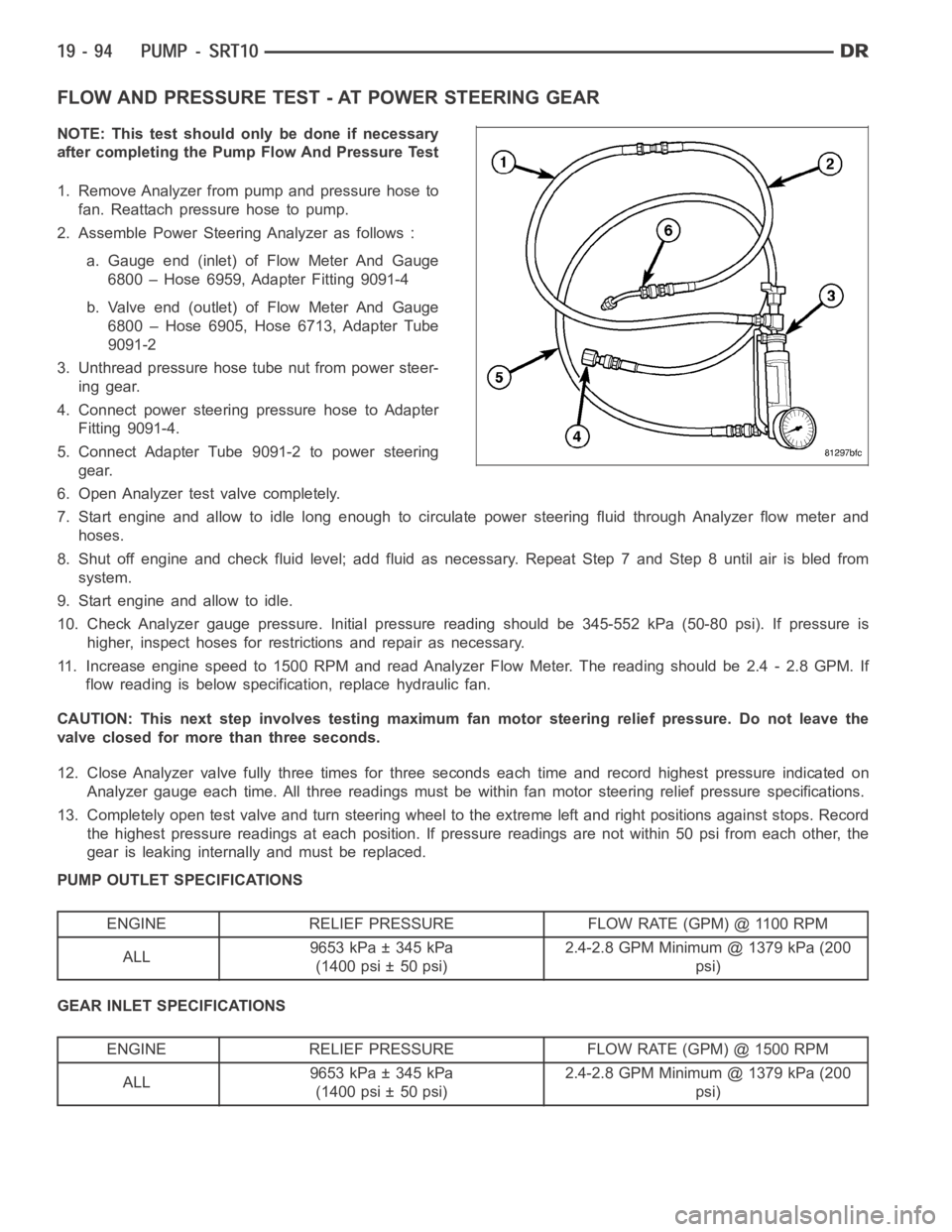
FLOW AND PRESSURE TEST - AT POWER STEERING GEAR
NOTE: This test should only be done if necessary
after completing the Pump Flow And Pressure Test
1. Remove Analyzer from pump and pressure hose to
fan. Reattach pressure hose to pump.
2. Assemble Power Steering Analyzer as follows :
a. Gauge end (inlet) of Flow Meter And Gauge
6800 – Hose 6959, Adapter Fitting 9091-4
b. Valve end (outlet) of Flow Meter And Gauge
6800 – Hose 6905, Hose 6713, Adapter Tube
9091-2
3. Unthread pressure hose tube nut from power steer-
ing gear.
4. Connect power steering pressure hose to Adapter
Fitting 9091-4.
5. Connect Adapter Tube 9091-2 to power steering
gear.
6. Open Analyzer test valve completely.
7. Start engine and allow to idle long enough to circulate power steering fluid through Analyzer flow meter and
hoses.
8. Shut off engine and check fluid level; add fluid as necessary. Repeat Step7andStep8untilairisbledfrom
system.
9. Start engine and allow to idle.
10. Check Analyzer gauge pressure. Initial pressure reading should be 345-552 kPa (50-80 psi). If pressure is
higher, inspect hoses for restrictions and repair as necessary.
11. Increase engine speed to 1500 RPM and read Analyzer Flow Meter. The reading should be 2.4 - 2.8 GPM. If
flow reading is below specification, replace hydraulic fan.
CAUTION: This next step involves testing maximum fan motor steering relief pressure. Do not leave the
valve closed for more than three seconds.
12. Close Analyzer valve fully three times for three seconds each time and record highest pressure indicated on
Analyzer gauge each time. All three readings must be within fan motor steering relief pressure specifications.
13. Completely open test valve and turn steering wheel to the extreme left and right positions against stops. Record
the highest pressure readings at each position. If pressure readings are not within 50 psi from each other, the
gear is leaking internally and must be replaced.
PUMP OUTLET SPECIFICATIONS
ENGINE RELIEF PRESSURE FLOW RATE (GPM) @ 1100 RPM
ALL9653 kPa ± 345 kPa
(1400 psi ± 50 psi)2.4-2.8 GPM Minimum @ 1379 kPa (200
psi)
GEAR INLET SPECIFICATIONS
ENGINE RELIEF PRESSURE FLOW RATE (GPM) @ 1500 RPM
ALL9653 kPa ± 345 kPa
(1400 psi ± 50 psi)2.4-2.8 GPM Minimum @ 1379 kPa (200
psi)
Page 2500 of 5267
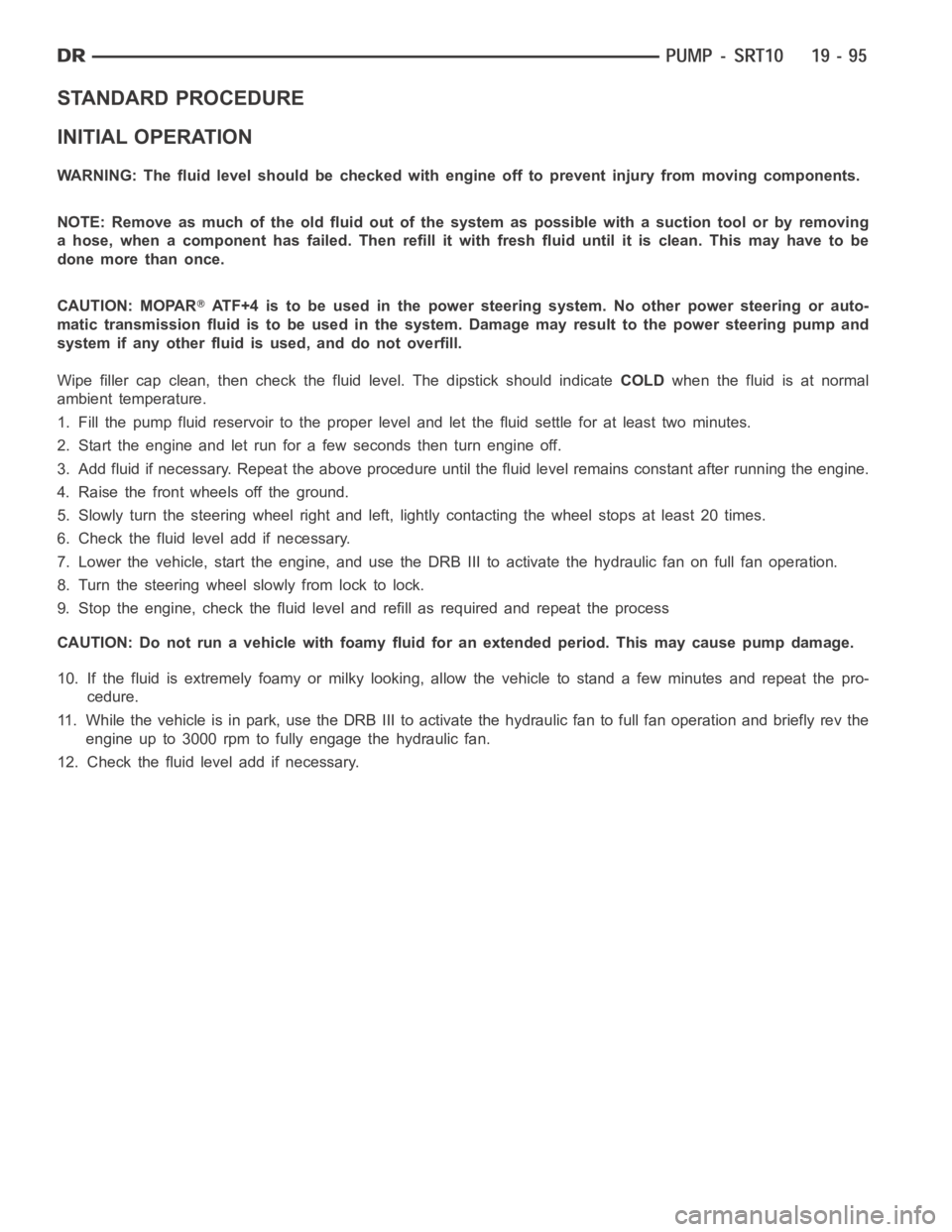
STANDARD PROCEDURE
INITIAL OPERATION
WARNING: The fluid level should be checked with engine off to prevent injury from moving components.
NOTE: Remove as much of the old fluid out of the system as possible with a suction tool or by removing
a hose, when a component has failed. Then refill it with fresh fluid until itis clean. This may have to be
done more than once.
CAUTION: MOPAR
ATF+4 is to be used in the power steering system. No other power steering or auto-
matic transmission fluid is to be used in the system. Damage may result to the power steering pump and
system if any other fluid is used, and do not overfill.
Wipe filler cap clean, then check the fluid level. The dipstick should indicateCOLDwhen the fluid is at normal
ambient temperature.
1. Fill the pump fluid reservoir to the proper level and let the fluid settlefor at least two minutes.
2. Start the engine and let run for a few seconds then turn engine off.
3. Add fluid if necessary. Repeat the above procedure until the fluid levelremains constant after running the engine.
4. Raise the front wheels off the ground.
5. Slowly turn the steering wheel right and left, lightly contacting the wheel stops at least 20 times.
6. Check the fluid level add if necessary.
7. Lower the vehicle, start the engine, and use the DRB III to activate the hydraulic fan on full fan operation.
8. Turn the steering wheel slowly from lock to lock.
9. Stop the engine, check the fluid level and refill as required and repeat the process
CAUTION: Do not run a vehicle with foamy fluid for an extended period. This may cause pump damage.
10. If the fluid is extremely foamy or milky looking, allow the vehicle to stand a few minutes and repeat the pro-
cedure.
11. While the vehicle is in park, use the DRB III to activate the hydraulic fan to full fan operation and briefly rev the
engine up to 3000 rpm to fully engage the hydraulic fan.
12. Check the fluid level add if necessary.
Page 3136 of 5267
When Monitored:
The transmission gear ratio is monitored continuously while the transmission is in gear.
Set Condition:
IfthereisanexcessivechangeininputRPMinanygear.ThisDTCcantakeupto five minutes of problem
identification beforeilluminating the MIL.
Possible Causes
(T52) INPUT SPEED SENSOR SIGNAL CIRCUIT OPEN
(T13) SPEED SENSOR GROUND CIRCUIT OPEN
(T52) INPUT SPEED SENSOR SIGNAL CIRCUIT SHORT TO GROUND
(T13) SPEED SENSOR GROUND CIRCUIT SHORT TO GROUND
(T52) INPUT SPEED SENSOR SIGNAL CIRCUIT SHORT TO VOLTAGE
(T13) SPEED SENSOR GROUND CIRCUIT SHORT TO VOLTAGE
INPUT SPEED SENSOR
POWERTRAIN CONTROL MODULE
Always perform the 45RFE/545RFE Pre-Diagnostic Troubleshooting Procedure before proceeding. (Refer to
21 - TRANSMISSION/TRANSAXLE/AUTOMATIC - 45RFE/545RFE - STANDARD PROCEDURE)
Theory of Operation
The transmission system uses two speed sensors, one to measure input RPM and one to measure output RPM.
These inputs are essential for proper transmission operation. Therefore, the integrity of this data is verified through
the following checks:
1) When in gear, if the gear ratio does not compare to a known gear ratio, the corresponding in-gear trouble code
is set (DTCs P0731–36).
2) An excessive change in input or output speeds indicating signal intermittent which may result in the DTCs P0715
and/or P0720 to set.
3) If the common speed sensor ground circuit is lost, both sensor inputs will read the signal from the input speed
sensor at idle in neutral. Since the input speed sensor reads 60 teeth from the input clutch hub and the output
speed sensor reads 30 teeth from the park gear, the result is an apparent speed ratio of 1:2 and may cause the
DTC P1794 to set when at a stop.
Diagnostic Test
1.CHECK TO SEE IF DTC P0715 IS CURRENT
Start the engine in park.
With the scan tool, monitor the Input Speed Sensor RPM.
Is the Input Speed Sensor RPM below 400 RPM?
Ye s>>
Go To 2
No>>
Go To 9
Page 3336 of 5267
When Monitored:
The gear ratio is monitored continuously while the Transmission is in gear.
Set Condition:
After a controller reset in neutral and a ratio of input to output, of 1 to 2. ThisDTCcantakeuptofiveminutes
of problem identification before illuminating the MIL.
Possible Causes
(T13) SPEED SENSOR GROUND CIRCUIT OPEN
(T13) SPEED SENSOR GROUND CIRCUIT SHORT TO GROUND
(T13) SPEED SENSOR GROUND CIRCUIT SHORT TO VOLTAGE
POWERTRAIN CONTROL MODULE
Always perform the 45RFE/545RFE Pre-Diagnostic Troubleshooting Procedure before proceeding. (Refer to
21 - TRANSMISSION/TRANSAXLE/AUTOMATIC - 45RFE/545RFE - STANDARD PROCEDURE)
Theory of Operation
The transmission system uses two speed sensors, one to measure input RPM and one to measure output RPM.
These inputs are essential for proper transmission operation. Therefore, the integrity of this data is verified through
the following checks:
1) When in gear, if the gear ratio does not compare to a known gear ratio, the corresponding in-gear trouble code
is set (DTCs P0731–36).
2) An excessive change in input or output speeds indicating signal intermittent which may result in the DTCs P0715
and/or P0720 to set.
3) If the common speed sensor ground circuit is lost, both sensor inputs will read the signal from the input speed
sensor at idle in neutral. Since the input speed sensor reads 60 teeth from the input clutch hub and the output
speed sensor reads 30 teeth from the park gear, the result is an apparent speed ratio of 1:2 and may cause the
DTC P1794 to set when at a stop.
Diagnostic Test
1.CHECK TO SEE IF DTC P1794 IS CURRENT
Engine Running, Shift lever in park.
With the scan tool, read the Transmission Output and Input Speed Sensor states.
Is the Output Speed Sensor reading twice the Input Speed Sensor reading?
Ye s>>
Go To 2
No>>
Go To 6
2.PCM AND WIRING
Turn the ignition off to the lock position.
Remove the Ignition Switch Feed fuse from the TIPM.
CAUTION: Removal of the Ignition Switch Feed fuse from the TIPM will prevent the vehicle from being
startedingear.
WARNING: The Ignition Switch Feed fuse must be removed from the TIPM. Failure to do so can result in
personal injury or death.
Install the Transmission Simulator, Miller tool 8333.
With the Transmission Simulator, set the Input/Output Speed selector switch to the
3000/1000position. Turn the
Input/Output Speed switch to
ON.
Ignition on, engine not running.
Page 3340 of 5267
3.L/R CLUTCH CIRCUIT LEAKS IN THE VALVE BODY
Turn the ignition off to the lock position.
Remove the transmission oil pan per the Service Information.
Remove the valve body per the service information.
Check condition of the L/R accumulator springs.
Look for possible leak paths into the L/R clutch hydraulics circuit withinthe valve body.
Were any problems found?
Ye s>>
Repair as necessary.
Perform 45RFE/545RFE TRANSMISSION VERIFICATION TEST - VER 1. (Refer to 21- TRANSMIS-
SION/TRANSAXLE/AUTOMATIC - 45RFE/545RFE - STANDARD PROCEDURE)
No>>
Go To 4
4.AIR CHECK L/R CLUTCH CIRCUITS
Perform an air check on the L/R Clutch circuit per the Service Information.
Watch and listen for L/R Clutch piston movement.
Does the L/R piston stroke and return properly?
Ye s>>
Replace the Transmission/TRS Solenoid Assembly per the service information. With the scan tool, per-
form Quick Learn.
Perform 45RFE/545RFE TRANSMISSION VERIFICATION TEST - VER 1. (Refer to 21- TRANSMIS-
SION/TRANSAXLE/AUTOMATIC - 45RFE/545RFE - STANDARD PROCEDURE)
No>>
Repair internal transmission as necessary. Pay attention to the components related to the L/R clutch. A
broken or weak L/R clutch return spring, Accumulator Spring, and/or dislocated snap ring could cause
this problem.
Perform 45RFE/545RFE TRANSMISSION VERIFICATION TEST - VER 1. (Refer to 21- TRANSMIS-
SION/TRANSAXLE/AUTOMATIC - 45RFE/545RFE - STANDARD PROCEDURE)
5.VERIFY PCM OPERATION
NOTE: The TRANS TEMP DEG must be at least 43° C or 110° F before performing thefollowing steps.
Perform eight learnable starts. A learnable start is defined as follows: Start engine. From a standstill, accelerate
lightly to 80 Kmh or 50 MPH, then brake lightly to a stop. Turn off engine.
With the scan tool, record the CL VOL INDEX (CVI) for all clutches
With the scan tool, perform a BATTERY DISCONNECT.
With the scan tool, read the CVI’s and compare them to the readings recordedbefore the BATTERY DISCONNECT.
Are any of the CVI’s less than 5 or different than before the BATTERY DISCONNECT?
Ye s>>
Using the schematics as a guide, check the Powertrain Control Module (PCM)terminals for corrosion,
damage, or terminal push out. Pay particular attention to all power and ground circuits. If no problems
are found, replace the PCM per the Service Information. With the scan tool,perform QUICK LEARN.
Perform 45RFE/545RFE TRANSMISSION VERIFICATION TEST - VER 1. (Refer to 21- TRANSMIS-
SION/TRANSAXLE/AUTOMATIC - 45RFE/545RFE - STANDARD PROCEDURE)
No>>
Te s t C o m p l e t e .
Page 3342 of 5267
3.2C CLUTCH CIRCUIT LEAKS IN THE VALVE BODY
Turn the ignition off to the lock position.
Remove the transmission oil pan per the Service Information.
Remove the valve body per the service information.
Check condition of the 2C accumulator springs.
Look for possible leak paths into the 2C clutch hydraulics circuit within the valve body.
Were any problems found?
Ye s>>
Repair as necessary.
Perform 45RFE/545RFE TRANSMISSION VERIFICATION TEST - VER 1. (Refer to 21- TRANSMIS-
SION/TRANSAXLE/AUTOMATIC - 45RFE/545RFE - STANDARD PROCEDURE)
No>>
Go To 4
4.AIR CHECK 2C CLUTCH CIRCUIT
Turn the ignition off to the lock position.
Perform an air check on the 2C Clutch circuit per the Service Information.
Watch and listen for 2C Clutch piston movement.
Dose the piston stroke and return properly?
Ye s>>
Replace the Transmission/TRS Solenoid Assembly per the service information. With the scan tool, per-
form Quick Learn.
Perform 45RFE/545RFE TRANSMISSION VERIFICATION TEST - VER 1. (Refer to 21- TRANSMIS-
SION/TRANSAXLE/AUTOMATIC - 45RFE/545RFE - STANDARD PROCEDURE)
No>>
Repair internal transmission as necessary. Pay attention to the componentsrelatedtothe2Cclutch.A
broken or dislodged 2C return spring, snap ring or broken 2C Accumulator Spring could cause this prob-
lem.
Perform 45RFE/545RFE TRANSMISSION VERIFICATION TEST - VER 1. (Refer to 21- TRANSMIS-
SION/TRANSAXLE/AUTOMATIC - 45RFE/545RFE - STANDARD PROCEDURE)
5.VERIFY PCM OPERATION
NOTE: The TRANS TEMP DEG must be at least 43° C or 110° F before performing thefollowing steps.
Perform eight learnable starts. A learnable start is defined as follows: Start engine. From a standstill, accelerate
lightly to 80 Kmh or 50 MPH, then brake lightly to a stop. Turn off engine.
With the scan tool, record the CL VOL INDEX (CVI) for all clutches
With the scan tool, perform a BATTERY DISCONNECT.
With the scan tool, read the CVI’s and compare them to the readings recordedbefore the BATTERY DISCONNECT.
Are any of the CVI’s less than 5 or different than before the BATTERY DISCONNECT?
Ye s>>
Using the schematics as a guide, check the Powertrain Control Module (PCM)terminals for corrosion,
damage, or terminal push out. Pay particular attention to all power and ground circuits. If no problems
are found, replace the PCM per the Service Information. With the scan tool,perform QUICK LEARN.
Perform 45RFE/545RFE TRANSMISSION VERIFICATION TEST - VER 1. (Refer to 21- TRANSMIS-
SION/TRANSAXLE/AUTOMATIC - 45RFE/545RFE - STANDARD PROCEDURE)
No>>
Te s t C o m p l e t e .
Page 3344 of 5267
3.OD CLUTCH CIRCUIT LEAKS IN THE VALVE BODY
Turn the ignition off to the lock position.
Remove the transmission oil pan per the Service Information.
Remove the valve body per the service information.
Check condition of the OD accumulator spring.
Look for possible leak paths into the OD clutch hydraulics circuit within the valve body.
Were any problems found?
Ye s>>
Repair as necessary.
Perform 45RFE/545RFE TRANSMISSION VERIFICATION TEST - VER 1. (Refer to 21- TRANSMIS-
SION/TRANSAXLE/AUTOMATIC - 45RFE/545RFE - STANDARD PROCEDURE)
No>>
Go To 4
4.AIR CHECK OD CLUTCH CIRCUIT
Perform an air check on the OD Clutch circuit per the Service Information.
Watch and listen for OD Clutch piston movement.
Air check all other pump passages and watch for air leakage into the OD clutch passage.
NOTE: There is a bleed orifice between the OD and Reverse Clutch passages, soasmallamountofair
leakage from Reverse to OD is normal.
Were any problems found?
Ye s>>
Repair internal transmission. Pay attention to the OD Clutch. Broken or weak return spring or a dislo-
cated snap ring could cause this problem. If no problems were found in the ODclutch,orifleakageinto
the OD passage was noted, replace Pump Assembly per the Service Information.
Perform 45RFE/545RFE TRANSMISSION VERIFICATION TEST - VER 1. (Refer to 21- TRANSMIS-
SION/TRANSAXLE/AUTOMATIC - 45RFE/545RFE - STANDARD PROCEDURE)
No>>
Replace the Transmission/TRS Solenoid Assembly per the service information. With the scan tool, per-
form Quick Learn.
Perform 45RFE/545RFE TRANSMISSION VERIFICATION TEST - VER 1. (Refer to 21- TRANSMIS-
SION/TRANSAXLE/AUTOMATIC - 45RFE/545RFE - STANDARD PROCEDURE)
5.VERIFY PCM OPERATION
NOTE: The TRANS TEMP DEG must be at least 43° C or 110° F before performing thefollowing steps.
Perform eight learnable starts. A learnable start is defined as follows: Start engine. From a standstill, accelerate
lightly to 80 Kmh or 50 MPH, then brake lightly to a stop. Turn off engine.
With the scan tool, record the CL VOL INDEX (CVI) for all clutches.
With the scan tool, perform a BATTERY DISCONNECT.
With the scan tool, read the CVI’s and compare them to the readings recordedbefore the BATTERY DISCONNECT.
Are any of the CVI’s less than 5 or different than before the BATTERY DISCONNECT?
Ye s>>
Using the schematics as a guide, check the Powertrain Control Module (PCM)terminals for corrosion,
damage, or terminal push out. Pay particular attention to all power and ground circuits. If no problems
are found, replace the PCM per the Service Information. With the scan tool,perform QUICK LEARN.
Perform 45RFE/545RFE TRANSMISSION VERIFICATION TEST - VER 1. (Refer to 21- TRANSMIS-
SION/TRANSAXLE/AUTOMATIC - 45RFE/545RFE - STANDARD PROCEDURE)
No>>
Te s t C o m p l e t e .
Page 3346 of 5267
3.UD CLUTCH CIRCUIT LEAKS IN THE VALVE BODY
Turn the ignition off to the lock position.
Remove the transmission oil pan and valve body per the Service Information.
Check the condition of the UD accumulator springs.
Look for possible leak paths into the UD clutch hydraulics circuit within the valve body.
Were there any problems found?
Ye s>>
Repair as necessary.
Perform 45RFE/545RFE TRANSMISSION VERIFICATION TEST - VER 1. (Refer to 21- TRANSMIS-
SION/TRANSAXLE/AUTOMATIC - 45RFE/545RFE - STANDARD PROCEDURE)
No>>
Go To 4
4.AIR CHECK UD CLUTCH CIRCUIT
Perform an air check on the UD Clutch circuit per the Service Information.
Watch and listen for UD Clutch piston movement.
Air check all other pump passages for air leakage into the UD Clutch circuit.
Were any problems found?
Ye s>>
Repair internal transmission. Pay attention to components related to theUD clutch. Broken or weak
return spring or a dislocated snap ring. If no trouble is found in UD clutch component or UD clutch
leakage was noted in passage, replace the Pump Assembly.
Perform 45RFE/545RFE TRANSMISSION VERIFICATION TEST - VER 1. (Refer to 21- TRANSMIS-
SION/TRANSAXLE/AUTOMATIC - 45RFE/545RFE - STANDARD PROCEDURE)
No>>
Replace the Transmission/TRS Solenoid Assembly per the service information. With the scan tool, per-
form Quick Learn.
Perform 45RFE/545RFE TRANSMISSION VERIFICATION TEST - VER 1. (Refer to 21- TRANSMIS-
SION/TRANSAXLE/AUTOMATIC - 45RFE/545RFE - STANDARD PROCEDURE)
5.VERIFY PCM OPERATION
NOTE: The TRANS TEMP DEG must be at least 43° C or 110° F before performing thefollowing steps.
Perform eight learnable starts. A learnable start is defined as follows: Start engine. From a standstill, accelerate
lightly to 80 Kmh or 50 MPH, then brake lightly to a stop. Turn off engine.
With the scan tool, record the clutch volume index (CVI) for all clutches.
With the scan tool, perform a BATTERY DISCONNECT.
With the scan tool, read the CVI’s and compare them to the readings recordedbefore the BATTERY DISCONNECT.
Are any of the CVI’s less than 5 or different than before the BATTERY DISCONNECT?
Ye s>>
Using the schematics as a guide, check the Powertrain Control Module (PCM)terminals for corrosion,
damage, or terminal push out. Pay particular attention to all power and ground circuits. If no problems
are found, replace the PCM per the Service Information. With the scan tool,perform QUICK LEARN.
Perform 45RFE/545RFE TRANSMISSION VERIFICATION TEST - VER 1. (Refer to 21- TRANSMIS-
SION/TRANSAXLE/AUTOMATIC - 45RFE/545RFE - STANDARD PROCEDURE)
No>>
Te s t C o m p l e t e .