DODGE RAM SRT-10 2006 Service Repair Manual
RAM SRT-10 2006
DODGE
DODGE
https://www.carmanualsonline.info/img/12/56917/w960_56917-0.png
DODGE RAM SRT-10 2006 Service Repair Manual
Trending: suspension, tire size, reset, wheelbase, headlamp, fuel filter, seat memory
Page 2651 of 5267
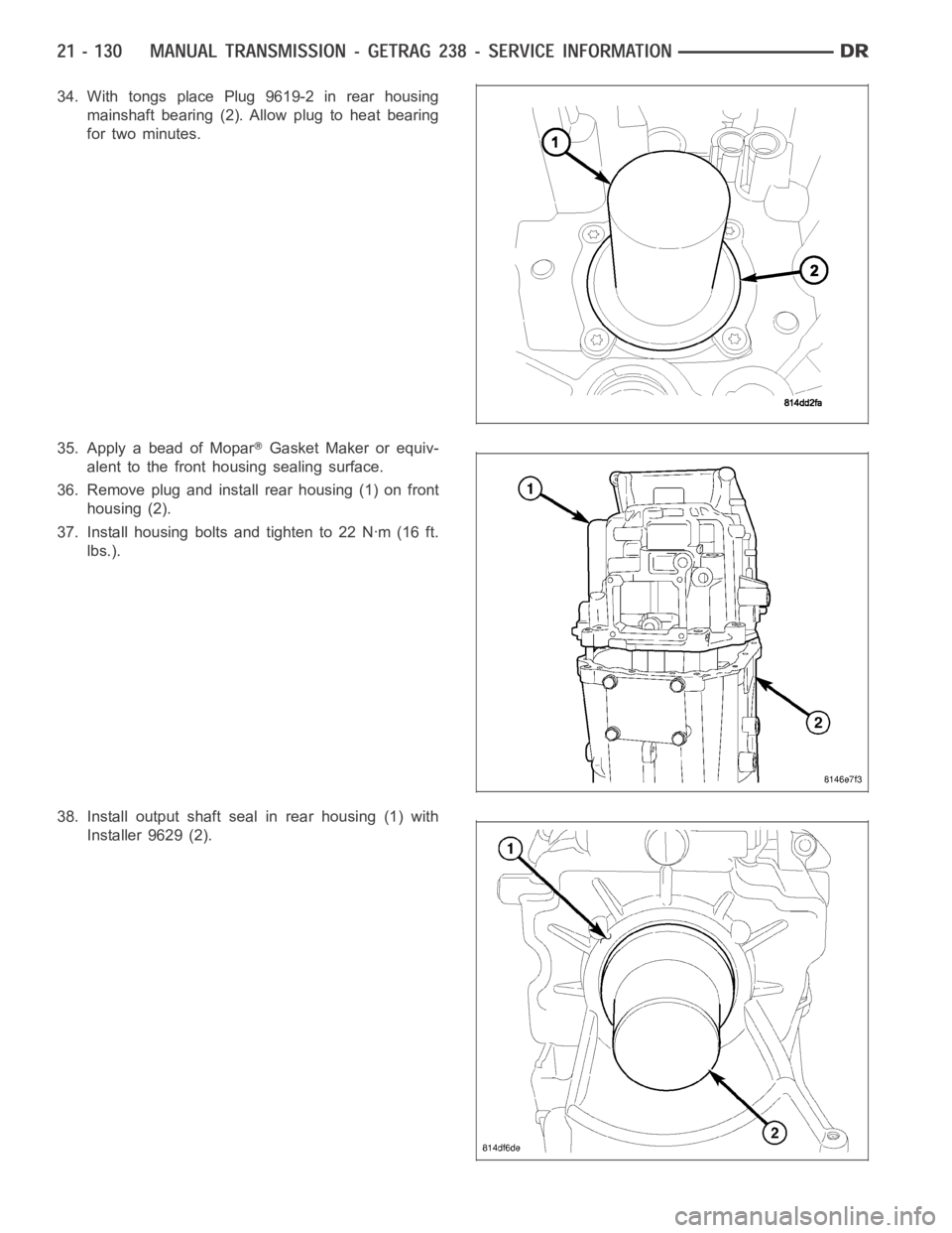
34. With tongs place Plug 9619-2 in rear housing
mainshaft bearing (2). Allow plug to heat bearing
for two minutes.
35. Apply a bead of Mopar
Gasket Maker or equiv-
alent to the front housing sealing surface.
36. Remove plug and install rear housing (1) on front
housing (2).
37. Install housing bolts and tighten to 22 Nꞏm (16 ft.
lbs.).
38. Install output shaft seal in rear housing (1) with
Installer 9629 (2).
Page 2652 of 5267
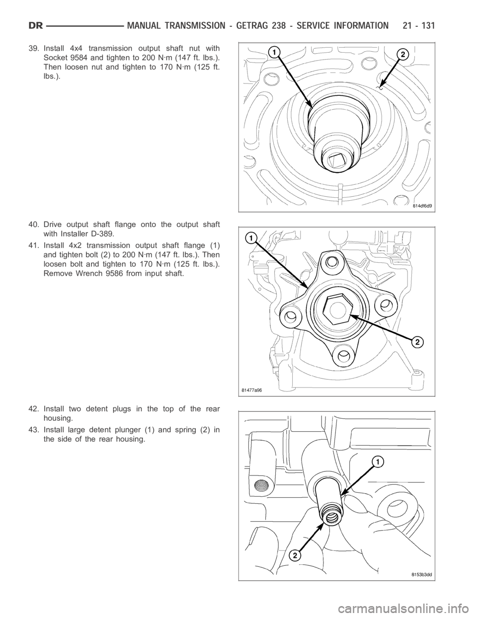
39. Install 4x4 transmission output shaft nut with
Socket 9584 and tighten to 200 Nꞏm (147 ft. lbs.).
Then loosen nut and tighten to 170 Nꞏm (125 ft.
lbs.).
40. Drive output shaft flange onto the output shaft
with Installer D-389.
41. Install 4x2 transmission output shaft flange (1)
and tighten bolt (2) to 200 Nꞏm (147 ft. lbs.). Then
loosen bolt and tighten to 170 Nꞏm (125 ft. lbs.).
Remove Wrench 9586 from input shaft.
42. Install two detent plugs in the top of the rear
housing.
43. Install large detent plunger (1) and spring (2) in
the side of the rear housing.
Page 2653 of 5267
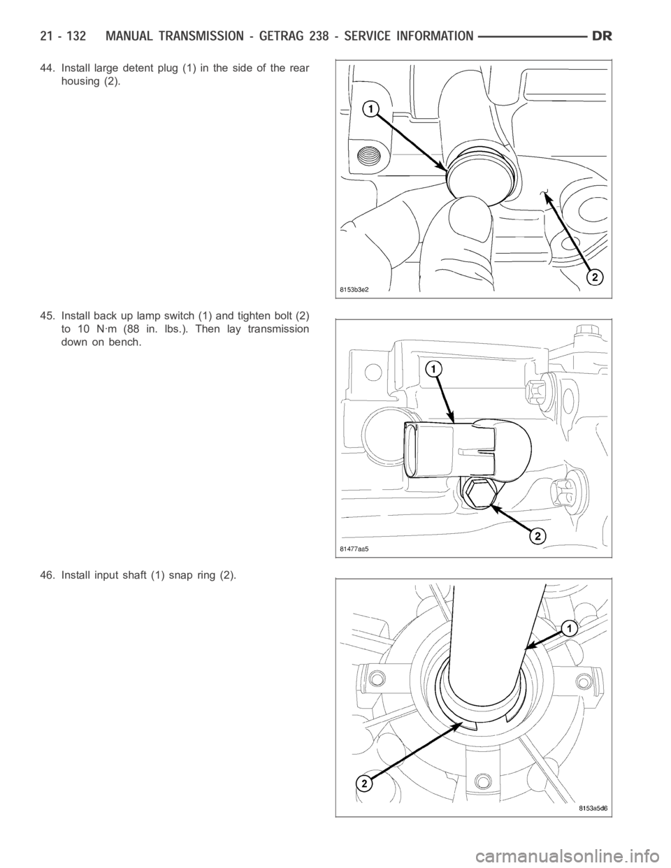
44. Install large detent plug (1) in the side of the rear
housing (2).
45. Install back up lamp switch (1) and tighten bolt (2)
to 10 Nꞏm (88 in. lbs.). Then lay transmission
down on bench.
46. Install input shaft (1) snap ring (2).
Page 2654 of 5267
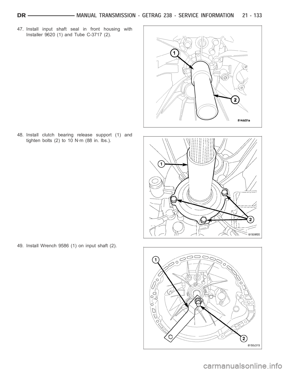
47. Install input shaft seal in front housing with
Installer 9620 (1) and Tube C-3717 (2).
48. Install clutch bearing release support (1) and
tighten bolts (2) to 10 Nꞏm (88 in. lbs.).
49. Install Wrench 9586 (1) on input shaft (2).
Page 2655 of 5267
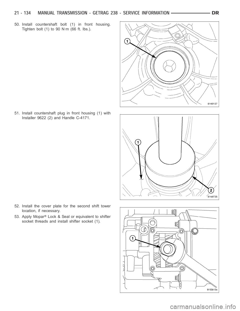
50. Install countershaft bolt (1) in front housing.
Tighten bolt (1) to 90 Nꞏm (66 ft. lbs.).
51. Install countershaft plug in front housing (1) with
Installer 9622 (2) and Handle C-4171.
52. Install the cover plate for the second shift tower
location, if necessary.
53. Apply Mopar
Lock & Seal or equivalent to shifter
socket threads and install shifter socket (1).
Page 2656 of 5267
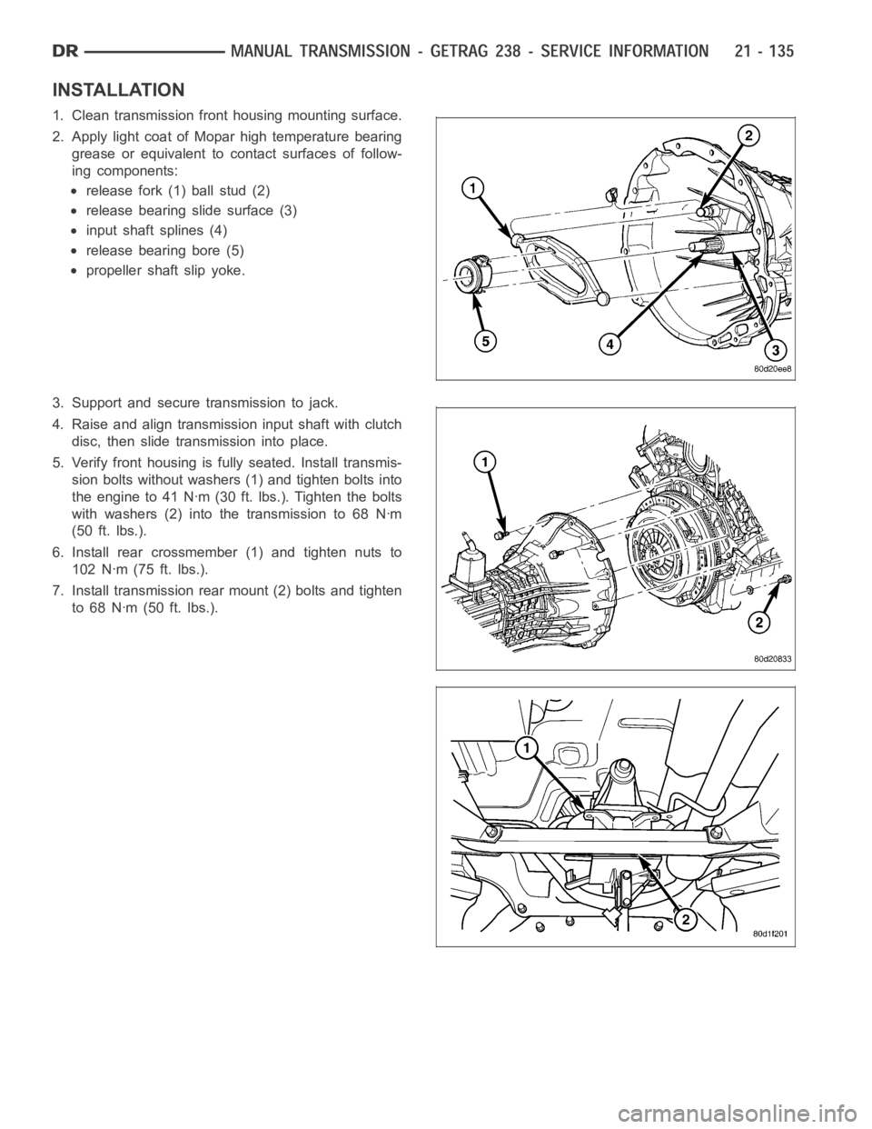
INSTALLATION
1. Clean transmission front housing mounting surface.
2. Apply light coat of Mopar high temperature bearing
grease or equivalent to contact surfaces of follow-
ing components:
release fork (1) ball stud (2)
release bearing slide surface (3)
input shaft splines (4)
release bearing bore (5)
propeller shaft slip yoke.
3. Support and secure transmission to jack.
4. Raise and align transmission input shaft with clutch
disc, then slide transmission into place.
5. Verify front housing is fully seated. Install transmis-
sion bolts without washers (1) and tighten bolts into
the engine to 41 Nꞏm (30 ft. lbs.). Tighten the bolts
with washers (2) into the transmission to 68 Nꞏm
(50 ft. lbs.).
6. Install rear crossmember (1) and tighten nuts to
102 Nꞏm (75 ft. lbs.).
7. Install transmission rear mount (2) bolts and tighten
to 68 Nꞏm (50 ft. lbs.).
Page 2657 of 5267
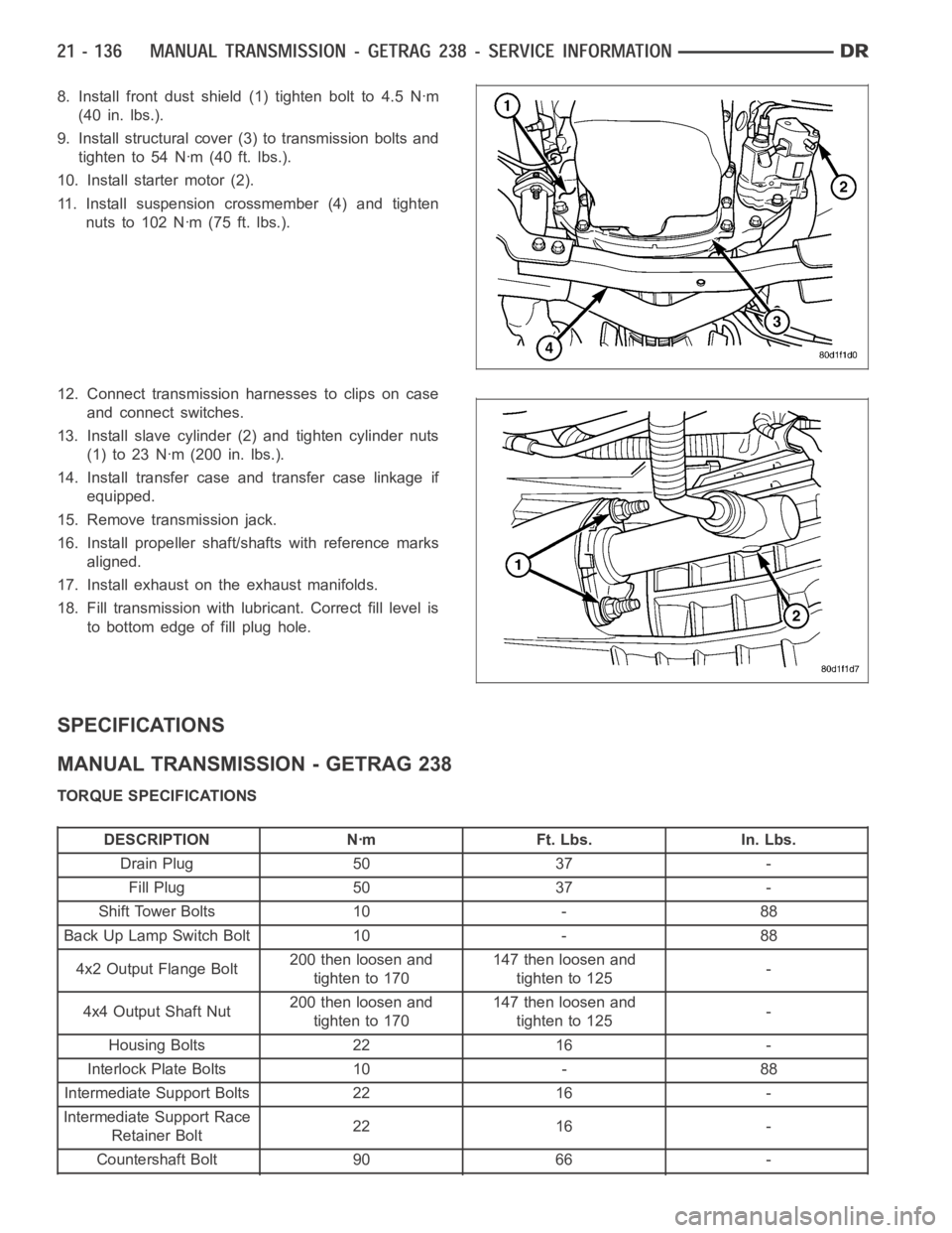
8. Install front dust shield (1) tighten bolt to 4.5 Nꞏm
(40 in. lbs.).
9. Install structural cover (3) to transmission bolts and
tighten to 54 Nꞏm (40 ft. lbs.).
10. Install starter motor (2).
11. Install suspension crossmember (4) and tighten
nuts to 102 Nꞏm (75 ft. lbs.).
12. Connect transmission harnesses to clips on case
and connect switches.
13. Install slave cylinder (2) and tighten cylinder nuts
(1)to23Nꞏm(200in.lbs.).
14. Install transfer case and transfer case linkage if
equipped.
15. Remove transmission jack.
16. Install propeller shaft/shafts with reference marks
aligned.
17. Install exhaust on the exhaust manifolds.
18. Fill transmission with lubricant. Correct fill level is
to bottom edge of fill plug hole.
SPECIFICATIONS
MANUAL TRANSMISSION - GETRAG 238
TORQUE SPECIFICATIONS
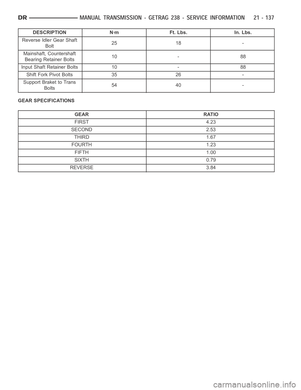
DESCRIPTION Nꞏm Ft. Lbs. In. Lbs.
Drain Plug 50 37 -
Fill Plug 50 37 -
Shift Tower Bolts 10 - 88
Back Up Lamp Switch Bolt 10 - 88
4x2 Output Flange Bolt200 then loosen and
tighten to 170147 then loosen and
tighten to 125-
4x4 Output Shaft Nut200 then loosen and
tighten to 170147 then loosen and
tighten to 125-
Housing Bolts 22 16 -
Interlock Plate Bolts 10 - 88
Intermediate Support Bolts 22 16 -
Intermediate Support Race
Retainer Bolt22 16 -
Countershaft Bolt 90 66 -
Page 2658 of 5267
DESCRIPTION Nꞏm Ft. Lbs. In. Lbs.
Reverse Idler Gear Shaft
Bolt25 18 -
Mainshaft, Countershaft
Bearing Retainer Bolts10 - 88
Input Shaft Retainer Bolts 10 - 88
Shift Fork Pivot Bolts 35 26 -
Support Braket to Trans
Bolts54 40 -
GEAR SPECIFICATIONS
GEAR RATIO
FIRST 4.23
SECOND 2.53
THIRD 1.67
FOURTH 1.23
FIFTH 1.00
SIXTH 0.79
REVERSE 3.84
Page 2659 of 5267
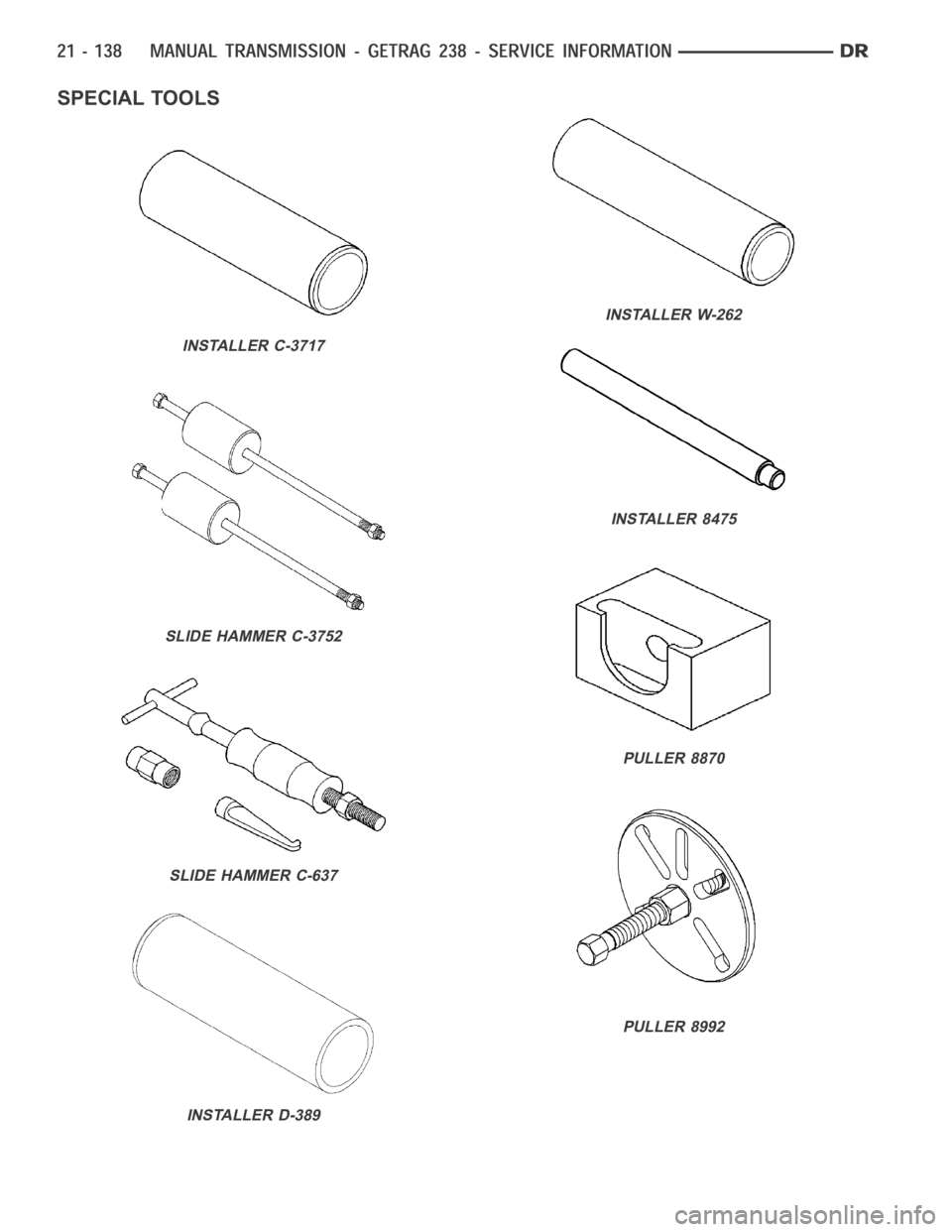
SPECIAL TOOLS
INSTALLER C-3717
SLIDE HAMMER C-3752
SLIDE HAMMER C-637
INSTALLER D-389
INSTALLER W-262
INSTALLER 8475
PULLER 8870
PULLER 8992
Page 2660 of 5267
BRIDGE 938
PULLER 9583
SOCKET 9584
PULLER 9585
WRENCH 9586
PULLER 9609
REMOVER/INSTALLER 9617
PULLER 9618
Trending: length, dead battery, bolt pattern, tow, wheelbase, fuel filter, fuel tank capacity
