DODGE RAM SRT-10 2006 Service Repair Manual
RAM SRT-10 2006
DODGE
DODGE
https://www.carmanualsonline.info/img/12/56917/w960_56917-0.png
DODGE RAM SRT-10 2006 Service Repair Manual
Trending: height adjustment, tailgate, hood open, bulb, washer fluid, fuse diagram, warning
Page 2681 of 5267
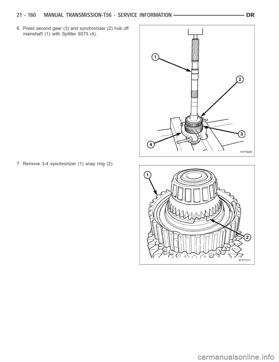
6. Press second gear (3) and synchronizer (2) hub off
mainshaft (1) with Splitter 9375 (4).
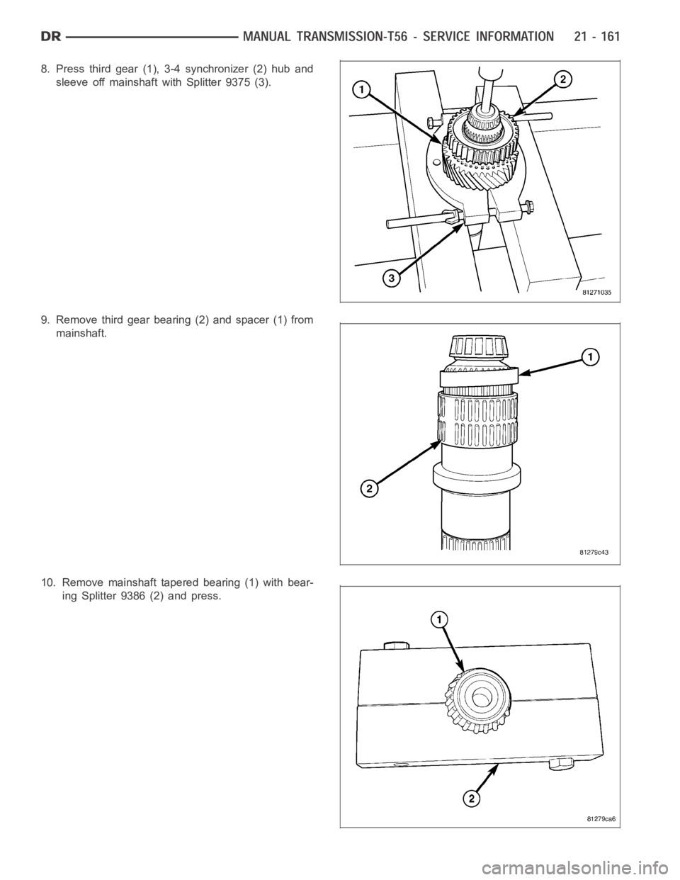
7. Remove 3-4 synchronizer (1) snap ring (2).
Page 2682 of 5267
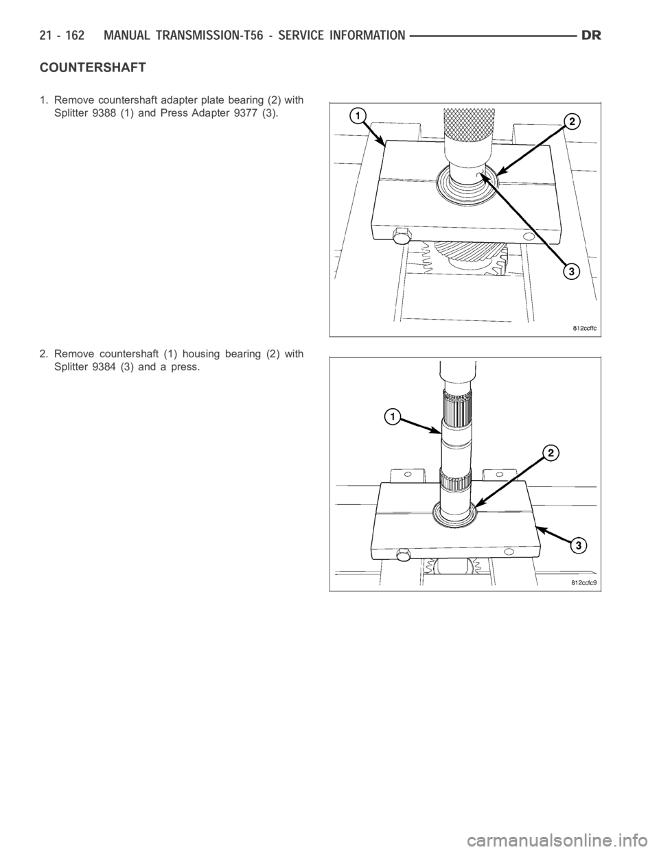
8. Press third gear (1), 3-4 synchronizer (2) hub and
sleeve off mainshaft with Splitter 9375 (3).
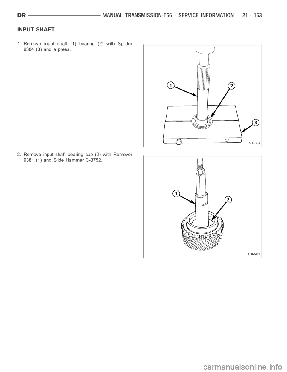
9. Remove third gear bearing (2) and spacer (1) from
mainshaft.
10. Remove mainshaft tapered bearing (1) with bear-
ing Splitter 9386 (2) and press.
Page 2683 of 5267
COUNTERSHAFT
1. Remove countershaft adapter plate bearing (2) with
Splitter 9388 (1) and Press Adapter 9377 (3).
2. Remove countershaft (1) housing bearing (2) with
Splitter 9384 (3) and a press.
Page 2684 of 5267
INPUT SHAFT
1. Remove input shaft (1) bearing (2) with Splitter
9384 (3) and a press.
2. Remove input shaft bearing cup (2) with Remover
9381 (1) and Slide Hammer C-3752.
Page 2685 of 5267
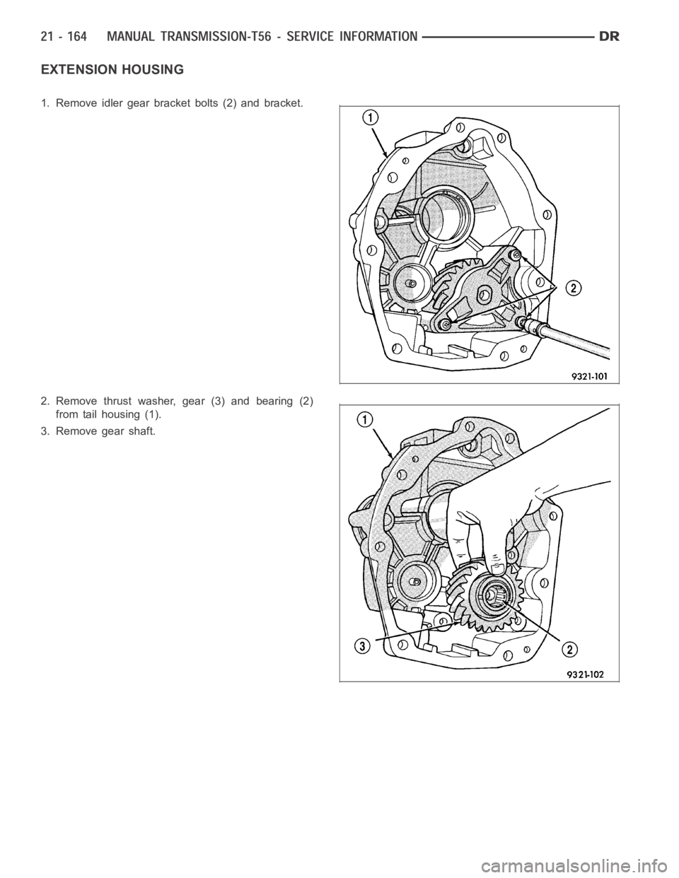
EXTENSION HOUSING
1. Remove idler gear bracket bolts (2) and bracket.
2. Remove thrust washer, gear (3) and bearing (2)
from tail housing (1).
3. Remove gear shaft.
Page 2686 of 5267
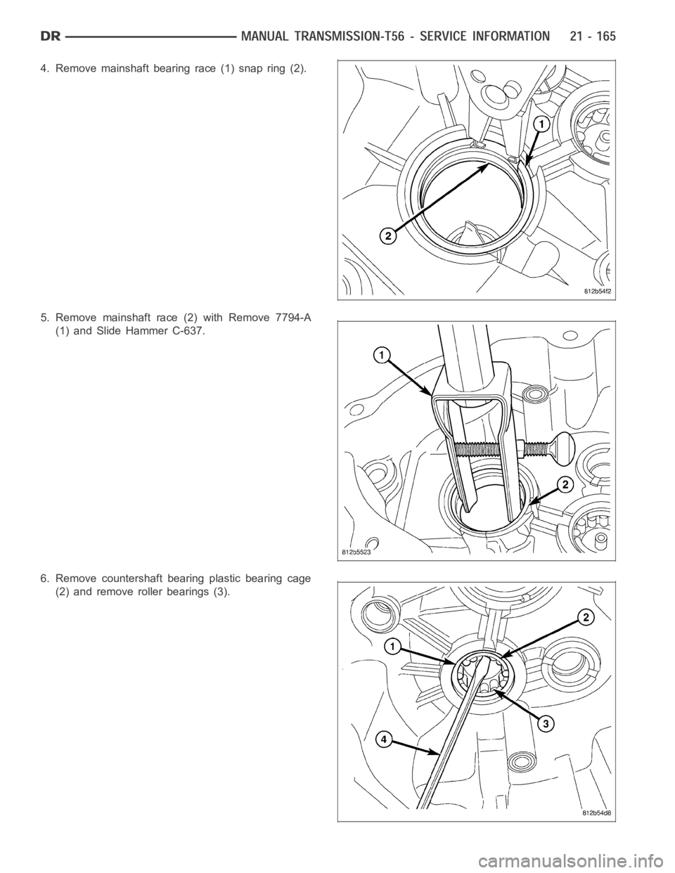
4. Remove mainshaft bearing race (1) snap ring (2).
5. Remove mainshaft race (2) with Remove 7794-A
(1) and Slide Hammer C-637.
6. Remove countershaft bearing plastic bearing cage
(2) and remove roller bearings (3).
Page 2687 of 5267
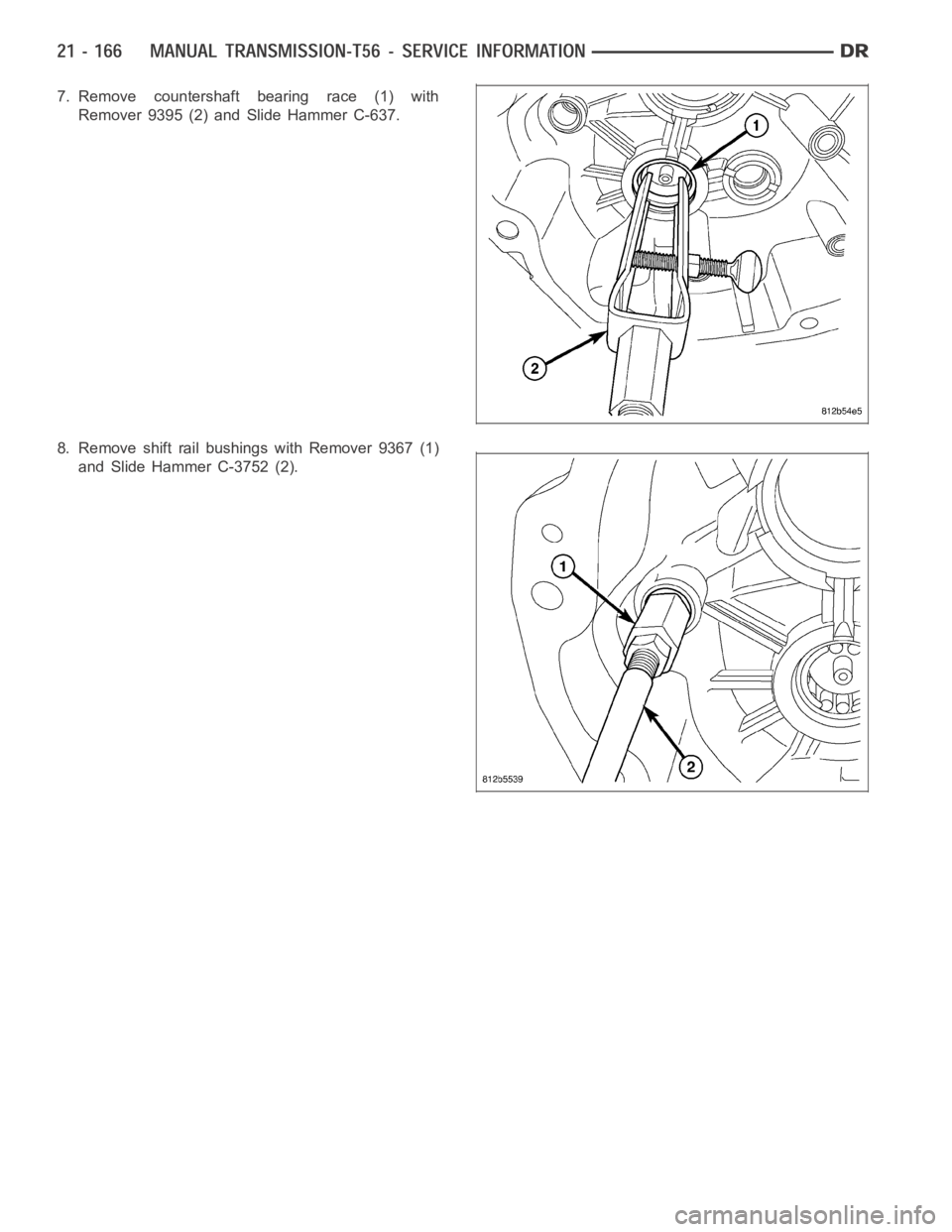
7. Remove countershaft bearing race (1) with
Remover 9395 (2) and Slide Hammer C-637.
8. Remove shift rail bushings with Remover 9367 (1)
and Slide Hammer C-3752 (2).
Page 2688 of 5267
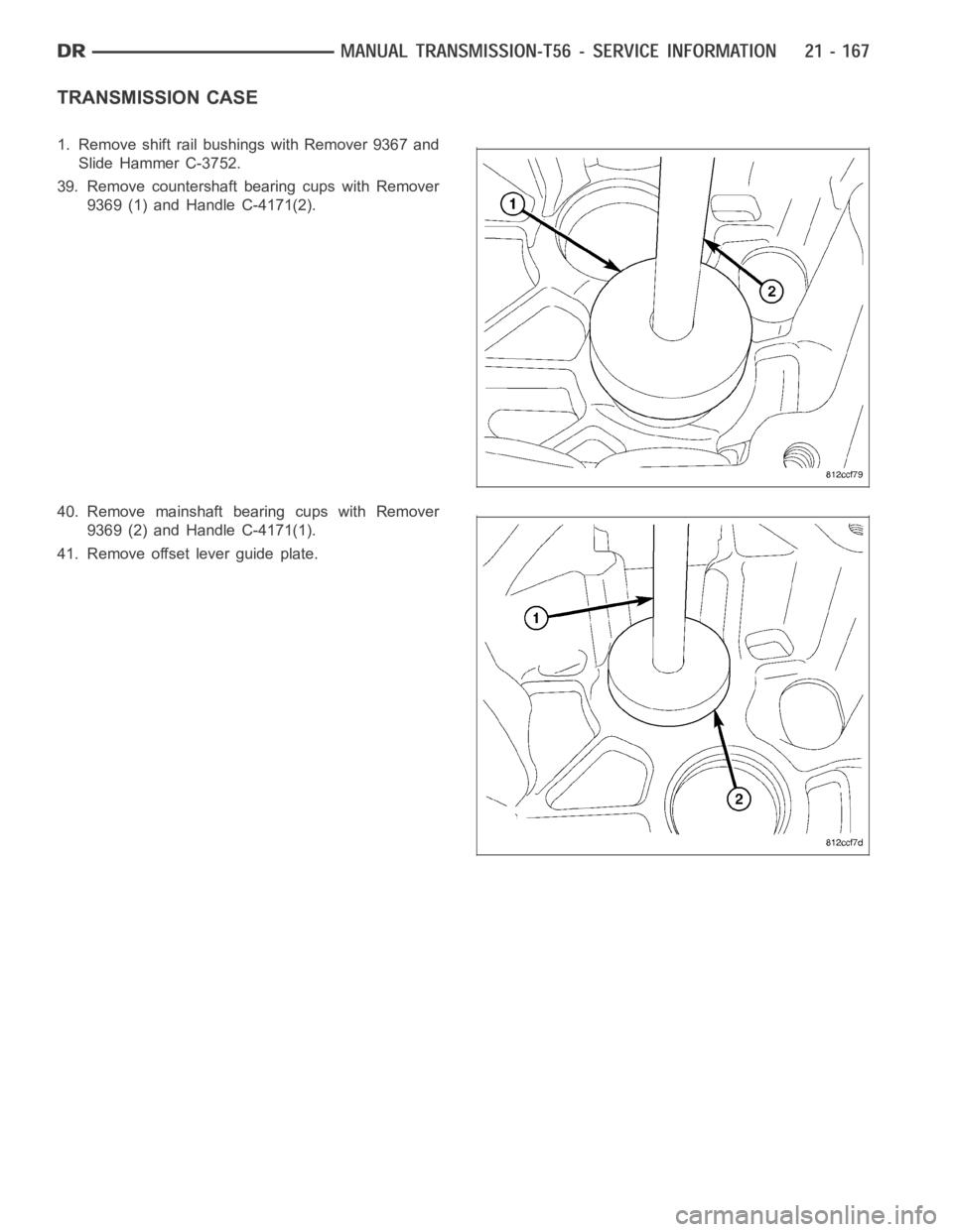
TRANSMISSION CASE
1. Remove shift rail bushings with Remover 9367 and
Slide Hammer C-3752.
39. Remove countershaft bearing cups with Remover
9369 (1) and Handle C-4171(2).
40. Remove mainshaft bearing cups with Remover
9369 (2) and Handle C-4171(1).
41. Remove offset lever guide plate.
Page 2689 of 5267
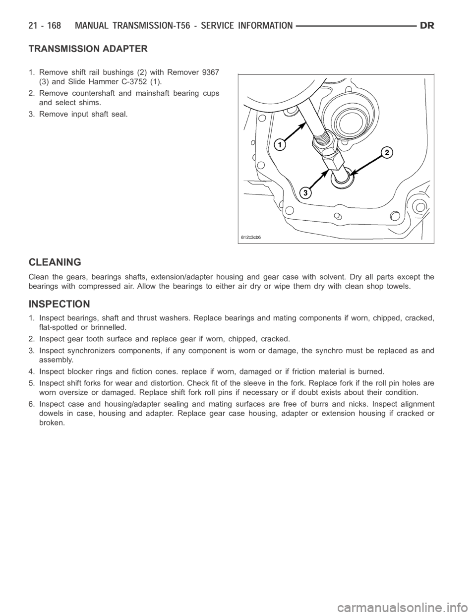
TRANSMISSION ADAPTER
1. Remove shift rail bushings (2) with Remover 9367
(3) and Slide Hammer C-3752 (1).
2. Remove countershaft and mainshaft bearing cups
and select shims.
3. Remove input shaft seal.
CLEANING
Clean the gears, bearings shafts, extension/adapter housing and gear case with solvent. Dry all parts except the
bearings with compressed air. Allow the bearings to either air dry or wipe them dry with clean shop towels.
INSPECTION
1. Inspect bearings, shaft and thrust washers. Replace bearings and mating components if worn, chipped, cracked,
flat-spotted or brinnelled.
2. Inspect gear tooth surface and replace gear if worn, chipped, cracked.
3. Inspect synchronizers components, if any component is worn or damage, the synchro must be replaced as and
assembly.
4. Inspect blocker rings and fiction cones. replace if worn, damaged or if friction material is burned.
5. Inspect shift forks for wear and distortion. Check fit of the sleeve in the fork. Replace fork if the roll pin holes are
worn oversize or damaged. Replace shift fork roll pins if necessary or if doubt exists about their condition.
6. Inspect case and housing/adapter sealing and mating surfaces are free of burrs and nicks. Inspect alignment
dowels in case, housing and adapter. Replace gear case housing, adapter orextension housing if cracked or
broken.
Page 2690 of 5267
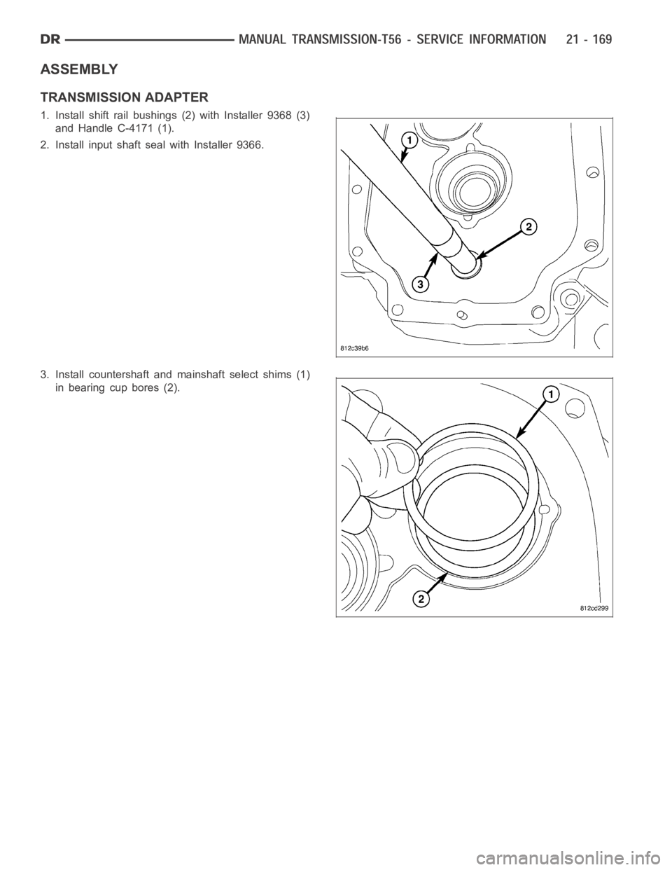
ASSEMBLY
TRANSMISSION ADAPTER
1. Install shift rail bushings (2) with Installer 9368 (3)
and Handle C-4171 (1).
2. Install input shaft seal with Installer 9366.
3. Install countershaft and mainshaft select shims (1)
in bearing cup bores (2).
Trending: change wheel, automatic transmission, air suspension, brake fluid, width, Crank pulley bolt, relay
