check engine DODGE RAM SRT-10 2006 Service Owner's Manual
[x] Cancel search | Manufacturer: DODGE, Model Year: 2006, Model line: RAM SRT-10, Model: DODGE RAM SRT-10 2006Pages: 5267, PDF Size: 68.7 MB
Page 59 of 5267
6.TOTALLY INTEGRATED POWER MODULE
NOTE: Before continuing, check the TIPM harness connector terminals for corrosion, damage, or terminal
push out. Repair as necessary.
Using the schematics as a guide, inspect the wire harness and connectors.
Pay particular attention to all Power and Ground circuits.
Were any problems found?
Ye s>>
Repair as necessary.
Perform the POWERTRAIN VERIFICATION TEST. (Refer to 9 - ENGINE - STANDARD PROCEDURE)
No>>
Replace the Totally Integrated Power Module per Service Information.
Perform the BODY VERIFICATION TEST – VER 1. (Refer to 8 - ELECTRICAL/ELECTRONIC CON-
TROL MODULES - STANDARD PROCEDURE)
Page 63 of 5267
5.TOTALLY INTEGRATED POWER MODULE
NOTE: Before continuing, check the TIPM harness connector terminals for corrosion, damage, or terminal
push out. Repair as necessary.
Using the schematics as a guide, inspect the wire harness and connectors.
Pay particular attention to all Power and Ground circuits.
Were any problems found?
Ye s>>
Repair as necessary.
Perform the POWERTRAIN VERIFICATION TEST. (Refer to 9 - ENGINE - STANDARD PROCEDURE)
No>>
Replace the Totally Integrated Power Module in accordance with the Service Information.
Perform the BODY VERIFICATION TEST – VER 1. (Refer to 8 - ELECTRICAL/ELECTRONIC CON-
TROL MODULES - STANDARD PROCEDURE)
Page 65 of 5267
When Monitored:
With the ignition on. Battery voltage greater than 10.4 volts. TIPM requesting A/C Clutch operation.
Set Condition:
An overcurrent condition is detected in the A/C Clutch control output circuit. One Trip Fault. Three good trips
to turn off the MIL.
Possible Causes
TERMINAL DAMAGE OR CORROSION
A/C CLUTCH GROUND HIGH RESISTANCE
(C3) A/C CLUTCH CONTROL OUTPUT CIRCUIT HIGH RESISTANCE
A/C COMPRESSOR CLUTCH
TIPM
Always perform the Pre-Diagnostic Troubleshooting procedure before proceeding. (Refer to 9 - ENGINE -
DIAGNOSIS AND TESTING).
Diagnostic Test
1.A/C CLUTCH OPERATION
Ignition on, engine not running.
With a scan tool in the TIPM Actuators, actuate the A/C Clutch.
Is the A/C Clutch actuating?
Ye s>>
Refer to the INTERMITTENT CONDITION Diagnostic Procedure.
Perform the POWERTRAIN VERIFICATION TEST. (Refer to 9 - ENGINE - STANDARD PROCEDURE)
No>>
Go To 2
2.VISUAL AND PHYSICAL CONNECTOR AND TERMINAL INSPECTION
Turn the ignition off.
Disconnect the TIPM C9 harness connector.
Disconnect the A/C Clutch harness connector.
Inspect the terminal and connector condition. Check for signs of corrosion build up or damage the would compro-
mise the terminal to controller pin connector.
NOTE: Make sure that all in-line connectors are inspected for corrosion and/or damage.
Visually inspect the wiring harness. Look for any chafed, pierced, pinched or partially broken wires hidden in the
wire insulation.
Were any of the above conditions found?
Ye s>>
Repair or replace as necessary.
Perform the POWERTRAIN VERIFICATION TEST. (Refer to 9 - ENGINE - STANDARD PROCEDURE)
No>>
Go To 3
Page 78 of 5267
4.(T40) STARTER RELAY OUTPUT CIRCUIT SHORTED TO GROUND
Disconnect the C9 TIPM harness connector.
Measure the resistance between ground and the (T40) Starter Relay Output circuit at the C9 TIPM harness con-
nector.
Istheresistancebelow100ohms?
Ye s>>
Repair the short to ground in the (T40) Starter Relay Output circuit.
Perform the POWERTRAIN VERIFICATION TEST. (Refer to 9 - ENGINE - STANDARD PROCEDURE)
No>>
Go To 5
5.(T40) STARTER RELAY OUTPUT CIRCUIT EXCESSIVE RESISTANCE
Measure the resistance of the (T40) Starter Relay Output circuit from the Starter Relay terminal to the C9 TIPM
harness connector.
Is the resistance above 5.0 ohms?
Ye s>>
Repair the excessive resistance in the (T40) Starter Relay Feed circuit.
Perform the POWERTRAIN VERIFICATION TEST. (Refer to 9 - ENGINE - STANDARD PROCEDURE)
No>>
Go To 6
6.STARTER RELAY
Install a known good Relay.
Ignition on, engine not running.
Clear the TIPM DTCs.
Attempt to start the engine.
Does the P127A reset?
Ye s>>
Go To 7
No>>
Replace the Starter Relay.
Perform the POWERTRAIN VERIFICATION TEST. (Refer to 9 - ENGINE - STANDARD PROCEDURE)
7.TOTALLY INTEGRATED POWER MODULE
NOTE: Before continuing, check the TIPM harness connector terminals for corrosion, damage, or terminal
push out. Repair as necessary.
Using the schematics as a guide, inspect the wire harness and connectors.
Pay particular attention to all Power and Ground circuits.
Were any problems found?
Ye s>>
Repair as necessary.
Perform the POWERTRAIN VERIFICATION TEST. (Refer to 9 - ENGINE - STANDARD PROCEDURE)
No>>
Replace the Totally Integrated Power Module per Service Information.
Perform the BODY VERIFICATION TEST – VER 1. (Refer to 8 - ELECTRICAL/ELECTRONIC CON-
TROL MODULES - STANDARD PROCEDURE)
Page 81 of 5267
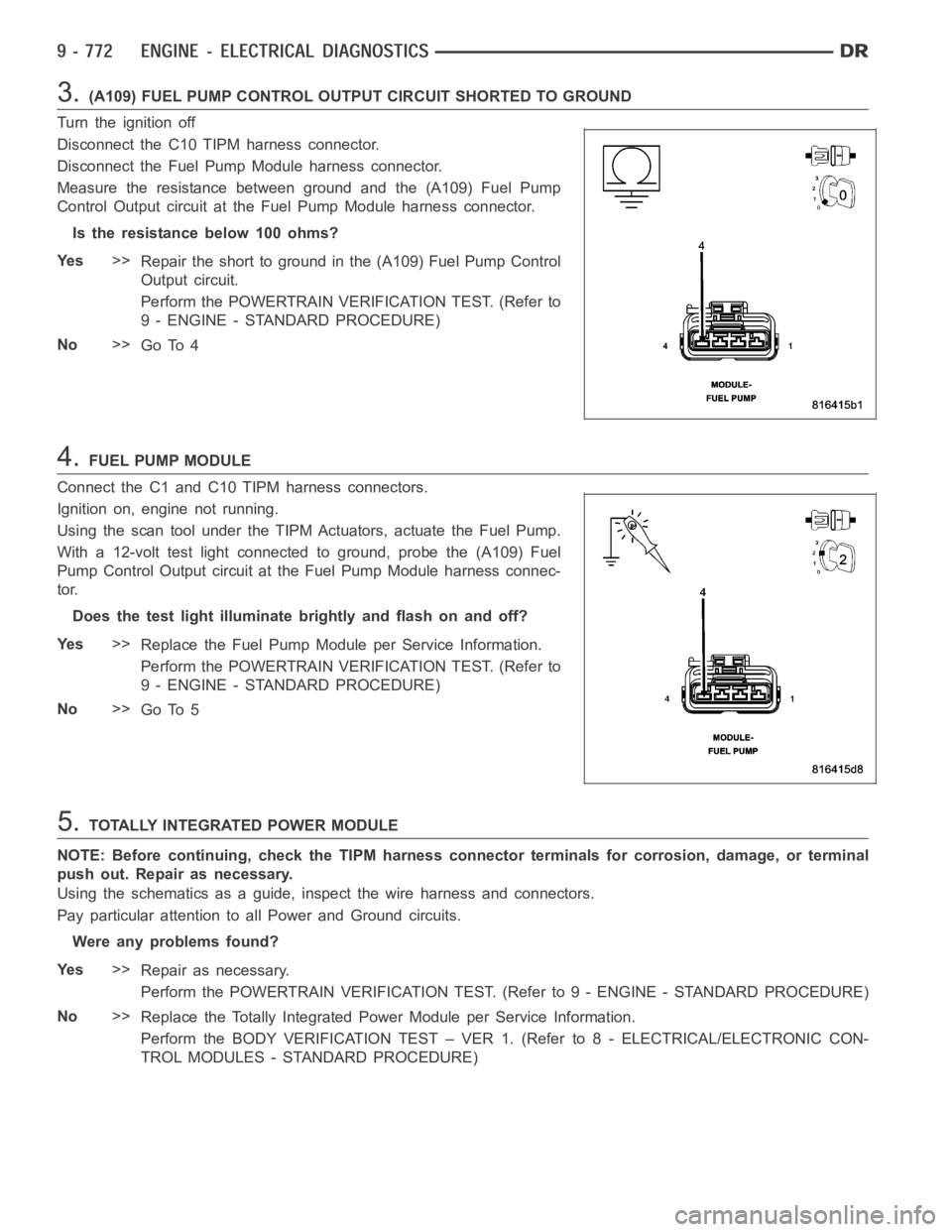
3.(A109) FUEL PUMP CONTROL OUTPUT CIRCUIT SHORTED TO GROUND
Turn the ignition off
Disconnect the C10 TIPM harness connector.
Disconnect the Fuel Pump Module harness connector.
Measure the resistance between ground and the (A109) Fuel Pump
Control Output circuit at the Fuel Pump Module harness connector.
Istheresistancebelow100ohms?
Ye s>>
Repair the short to ground in the (A109) Fuel Pump Control
Output circuit.
Perform the POWERTRAIN VERIFICATION TEST. (Refer to
9 - ENGINE - STANDARD PROCEDURE)
No>>
Go To 4
4.FUEL PUMP MODULE
Connect the C1 and C10 TIPM harness connectors.
Ignition on, engine not running.
Using the scan tool under the TIPM Actuators, actuate the Fuel Pump.
With a 12-volt test light connected to ground, probe the (A109) Fuel
Pump Control Output circuit at the Fuel Pump Module harness connec-
tor.
Does the test light illuminate brightly and flash on and off?
Ye s>>
Replace the Fuel Pump Module per Service Information.
Perform the POWERTRAIN VERIFICATION TEST. (Refer to
9 - ENGINE - STANDARD PROCEDURE)
No>>
Go To 5
5.TOTALLY INTEGRATED POWER MODULE
NOTE: Before continuing, check the TIPM harness connector terminals for corrosion, damage, or terminal
push out. Repair as necessary.
Using the schematics as a guide, inspect the wire harness and connectors.
Pay particular attention to all Power and Ground circuits.
Were any problems found?
Ye s>>
Repair as necessary.
Perform the POWERTRAIN VERIFICATION TEST. (Refer to 9 - ENGINE - STANDARD PROCEDURE)
No>>
Replace the Totally Integrated Power Module per Service Information.
Perform the BODY VERIFICATION TEST – VER 1. (Refer to 8 - ELECTRICAL/ELECTRONIC CON-
TROL MODULES - STANDARD PROCEDURE)
Page 85 of 5267
6.TOTALLY INTEGRATED POWER MODULE
NOTE: Before continuing, check the TIPM harness connector terminals for corrosion, damage, or terminal
push out. Repair as necessary.
Using the schematics as a guide, inspect the wire harness and connectors.
Pay particular attention to all Power and Ground circuits.
Were any problems found?
Ye s>>
Repair as necessary.
Perform the POWERTRAIN VERIFICATION TEST. (Refer to 9 - ENGINE - STANDARD PROCEDURE)
No>>
Replace the Totally Integrated Power Module per Service Information.
Perform the BODY VERIFICATION TEST – VER 1. (Refer to 9 - ENGINE - STANDARD PROCEDURE)
Page 89 of 5267
5.TOTALLY INTEGRATED POWER MODULE
NOTE: Before continuing, check the TIPM harness connector terminals for corrosion, damage, or terminal
push out. Repair as necessary.
Using the schematics as a guide, inspect the wire harness and connectors.
Pay particular attention to all Power and Ground circuits.
Were any problems found?
Ye s>>
Repair as necessary.
Perform the POWERTRAIN VERIFICATION TEST. (Refer to 9 - ENGINE - STANDARD PROCEDURE)
No>>
Replace the Totally Integrated Power Module in accordance with the Service Information.
Perform the BODY VERIFICATION TEST – VER 1. (Refer to 9 - ENGINE - STANDARD PROCEDURE)
Page 91 of 5267
When Monitored:
With the ignition on. Battery voltage greater than 10.4 volts. TIPM requesting Fuel Pump operation.
Set Condition:
An overcurrent condition is detected in the fuel pump control output circuit. One Trip Fault. Three good trips to
turn off the MIL.
Possible Causes
TERMINAL DAMAGE OR CORROSION
FUEL PUMP MOTOR GROUND HIGH RESISTANCE
(A109) FUEL PUMP CONTROL OUTPUT CIRCUIT HIGH RESISTANCE
FUEL PUMP MOTOR
TIPM
Always perform the Pre-Diagnostic Troubleshooting procedure before proceeding. (Refer to 9 - ENGINE -
DIAGNOSIS AND TESTING).
Diagnostic Test
1.FUEL PUMP OPERATION
Ignition on, engine not running.
With a scan tool in the TIPM Actuators, actuate the Fuel Pump.
Is the Fuel Pump operating?
Ye s>>
Refer to the INTERMITTENT CONDITION Diagnostic Procedure.
Perform the POWERTRAIN VERIFICATION TEST. (Refer to 9 - ENGINE - STANDARD PROCEDURE)
No>>
Go To 2
2.VISUAL AND PHYSICAL CONNECTOR AND TERMINAL INSPECTION
Turn the ignition off.
Disconnect the C10 TIPM harness connector.
Disconnect the Fuel Pump Module harness connector.
Inspect the terminal and connector condition. Check for signs of corrosion build up or damage the would compro-
mise the terminal to controller pin connector.
NOTE: Make sure that all in-line connectors are inspected for corrosion and/or damage.
Visually inspect the wiring harness. Look for any chafed, pierced, pinched or partially broken wires hidden in the
wire insulation.
Were any of the above conditions found?
Ye s>>
Repair or replace as necessary.
Perform the POWERTRAIN VERIFICATION TEST. (Refer to 9 - ENGINE - STANDARD PROCEDURE)
No>>
Go To 3
Page 94 of 5267
Theory of Operation
TheEGRvalvehasapositionsensorandthe EGR position rationality is designed to make sure that the valve
moves freely within its operating range. Closed valve position referencecheck verifies that the valve is within its
allowable upper and lower limits. The EGR position rationality test looksfor a sustained error relative to commanded
valve position.
When Monitored:
Engine running.
Set Condition:
The EGR flow or valve movement is not what is expected. A rationality error has been detected for the EGR
Open Position Performance. Two trip fault.
Possible Causes
EXCESSIVE RESISTANCE IN THE (F856) 5-VOLT SUPPLY CIRCUIT
(K35) EGR SOLENOID CONTROL CIRCUIT OPEN
(K34) EGR SENSOR SIGNAL CIRCUIT SHORTED TO GROUND
EGR SOLENOID ASSEMBLY
PCM
Always perform the Pre-Diagnostic Troubleshooting procedure before proceeding. (Refer to 9 - ENGINE -
DIAGNOSIS AND TESTING).
Diagnostic Test
1.ACTIVE DTC
Ignition on, engine not running.
With a scan tool, read DTCs.
Is the DTC active at this time?
Ye s>>
Go To 2
No>>
Refer to the INTERMITTENT CONDITION Diagnostic Procedure.
Perform the POWERTRAIN VERIFICATION TEST. (Refer to 9 - ENGINE - STANDARD PROCEDURE)
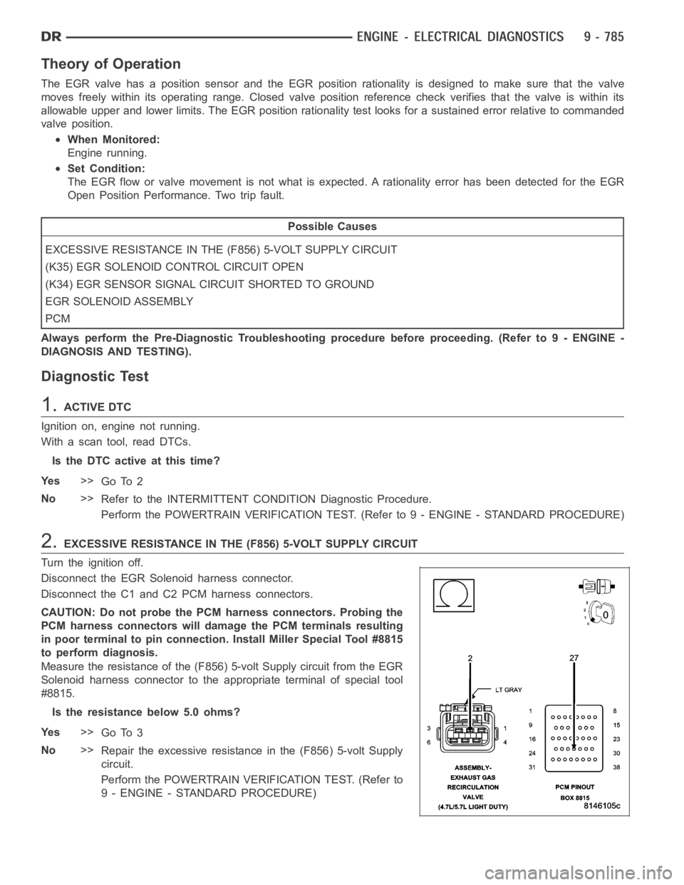
2.EXCESSIVE RESISTANCE IN THE (F856) 5-VOLT SUPPLY CIRCUIT
Turn the ignition off.
Disconnect the EGR Solenoid harness connector.
Disconnect the C1 and C2 PCM harness connectors.
CAUTION: Do not probe the PCM harness connectors. Probing the
PCM harness connectors will damage the PCM terminals resulting
in poor terminal to pin connection. Install Miller Special Tool #8815
to perform diagnosis.
Measure the resistance of the (F856) 5-volt Supply circuit from the EGR
Solenoid harness connector to the appropriate terminal of special tool
#8815.
Is the resistance below 5.0 ohms?
Ye s>>
Go To 3
No>>
Repair the excessive resistance in the (F856) 5-volt Supply
circuit.
Perform the POWERTRAIN VERIFICATION TEST. (Refer to
9 - ENGINE - STANDARD PROCEDURE)
Page 96 of 5267
6.PCM
NOTE: Before continuing, check the PCM harness connector terminals for corrosion, damage, or terminal
push out. Repair as necessary.
Using the schematics as a guide, inspect the wire harness and connectors. Pay particular attention to all Power and
Ground circuits.
Were there any problems found?
Ye s>>
Repair as necessary.
Perform the POWERTRAIN VERIFICATION TEST. (Refer to 9 - ENGINE - STANDARD PROCEDURE)
No>>
Replace and program the Powertrain Control Module per Service Information.
Perform the POWERTRAIN VERIFICATION TEST. (Refer to 9 - ENGINE - STANDARD PROCEDURE)