DODGE RAM SRT-10 2006 Service Repair Manual
RAM SRT-10 2006
DODGE
DODGE
https://www.carmanualsonline.info/img/12/56917/w960_56917-0.png
DODGE RAM SRT-10 2006 Service Repair Manual
Trending: length, headrest, cooling, oil viscosity, steering wheel adjustment, battery location, fold seats
Page 3351 of 5267
Monitor the MS Solenoid LED on the Transmission Simulator.
Did the MS Solenoid LED on the Transmission Simulator blink on and off?
Ye s>>
Replace the Transmission Solenoid/TRS Assembly per the Service Information.
Perform 45RFE/545RFE TRANSMISSION VERIFICATION TEST - VER 1. (Refer to 21- TRANSMIS-
SION/TRANSAXLE/AUTOMATIC - 45RFE/545RFE - STANDARD PROCEDURE)
No>>
Go To 3
3.TRANSMISSION SOLENOID/TRS ASSEMBLY
With the scan tool, continue to actuate the MS Solenoid for the period of 2 minutes with the Transmission Simulator
still connected.
After 2 minutes of actuation, with the scan tool, stop the actuation and check for transmission DTCs.
Did the DTC P2706 reset during the actuation test?
Ye s>>
Go To 4
No>> Perform 45RFE/545RFE TRANSMISSION VERIFICATION TEST - VER 1. (Refer to21 - TRANSMIS-
SION/TRANSAXLE/AUTOMATIC - 45RFE/545RFE - STANDARD PROCEDURE)
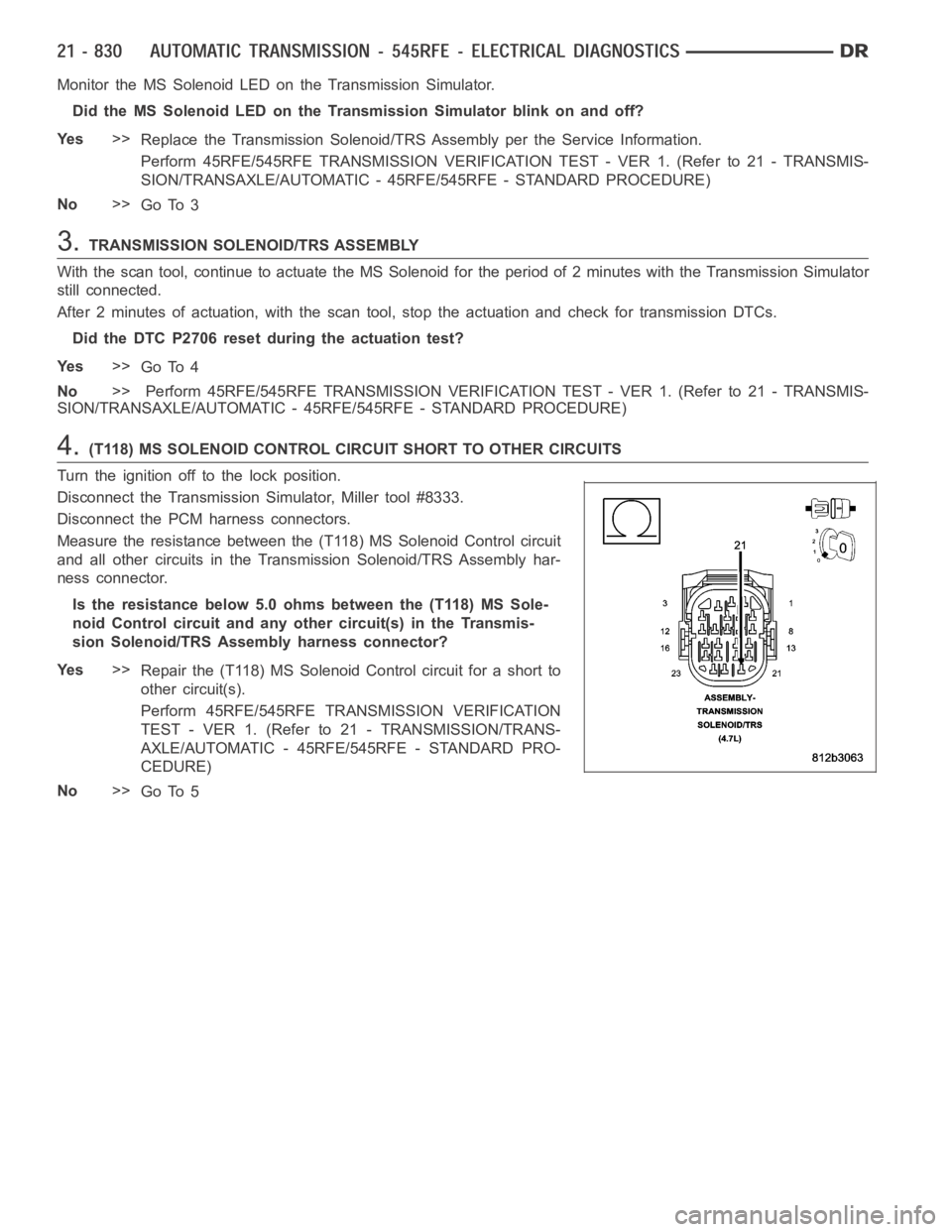
4.(T118) MS SOLENOID CONTROL CIRCUIT SHORT TO OTHER CIRCUITS
Turn the ignition off to the lock position.
Disconnect the Transmission Simulator, Miller tool #8333.
Disconnect the PCM harness connectors.
Measure the resistance between the (T118) MS Solenoid Control circuit
and all other circuits in the Transmission Solenoid/TRS Assembly har-
ness connector.
Is the resistance below 5.0 ohms between the (T118) MS Sole-
noid Control circuit and any other circuit(s) in the Transmis-
sion Solenoid/TRS Assembly harness connector?
Ye s>>
Repair the (T118) MS Solenoid Control circuit for a short to
other circuit(s).
Perform 45RFE/545RFE TRANSMISSION VERIFICATION
TEST - VER 1. (Refer to 21 - TRANSMISSION/TRANS-
AXLE/AUTOMATIC - 45RFE/545RFE - STANDARD PRO-
CEDURE)
No>>
Go To 5
Page 3352 of 5267
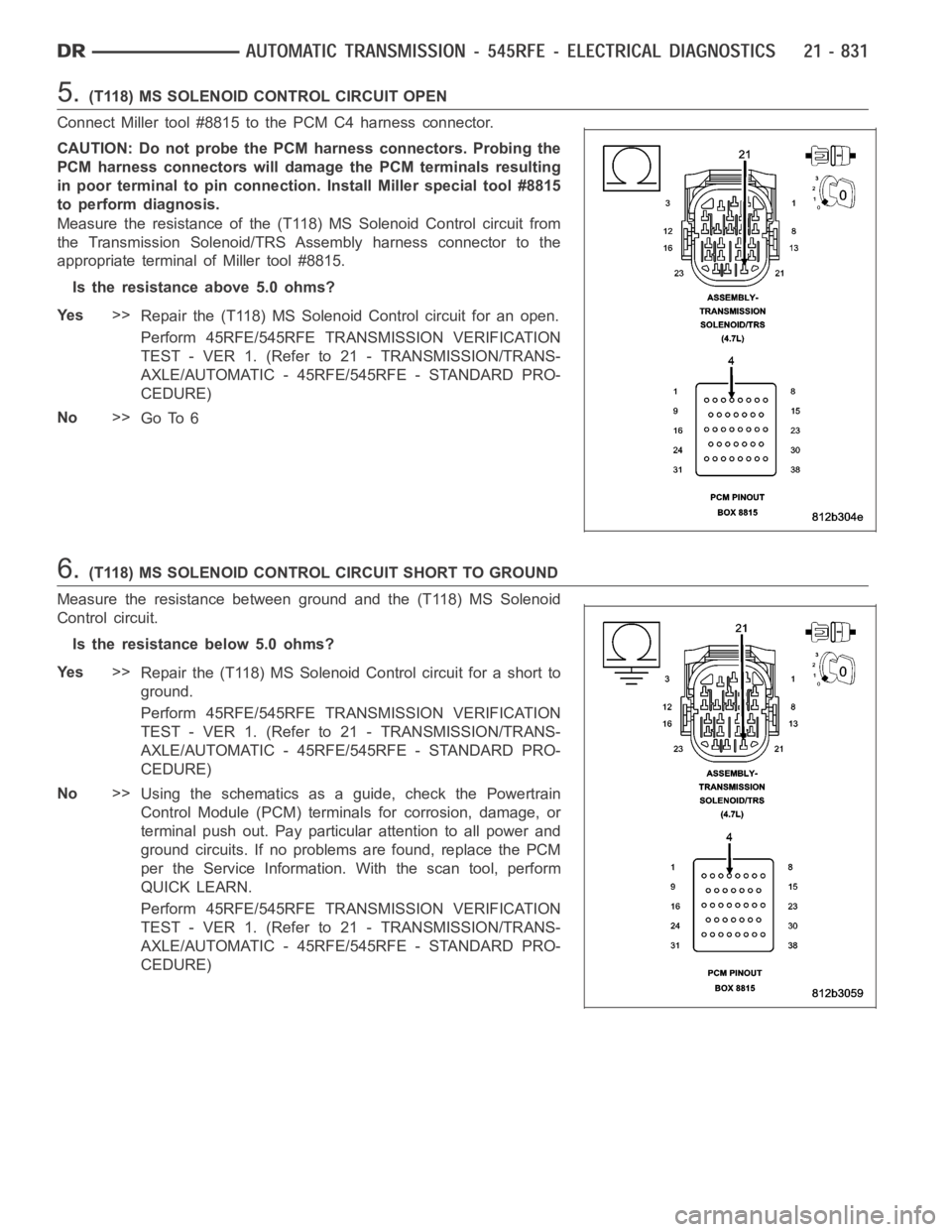
5.(T118) MS SOLENOID CONTROL CIRCUIT OPEN
Connect Miller tool #8815 to the PCM C4 harness connector.
CAUTION: Do not probe the PCM harness connectors. Probing the
PCM harness connectors will damage the PCM terminals resulting
in poor terminal to pin connection. Install Miller special tool #8815
to perform diagnosis.
Measure the resistance of the (T118) MS Solenoid Control circuit from
the Transmission Solenoid/TRS Assembly harness connector to the
appropriate terminal of Miller tool #8815.
Is the resistance above 5.0 ohms?
Ye s>>
Repair the (T118) MS Solenoid Control circuit for an open.
Perform 45RFE/545RFE TRANSMISSION VERIFICATION
TEST - VER 1. (Refer to 21 - TRANSMISSION/TRANS-
AXLE/AUTOMATIC - 45RFE/545RFE - STANDARD PRO-
CEDURE)
No>>
Go To 6
6.(T118) MS SOLENOID CONTROL CIRCUIT SHORT TO GROUND
Measure the resistance between ground and the (T118) MS Solenoid
Control circuit.
Is the resistance below 5.0 ohms?
Ye s>>
Repair the (T118) MS Solenoid Control circuit for a short to
ground.
Perform 45RFE/545RFE TRANSMISSION VERIFICATION
TEST - VER 1. (Refer to 21 - TRANSMISSION/TRANS-
AXLE/AUTOMATIC - 45RFE/545RFE - STANDARD PRO-
CEDURE)
No>>
Using the schematics as a guide, check the Powertrain
Control Module (PCM) terminals for corrosion, damage, or
terminal push out. Pay particular attention to all power and
ground circuits. If no problems are found, replace the PCM
per the Service Information.With the scan tool, perform
QUICK LEARN.
Perform 45RFE/545RFE TRANSMISSION VERIFICATION
TEST - VER 1. (Refer to 21 - TRANSMISSION/TRANS-
AXLE/AUTOMATIC - 45RFE/545RFE - STANDARD PRO-
CEDURE)
Page 3353 of 5267
U0002-CAN C BUS OFF PERFORMANCE
For a complete wiring diagramRefer to Section 8W.
Page 3354 of 5267
When Monitored:
Every 7 msec. Conditions: 1) Engine speed greater than 500 RPM. 2) Battery voltage greater than 10v but
less than 16v.
Set Condition:
CAN C bus messages not received for 10 seconds.
Theory of Operation
Some NGC controllers communicate with other controllers over the CAN C bus. The transmission controller contin-
uously monitors the bus activity and receives the messages it needs. The CAN C bus is also used to communicate
transmission MIL status to the Engine Controller, therefor if the Engine Controller is unable to communicate with the
Transmission Controller, the Engine Controller will light the MIL.
Diagnose the U0002 CAN C BUS OFF PERFORMANCE as the U0001 CAN C BUS CIRCUIT test in 8-ELEC-
TRICAL/ELECTRONIC CONTROL MODULES - DIAGNOSIS AND TESTING for diagnostic procedures and for
further possible causes.
Page 3355 of 5267
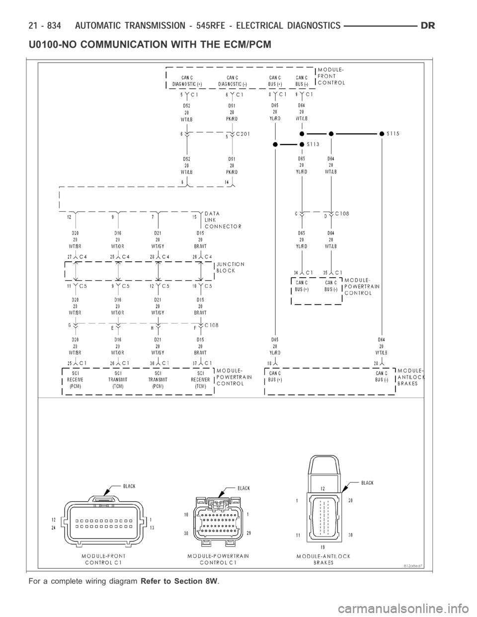
U0100-NO COMMUNICATION WITH THE ECM/PCM
For a complete wiring diagramRefer to Section 8W.
Page 3356 of 5267
When Monitored:
Every 7 msec. with the ignition on.
Set Condition:
ECM/PCM CAN bus message not received by the Transmission Control System for the period of 10 seconds.
Theory of Operation
Communication over the CAN bus is continuously monitored between the Engine Control System and the Trans-
mission Control System. Due to the integration of both systems into one module, (Powertrain Control Module) the
bus communication between the systems is internally transmitted over theduel port ram.
Refer to 8 - ELECTRICAL/ELECTRONIC CONTROL MODULES - DIAGNOSIS AND TESTING for diagnostic
procedures and for further possible causes.
Page 3357 of 5267
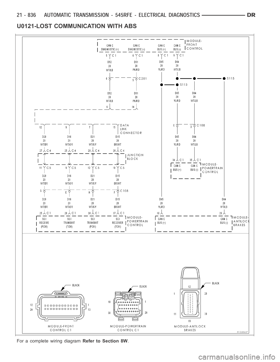
U0121-LOST COMMUNICATION WITH ABS
For a complete wiring diagramRefer to Section 8W.
Page 3358 of 5267
When Monitored:
Every 7 msec. Conditions: 1) Engine speed greater than 500 RPM. 2) Battery voltage greater than 10v but
less than 16v.
Set Condition:
CAN C bus messages not received for 10 seconds.
Theory of Operation
Some NGC controllers communicate with other controllers over the CAN C bus. The transmission controller contin-
uously monitors the bus activity and receives the messages it needs. The CAN C bus is also used to communicate
transmission MIL status to the Engine Controller, therefor if the Engine Controller is unable to communicate with the
Transmission Controller, the Engine Controller will light the MIL.
Refer to 8-ELECTRICAL/ELECTRONIC CONTROL MODULES - DIAGNOSIS AND TESTING for diagnostic pro-
cedures and for further possible causes.
Page 3359 of 5267
U0141 LOST COMMUNICATION WITH FCM
For a complete wiring diagramRefer to Section 8W.
Page 3360 of 5267
When Monitored:
Every 7 msec. Conditions: 1) Engine speed greater than 500 RPM. 2) Battery voltage greater than 10v but
less than 16v.
Set Condition:
CAN C bus messages not received for 10 seconds.
Theory of Operation
Some NGC controllers communicate with other controllers over the CAN C bus. The transmission controller contin-
uously monitors the bus activity and receives the messages it needs. The CAN C bus is also used to communicate
transmission MIL status to the Engine Controller, therefor if the Engine Controller is unable to communicate with the
Transmission Controller, the Engine Controller will light the MIL.
Refer to 8-ELECTRICAL/ELECTRONIC CONTROL MODULES - DIAGNOSIS AND TESTING for diagnostic pro-
cedures and for further possible causes.
STANDARD PROCEDURE
Trending: wiring diagram, valve train, ECU, wheel bolts, radiator, ignition, transmission


