DODGE RAM SRT-10 2006 Service Repair Manual
RAM SRT-10 2006
DODGE
DODGE
https://www.carmanualsonline.info/img/12/56917/w960_56917-0.png
DODGE RAM SRT-10 2006 Service Repair Manual
Trending: air filter, phone, jump start terminals, tires, heating, child restraint, radiator
Page 4691 of 5267
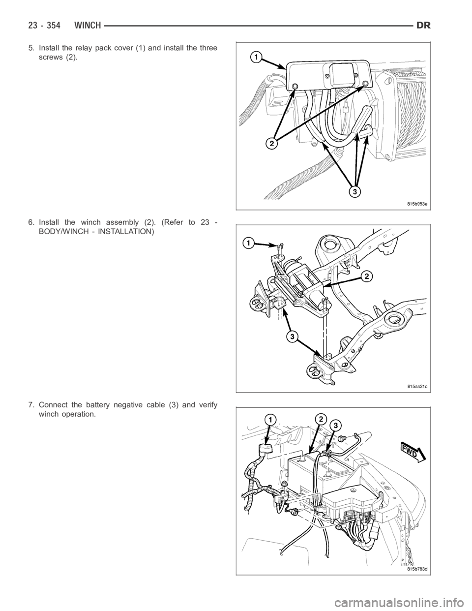
5. Install the relay pack cover (1) and install the three
screws (2).
6. Install the winch assembly (2). (Refer to 23 -
BODY/WINCH - INSTALLATION)
7. Connect the battery negative cable (3) and verify
winch operation.
Page 4692 of 5267
WIRE ROPE
REMOVAL
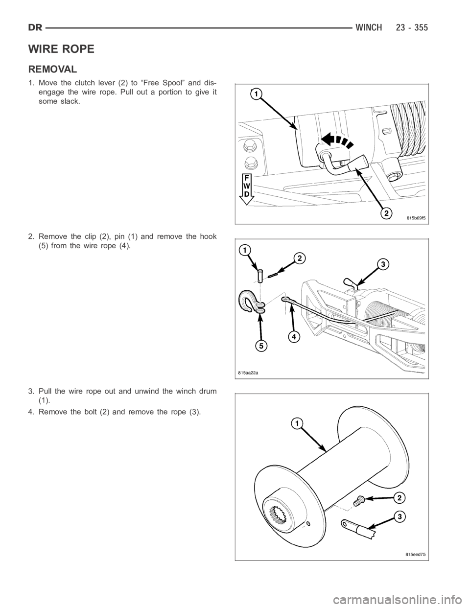
1. Move the clutch lever (2) to “Free Spool” and dis-
engage the wire rope. Pull out a portion to give it
some slack.
2. Remove the clip (2), pin (1) and remove the hook
(5) from the wire rope (4).
3. Pull the wire rope out and unwind the winch drum
(1).
4. Remove the bolt (2) and remove the rope (3).
Page 4693 of 5267
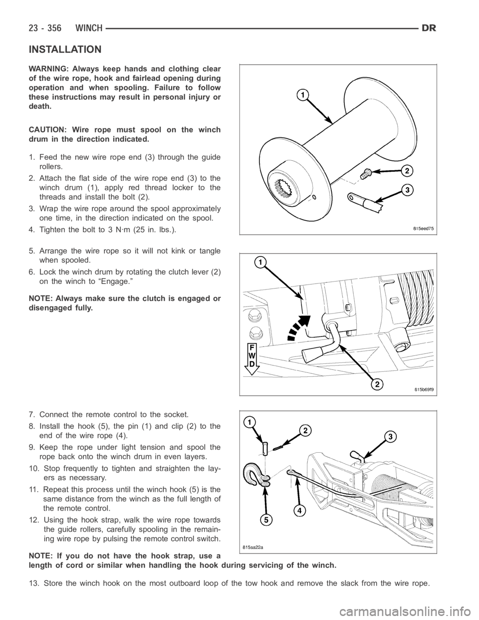
INSTALLATION
WARNING: Always keep hands and clothing clear
of the wire rope, hook and fairlead opening during
operation and when spooling. Failure to follow
these instructions may result in personal injury or
death.
CAUTION: Wire rope must spool on the winch
drum in the direction indicated.
1. Feed the new wire rope end (3) through the guide
rollers.
2. Attach the flat side of the wire rope end (3) to the
winch drum (1), apply red thread locker to the
threads and install the bolt (2).
3. Wrap the wire rope around the spool approximately
one time, in the direction indicated on the spool.
4. Tighten the bolt to 3 Nꞏm (25 in. lbs.).
5. Arrange the wire rope so it will not kink or tangle
when spooled.
6. Lock the winch drum by rotating the clutch lever (2)
on the winch to “Engage.”
NOTE: Always make sure the clutch is engaged or
disengaged fully.
7. Connect the remote control to the socket.
8. Install the hook (5), the pin (1) and clip (2) to the
end of the wire rope (4).
9. Keep the rope under light tension and spool the
rope back onto the winch drum in even layers.
10. Stop frequently to tighten and straighten the lay-
ers as necessary.
11. Repeat this process until the winch hook (5) is the
same distance from the winch as the full length of
theremotecontrol.
12. Using the hook strap, walk the wire rope towards
the guide rollers, carefully spooling in the remain-
ing wire rope by pulsing the remote control switch.
NOTE: If you do not have the hook strap, use a
length of cord or similar when handling the hook during servicing of the winch.
13. Store the winch hook on the most outboard loop of the tow hook and remove the slack from the wire rope.
Page 4694 of 5267
WIRE ROPE GUIDE ROLLERS
REMOVAL
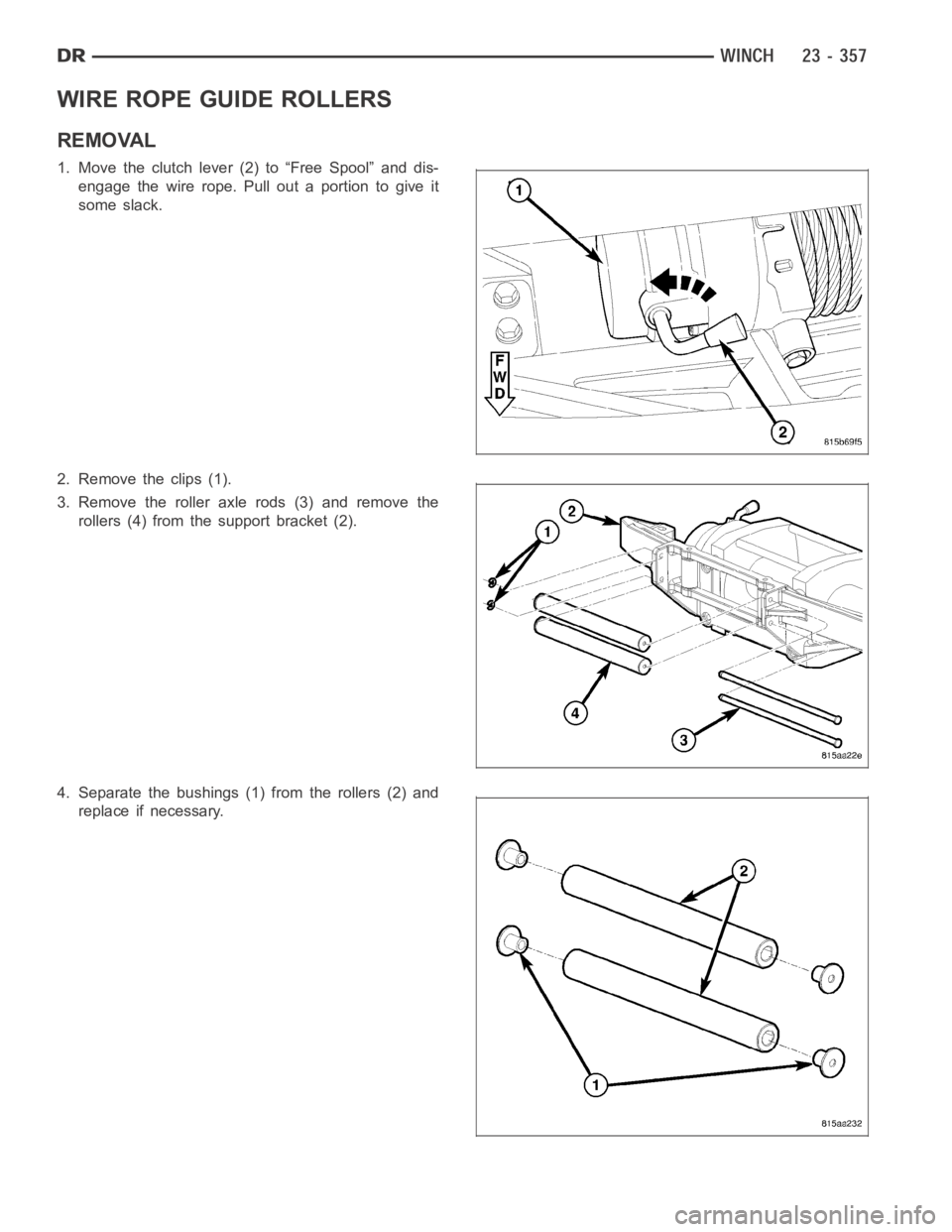
1. Move the clutch lever (2) to “Free Spool” and dis-
engage the wire rope. Pull out a portion to give it
some slack.
2. Remove the clips (1).
3. Remove the roller axle rods (3) and remove the
rollers (4) from the support bracket (2).
4. Separate the bushings (1) from the rollers (2) and
replace if necessary.
Page 4695 of 5267
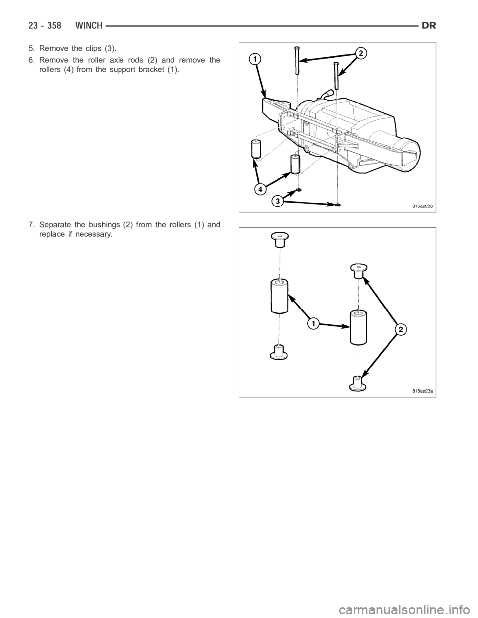
5. Remove the clips (3).
6. Remove the roller axle rods (2) and remove the
rollers (4) from the support bracket (1).
7. Separate the bushings (2) from the rollers (1) and
replace if necessary.
Page 4696 of 5267
INSTALLATION
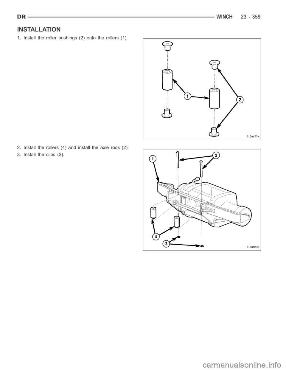
1. Install the roller bushings (2) onto the rollers (1).
2. Install the rollers (4) and install the axle rods (2).
3. Install the clips (3).
Page 4697 of 5267
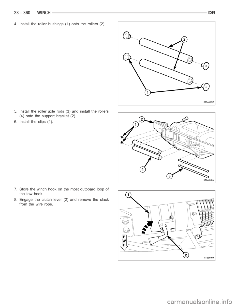
4. Install the roller bushings (1) onto the rollers (2).
5. Install the roller axle rods (3) and install the rollers
(4) onto the support bracket (2).
6. Install the clips (1).
7. Store the winch hook on the most outboard loop of
the tow hook.
8. Engage the clutch lever (2) and remove the slack
fromthewirerope.
Page 4698 of 5267
page page
GAP AND FLUSH
SPECIFICATIONS ............................ 362
OPENING DIMENSIONS
SPECIFICATIONS ............................ 367
SEALER LOCATIONS
SPECIFICATIONS ............................ 370STRUCTURAL ADHESIVE LOCATIONS
SPECIFICATIONS ............................ 387
WELD LOCATIONS
SPECIFICATIONS ............................ 395
Page 4699 of 5267
GAP AND FLUSH
SPECIFICATIONS
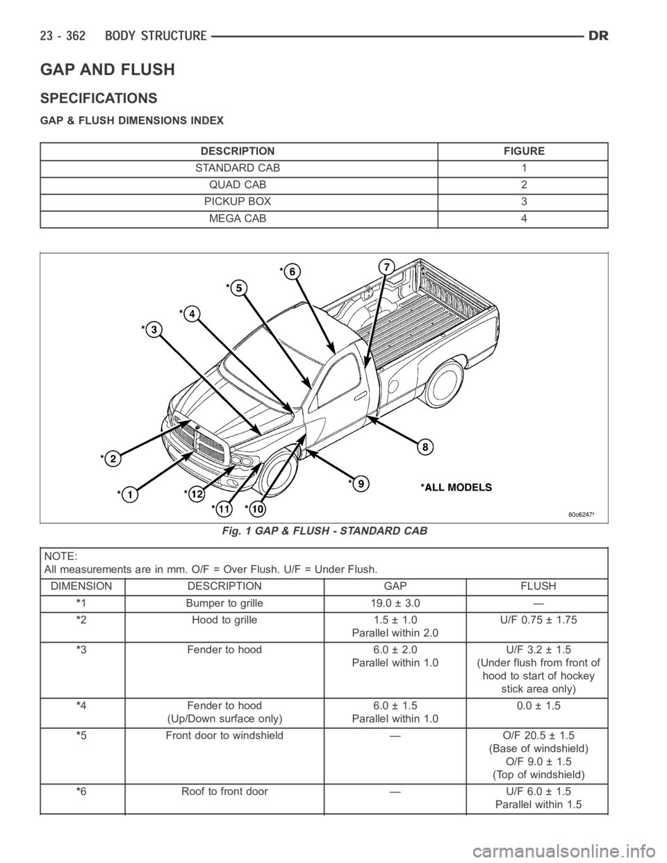
GAP & FLUSH DIMENSIONS INDEX
DESCRIPTION FIGURE
STANDARD CAB 1
QUAD CAB 2
PICKUP BOX 3
MEGA CAB 4
NOTE:
All measurements are in mm. O/F = Over Flush. U/F = Under Flush.
DIMENSION DESCRIPTION GAP FLUSH
*1 Bumper to grille 19.0 ± 3.0 —
*2 Hood to grille 1.5 ± 1.0
Parallel within 2.0U/F 0.75 ± 1.75
*3 Fender to hood 6.0 ± 2.0
Parallel within 1.0U/F 3.2 ± 1.5
(Under flush from front of
hood to start of hockey
stick area only)
*4 Fender to hood
(Up/Down surface only)6.0 ± 1.5
Parallel within 1.00.0 ± 1.5
*5 Front door to windshield — O/F 20.5 ± 1.5
(Base of windshield)
O/F 9.0 ± 1.5
(Top of windshield)
*6 Roof to front door — U/F 6.0 ± 1.5
Parallel within 1.5
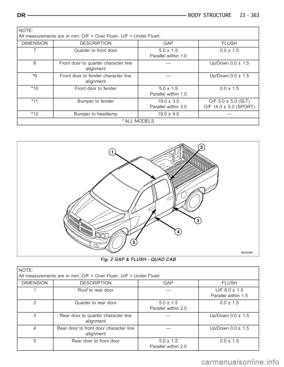
Fig. 1 GAP & FLUSH - STANDARD CAB
Page 4700 of 5267
NOTE:
All measurements are in mm. O/F = Over Flush. U/F = Under Flush.
DIMENSION DESCRIPTION GAP FLUSH
7 Quarter to front door 5.0 ± 1.5
Parallel within 1.00.0 ± 1.5
8 Front door to quarter character line
alignment— Up/Down 0.0 ± 1.5
*9 Front door to fender character line
alignment— Up/Down 0.0 ± 1.5
*10 Front door to fender 5.0 ± 1.5
Parallel within 1.00.0 ± 1.5
*11 Bumper to fender 19.0 ± 3.0
Parallel within 3.0O/F 5.0 ± 5.0 (SLT)
O/F 14.0 ± 5.0 (SPORT)
*12 Bumper to headlamp 19.0 ± 4.0 —
*ALLMODELS
NOTE:
All measurements are in mm. O/F = Over Flush. U/F = Under Flush.
DIMENSION DESCRIPTION GAP FLUSH
1 Roof to rear door — U/F 6.0 ± 1.5
Parallel within 1.5
2 Quarter to rear door 5.0 ± 1.5
Parallel within 2.00.0 ± 1.5
3 Rear door to quarter character line
alignment— Up/Down 0.0 ± 1.5
4 Rear door to front door character line
alignment— Up/Down 0.0 ± 1.5
5 Rear door to front door 5.0 ± 1.5
Parallel within 2.00.0 ± 1.5
Fig. 2 GAP & FLUSH - QUAD CAB
Trending: air condition, instrument cluster, child restraint, low oil pressure, oil temperature, seats, height
