DODGE SPRINTER 2007 2.G Owners Manual
Manufacturer: DODGE, Model Year: 2007, Model line: SPRINTER, Model: DODGE SPRINTER 2007 2.GPages: 393, PDF Size: 7.61 MB
Page 151 of 393
150 Controls in detailDriving systems
3
Parktronic is an electronic parking aid and
informs you visually and audibly of the dis-
tance between the vehicle and an obsta-
cle.
Parktronic is automatically switched on
when you switch on the ignition and re-
lease the handbrake. You must also move
the selector lever to position D, N or R.
Parktronic switches off at speeds of over
11 mph (18 km/h). Parktronic switches on
again as soon as the vehicle’s speed falls
below this limit speed.
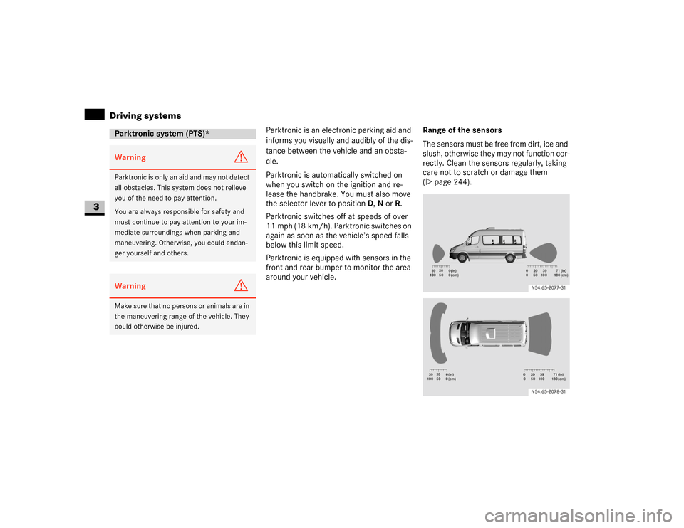
Parktronic is equipped with sensors in the
front and rear bumper to monitor the area
around your vehicle.Range of the sensors
The sensors must be free from dirt, ice and
slush, otherwise they may not function cor-
rectly. Clean the sensors regularly, taking
care not to scratch or damage them
(\2page 244).
Parktronic system (PTS)*Warning
G
Parktronic is only an aid and may not detect
all obstacles. This system does not relieve
you of the need to pay attention.
You are always responsible for safety and
must continue to pay attention to your im-
mediate surroundings when parking and
maneuvering. Otherwise, you could endan-
ger yourself and others.Warning
G
Make sure that no persons or animals are in
the maneuvering range of the vehicle. They
could otherwise be injured.
Page 152 of 393
151 Controls in detail
Driving systems
3
Front sensors
Rear sensors
Minimum distance
If an obstacle is within this range, all seg-
ments of the warning displays light up and
you will hear an audible warning tone. The
distance may no longer be displayed if you
drive the vehicle closer to the obstacle
than the minimum distance.Warning displays
The warning displays indicate the distance
between the sensor and the obstacle.
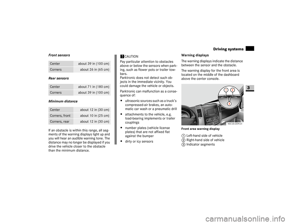
The warning display for the front area is
located on the middle of the dashboard
above the center console.
Front area warning display1Left-hand side of vehicle
2Right-hand side of vehicle
3Indicator segments
Center
about 39 in (100 cm)
Corners
about 26 in (65 cm)
Center
about 71 in (180 cm)
Corners
about 39 in (100 cm)
Center
about 12 in (30 cm)
Corners, front
about 10 in (25 cm)
Corners, rear
about 12 in (30 cm)
!
CAUTION
Pay particular attention to obstacles
above or below the sensors when park-
ing, such as flower pots or trailer tow-
bars.
Parktronic does not detect such ob-
jects in the immediate vicinity. You
could damage the vehicle or objects.
Parktronic can malfunction as a conse-
quence of:
\4ultrasonic sources such as a truck’s
compressed-air brakes, an auto-
matic car wash or a pneumatic drill
\4attachments to the vehicle, e.g.
load-bearing implements or trailer
couplings
\4number plates (vehicle license
plates) that are not affixed flat
against the bumper
\4dirty or icy sensors
N54.65-2074-31
Page 153 of 393
152 Controls in detailDriving systems
3
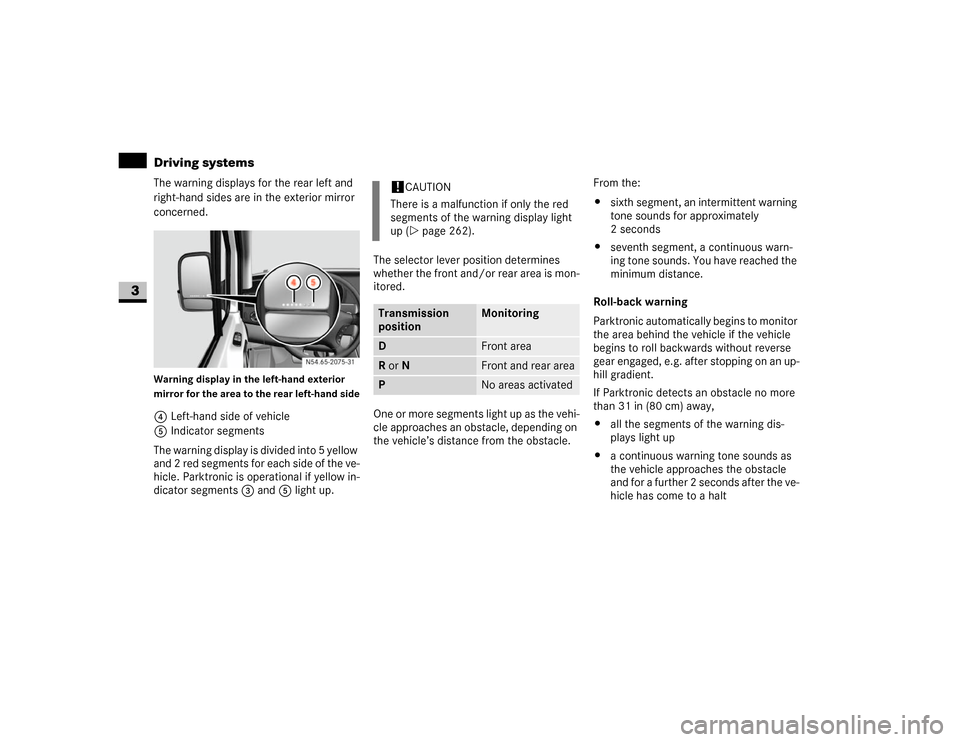
The warning displays for the rear left and
right-hand sides are in the exterior mirror
concerned.Warning display in the left-hand exterior
mirror for the area to the rear left-hand side4Left-hand side of vehicle
5Indicator segments
The warning display is divided into 5 yellow
and 2 red segments for each side of the ve-
hicle. Parktronic is operational if yellow in-
dicator segments3 and5 light up.The selector lever position determines
whether the front and/or rear area is mon-
itored.
One or more segments light up as the vehi-
cle approaches an obstacle, depending on
the vehicle’s distance from the obstacle.From the:
\4sixth segment, an intermittent warning
tone sounds for approximately
2seconds
\4seventh segment, a continuous warn-
ing tone sounds. You have reached the
minimum distance.
Roll-back warning
Parktronic automatically begins to monitor
the area behind the vehicle if the vehicle
begins to roll backwards without reverse
gear engaged, e.g. after stopping on an up-
hill gradient.
If Parktronic detects an obstacle no more
than 31 in (80 cm) away,
\4all the segments of the warning dis-
plays light up
\4a continuous warning tone sounds as
the vehicle approaches the obstacle
and for a further 2 seconds after the ve-
hicle has come to a halt N54.65-2075-31
!
CAUTION
There is a malfunction if only the red
segments of the warning display light
up (\2page 262).
Transmission
position
Monitoring
D
Front area
R or N
Front and rear area
P
No areas activated
Page 154 of 393
153 Controls in detail
Driving systems
3
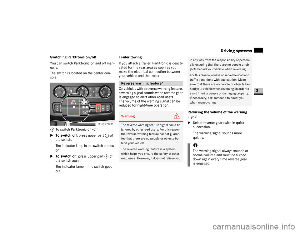
Switching Parktronic on/off
You can switch Parktronic on and off man-
ually.
The switch is located on the center con-
sole.
1To switch Parktronic on/off
\1To switch off: press upper part 1 of
the switch.
The indicator lamp in the switch comes
on.
\1To switch on: press upper part 1 of
the switch again.
The indicator lamp in the switch goes
out.Trailer towing
If you attach a trailer, Parktronic is deacti-
vated for the rear area as soon as you
make the electrical connection between
your vehicle and the trailer.
On vehicles with a reverse warning feature,
a warning signal sounds when reverse gear
is engaged to alert other road users.
The volume of the warning signal can be
reduced for night-time operation.
Reducing the volume of the warning
signal
\1Select reverse gear twice in quick
succession.
The warning signal sounds more
quietly. N54.25-2922-31
Reverse warning feature*Warning
G
The reverse warning feature signal could be
ignored by other road users. For this reason,
the reverse warning feature cannot guaran-
tee that there are no people or objects be-
hind your vehicle.
The reverse warning feature is a system
which helps you ensure the safety of other
road users. However, it does not relieve you
in any way from the responsibility of person-
ally ensuring that there are no people or ob-
jects behind your vehicle when reversing.
For this reason, always observe the road and
traffic conditions with due caution. Make
sure that there are no people or objects be-
hind your vehicle when reversing, in order to
avoid injuring people or damaging property.
If necessary, ask someone to direct you
when maneuvering.iThe warning signal always sounds at
normal volume and must be turned
down again every time reverse gear
is engaged.
Page 155 of 393
154 Controls in detailOperating the vehicle
3
\3 Operating the vehicleWhen activated, the operating speed gov-
ernor (ADR) automatically increases the
engine speed to a preset or adjustable
operating speed (\2page 155).Activating / deactivating ADR
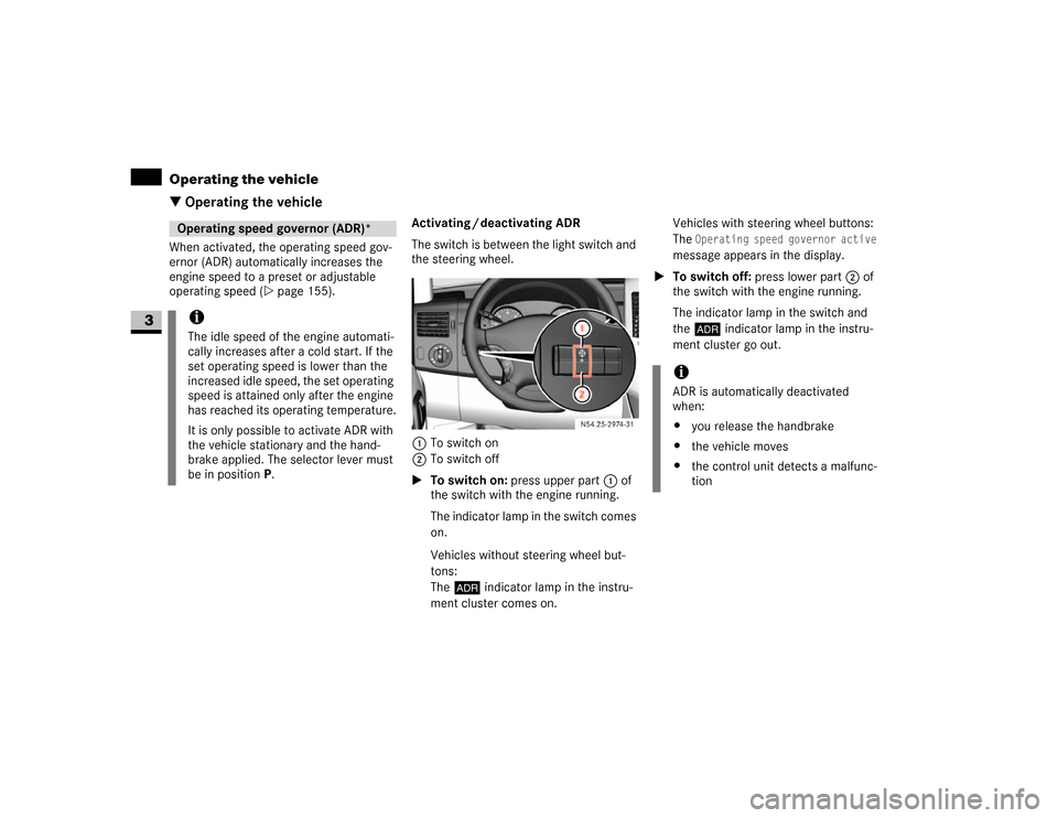
The switch is between the light switch and
the steering wheel.
1To switch on
2To switch off
\1To switch on: press upper part 1 of
the switch with the engine running.
The indicator lamp in the switch comes
on.
Vehicles without steering wheel but-
tons:
The™ indicator lamp in the instru-
ment cluster comes on.Vehicles with steering wheel buttons:
The
Operating speed governor active
message appears in the display.
\1To switch off: press lower part 2 of
the switch with the engine running.
The indicator lamp in the switch and
the™ indicator lamp in the instru-
ment cluster go out.
Operating speed governor (ADR)*iThe idle speed of the engine automati-
cally increases after a cold start. If the
set operating speed is lower than the
increased idle speed, the set operating
speed is attained only after the engine
has reached its operating temperature.
It is only possible to activate ADR with
the vehicle stationary and the hand-
brake applied. The selector lever must
be in position P.
N54.25-2932-31
iADR is automatically deactivated
when:
\4you release the handbrake
\4the vehicle moves
\4the control unit detects a malfunc-
tion
Page 156 of 393
155 Controls in detail
Operating the vehicle
3
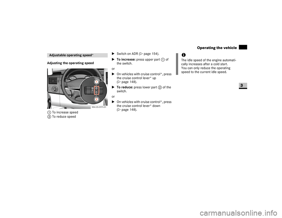
Adjusting the operating speed
1To increase speed
2To reduce speed\1Switch on ADR (\2page 154).
\1To increase: press upper part 1 of
the switch.
or
\1On vehicles with cruise control*, press
the cruise control lever* up
(\2page 148).
\1To reduce: press lower part 2 of the
switch.
or
\1On vehicles with cruise control*, press
the cruise control lever* down
(\2page 148).Adjustable operating speed*
N54.25-2933-31
iThe idle speed of the engine automati-
cally increases after a cold start.
You can only reduce the operating
speed to the current idle speed.
Page 157 of 393
156 Controls in detailTransporting
3
\3 Transporting
For more information about the maximum
roof load and roof carrier systems, please
refer to the "Technical data" section
(\2page 351).
Loading guidelinesWarning
G
Secure and position a load as described in
the loading guidelines. Otherwise, the load
could slide or be thrown around in the event
of strong braking maneuvers, sudden chang-
es of direction or poor road conditions,
thereby injuring you or others. The same ap-
plies to dismantled seats if left inside the ve-
hicle.
Please note that loads increase the risk of
injury during an accident even if you comply
with all loading guidelines.
Observe the notes in the "Securing a load"
section (\2page 158).Warning
G
Do not exceed the vehicle's permissible
gross weight or the permissible axle loads
when loading the vehicle or carrying addi-
tional passengers.
If you exceed the vehicle's permissible axle
loads or the maximum permissible gross
weight when transporting items or carrying
passengers, tire stability and driving safety
are reduced. The vehicle's driving and steer-
ing characteristics would be greatly altered.
Braking and stopping distances would
be significantly longer.
Your vehicle's driving, steering and braking
characteristics change as the vehicle's
gross weight increases or its center of grav-
ity is raised.
Always ensure that loads are distributed
correctly and adapt your driving style in ac-
cordance with the load.Warning
G
After an accident, have a damaged load
compartment floor or damaged load sur-
face, the lashing eyes and lashing materials
inspected by a specialist workshop having
the necessary technical expertise and tools
to carry out the required work.
The manufacturer recommends that you use
an authorized Sprinter Dealer for this pur-
pose. In particular, work relevant to safety
or on safety-related systems must be car-
ried out at a qualified specialist workshop. !
CAUTION
If you are using a roof carrier system,
observe the maximum roof load and
maximum load-bearing capacity of the
roof carrier system.
Page 158 of 393
157 Controls in detail
Transporting
3
Before loading
\1Check the tire pressures and correct
them if necessary (\2page 213).
\1Clean the load compartment floor.
The load compartment floor must be
dry, cleanly swept and free of oil and
dust to reduce the risk of the load slip-
ping.
\1If necessary, place anti-slip mats on the
load compartment floor.During loading
\1Observe the maximum permissible axle
loads and permissible gross weight for
the vehicle.
\1Observe the notes on load distribution
(\2page 158).
\1Secure the load (\2page 158). All
country-specific legal requirements
must be observed.Checks after loading
\1Securing a load: before each journey
and at regular intervals during longer
journeys, check whether the load is
properly secured and take additional
securing measures, if necessary.
\1Doors: close the sliding doors and rear
doors.
\1Tire pressure: adjust the tire pressure
in accordance with the vehicle's load
(\2page 213).
\1Driving characteristics: adapt your
driving style to the load.
!
CAUTION
As soon as the anti-slip mats start to
show signs of permanent deformation,
squashed areas or tears/holes, they
are unsuitable for securing loads and
must be replaced.
!
CAUTION
In passenger vans with the maximum
number of seats, the maximum payload
would cause the permissible rear axle
load to be exceeded.
iBear in mind that your vehicle's unlad-
en weight is increased by the installa-
tion of optional equipment and
accessories.
Warning
G
Make sure that the sliding doors and rear
doors are always closed when the engine is
running.
Otherwise, exhaust fumes could enter the
vehicle interior and poison you.
Page 159 of 393
158 Controls in detailTransporting
3
The load's overall center of gravity should
be as low and central as possible, between
the axles near the rear axle.
For crewbus models:
\1Always transport loads in the load com-
partment.
\1Always place loads flush against the
seat backrests of the rear bench seat.
\1Slide larger and heavier loads as far for-
ward as possible when looking in the
direction of travel. Stack items against
each other behind the rear bench seat.\1Always secure loads with suitable
transport aids or lashing materials.
As the driver of the vehicle, you are respon-
sible for ensuring that the load is secured
against slipping, tipping over, rolling or fall-
ing down, whether driving in normal traffic
situations or on poor road surfaces or as a
result of having to swerve to avoid an ob-
stacle or applying the brakes fully.Failing to secure the load in accordance
with relevant requirements and sound
practice may be a punishable offense, de-
pending on national legislation and the
consequences that arise.
For this reason, observe the legal require-
ments in all countries concerned.
Before each journey and at regular inter-
vals during longer journeys, check whether
the load is secure and take additional ac-
tion to improve any incorrect or inade-
quate safety measures.
\1Fill up any empty spaces between the
load and the load compartment walls
or wheel arches in a form-fitting man-
ner. For this purpose, use solid trans-
port aids, such as chocks, wooden
blocks or storage cushions.Load distribution!
CAUTION
Excessive loads on individual points of
the load compartment floor or load sur-
face have a negative effect on handling
characteristics and could damage the
floor covering.
iObserve the following notes:
\4Do not stack loads higher than the
upper edge of the backrests.
\4Transport loads behind seats that
are not occupied.
\4If the rear bench seat is not occu-
pied, insert the seat belts in a cross-
wise pattern into the opposite belt
buckles.Securing a load
iInformation about how to secure a
load correctly can be obtained from the
manufacturers of transport aids or
lashing materials for securing loads.
Page 160 of 393
159 Controls in detail
Transporting
3
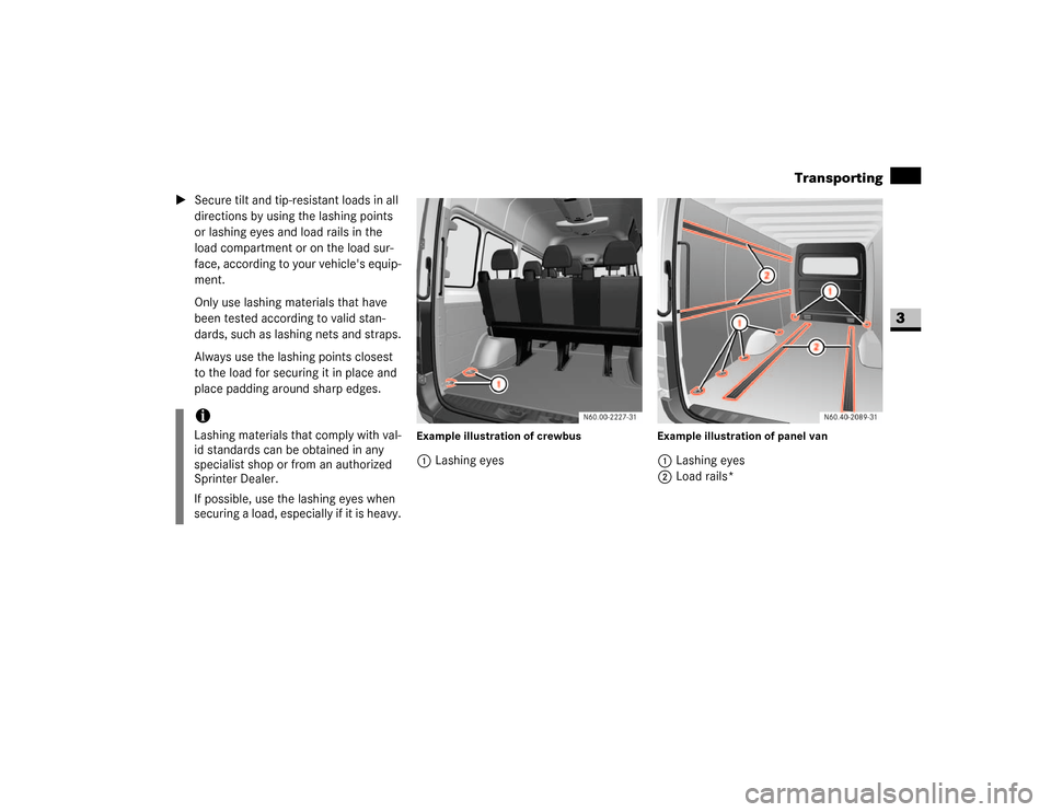
\1Secure tilt and tip-resistant loads in all
directions by using the lashing points
or lashing eyes and load rails in the
load compartment or on the load sur-
face, according to your vehicle's equip-
ment.
Only use lashing materials that have
been tested according to valid stan-
dards, such as lashing nets and straps.
Always use the lashing points closest
to the load for securing it in place and
place padding around sharp edges.
Example illustration of crewbus1Lashing eyes
Example illustration of panel van1Lashing eyes
2Load rails*
iLashing materials that comply with val-
id standards can be obtained in any
specialist shop or from an authorized
Sprinter Dealer.
If possible, use the lashing eyes when
securing a load, especially if it is heavy.