DODGE STRATUS COUPE 2005 2.G Owners Manual
Manufacturer: DODGE, Model Year: 2005, Model line: STRATUS COUPE, Model: DODGE STRATUS COUPE 2005 2.GPages: 396
Page 341 of 396

one mile (1.6 km) after being stationary for three hours.
Cold inflation pressure must not exceed the maximum
values molded into the tire sidewall. After driving several
miles, tire inflation pressure may increase 2 to 6 psi (14 to 41
kPa) over the cold inflation pressure; do NOT let air out of
the tires to match the specified cold pressure, or your tires
will be underinflated.
Check your tires each time you refuel. If one tire looks lower
than the others, check the tire inflation pressure for all of
them. The following precautions also should be observed:
1. Keep your tires inflated to the pressures that are
recommended. (See the tire and loading information
placard attached the driver's side ``B''-Pillar.)
2. Stay within the load limits that are recommended.
3. Make sure that the weight of your vehicle load is
evenly distributed.
4. Drive at safe speeds.
5. After the tire inflation pressure has been adjusted,
check the tires for damage and air leaks. Be sure to
replace the rubber caps on the valve stems.
Radial ply tires
Radial ply tires provide improved tread life, road hazard
resistance and smoother high speed ride. The radial ply
factory-installed tires on this vehicle are of belted con-
struction and are selected to complement the ride and
handling characteristics of your vehicle.
Radial ply tires have the same load carrying capacity as
bias or bias-belted tires of the same letter size, and use the
same recommended inflation pressures.
Mixing of radial ply tires with bias or bias-belted tires is
not recommended. Combining radial ply and bias or
bias-belted tires on one vehicle will negatively affect
vehicle handling. It is recommended that radial ply tires
should always be used as a set of four.
As longer wearing tires can be more susceptible to
irregular tread wear, it is very important to follow the tire
rotation interval shown in the section ªTire rotationº to
achieve full tread life potential in these tires.
Cuts and punctures in radial ply tires are repairable only
in the tread area, because of sidewall flexing. Consult
your tire dealer for radial ply tire repairs.
MAINTENANCE 341
9
Page 342 of 396
Tire pressure for sustained high-speed driving
For sustained high-speed driving, increase inflation pres-
sure 4 psi (28 kPa) above the recommended pressure but
do not exceed the maximum cold inflation pressure
molded into the tire sidewall.
Replacing tire and wheels
CAUTION!
²Avoid using different size tires from the one listed
and the combined use of different types of tires,
as this can affect driving safety.
Refer to the(TIRES AND WHEELS(on page 377.
²Even if a wheel has the same rim size and offset as
the specified type of wheel, its shape may prevent
it from being fitted correctly. Consult an autho-
rized dealer before using wheels that you have.
Tire maintenance
The following maintenance steps are recommended:
1. Check pressure regularly.
2. Maintain wheel balance and front suspension align-
ment.3. Rotate tires regularly in accordance with the recom-
mendation in the section ªTire rotationº on page 347.
Loading information
WARNING!
Overloading of your tire is dangerous. Overloading can
cause tire failure, affect vehicle handling, and increase
your stopping distance. Use tires of the recommended
load capacity for your vehicle. Never overload them.
It is important to familiarize yourself with the following
terms before loading your vehicle:
²Vehicle maximum load on the tire : load on an indi-
vidual tire that is determined by distributing to each
axle its share of the maximum loaded vehicle weight
and dividing by two.
342 MAINTENANCE
Page 343 of 396

²Vehicle normal load on the tire : load on an individual
tire that is determined by distributing to each axle its
share of the curb weight, accessory weight, and nor-
mal occupant weight and dividing by two.
²Maximum loaded vehicle weight : the sum of ±
(a) Curb weight;
(b) Accessory weight:
(c) Vehicle capacity weight; and
(d) Production options weight.
²Curb weight : the weight of a motor vehicle with
standard equipment including the maximum capacity
of fuel, oil, and coolant, and, if so equipped, air
conditioning and additional weight optional engine.
²Accessory weight : the combined weight (in excess of
those standard items which may be replaced) of auto-
matic transmission, power steering, power brakes,
power windows, power seats, radio, and heater, to the
extent that these items are available as factory-
installed equipment (whether installed or not).
²Vehicle capacity weight : the rated cargo and luggage
load plus 150 lbs (68kg) times the vehicle's designated
seating capacity.
²Production options weight : the combined weight of
those installed regular production options weighing
over 5 lbs (2.3kg) in excess of those standard items
which they replace, not previously considered in curb
weight or accessory weight, including heavy duty
brakes, ride levelers, roof rack, heavy duty battery, and
special trim.
²Normal occupant weight : 150 lbs (68kg) times the
number of specified occupants. (In your vehicle the
number is 3).
²Occupant distribution : distribution of occupants in a
vehicle as specified. (In your vehicle the distribution is
2 in front, 1 in second seat).
Steps for Determining Correct Load Limit
1. Locate the statement9The combined weight of occu-
pants and cargo should never exceed XXX pounds9on
your vehicle's placard.
MAINTENANCE 343
9
Page 344 of 396

2. Determine the combined weight of the driver and
passengers that will be riding in your vehicle.
3. Subtract the combined weight of the driver and pas-
sengers from XXX kilograms or XXX pounds.
4. The resulting figure equals the available amount of
cargo and luggage load capacity. For example, if the
9XXX9amount equals 1400 lbs. and there will be five 150
lb. passengers in your vehicle, the amount of available
cargo and luggage load capacity is 650 lbs. (1400-750 (5 x
150) = 650 lbs.)
5. Determine the combined weight of luggage and cargo
being loaded on the vehicle. That weight may not safely
exceed the available cargo and luggage load capacity
calculated in Step 4.
6. If your vehicle will be towing a trailer, load from your
trailer will be transferred to your vehicle. Consult this
manual to determine how this reduces the available
cargo and luggage load capacity of your vehicle.
NOTE: The above steps for determining correct load
limit were written in accordance with U.S.A. regulations.
Your vehicle cannot tow a trailer, so step 6 is irrelevant.
NOTE:
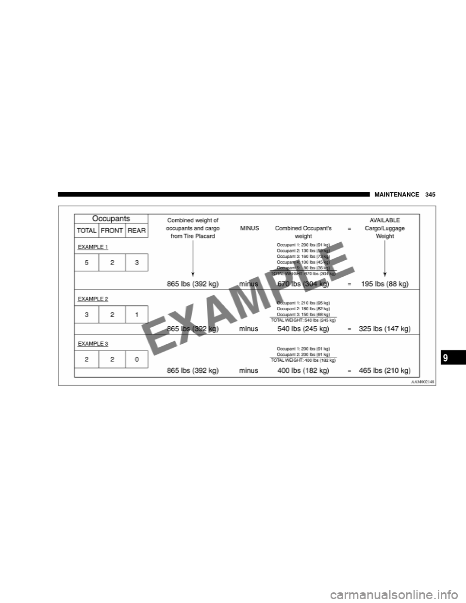
(1) The following table shows examples on how to
calculate total cargo/load capacity of your vehicle with
varying seating configurations and number and size of
occupants. This table is for illustration purposes only and
may not be accurate for the seating and load capacity of
your vehicle.
(2) For the following example the combined weight of
occupants and cargo should never exceed 865 lbs.
(392kg).
(3) Under a maximum loaded vehicle condition, gross
axle weight ratings (GAWR's) for the front and rear axles
must not be exceeded. For further information on
GAWR's, vehicle loading and trailer towing, see the
9Specifications9section of this manual.
344 MAINTENANCE
Page 345 of 396
MAINTENANCE 345
9
Page 346 of 396

Cargo loads
The load-carrying capacity of your vehicle is shown on
the tire and loading information placard.
DO NOT USE the weight rating data provided on the
safety certification label for determining vehicle passen-
ger and/or cargo load capacity.
For determining the combined weight of occupants and
cargo, use the specifications provided on the tire and
loading information placard.
Tread wear indicators
Tread wear indicators are built into the original equip-
ment tires on your vehicle to assist you in determining
when your tires have been worn to the point of needing
replacement. Many states have laws making tire replace-
ment mandatory at this point.
These indicators are molded into the bottom of the tread
grooves and will appear as 1/2 in (13 mm) wide bands
when tire tread depth becomes 1/16 in (1.6 mm).
M32A0010
Location of tread wear indicator
Tread wear indicator
346 MAINTENANCE
Page 347 of 396

When the indicators appear in two or more adjacent
grooves, tire replacement is recommended.
NOTE: The mark and the location of the tire wear
indicator are different depending on tire manufacturers.
Tire rotation
To equalize wear and help extend tire life, DaimlerChrysler
recommends that you rotate your tires at the mileage speci-
fied on the scheduled maintenance chart.
However, the timing for tire rotation may vary according toyour vehicle condition, road surface conditions and each
individual driver's driving habits. Any time you notice
unusual wear, rotate your tires as soon as possible.
When rotating tires, check for uneven wear, damage and
wheel alignment. Abnormal wear is usually caused by incor-
rect tire pressure, improper wheel alignment, out-of-balance
wheel or severe braking. Consult an authorized dealer to
determine the cause of irregular tread wear.
The first rotation is the most important to achieve more
uniform wear for all tires on the vehicle.
M40A0270
Type 1
M40A0490
Type 2
MAINTENANCE 347
9
Page 348 of 396
CAUTION!
Do not use the compact spare tire for tire rotation.
Tire chains
CAUTION!
Tire chains are not recommended for your vehicle.
The clearance between the chains and the body is
small, and the body might be damaged.
Snow tires
Some areas of the country require the use of snow tires
during winter. Standard tires are of the all season type
and satisfy this requirement as indicated by the M+S
designation on the tire side wall.
If you need snow tires, select tires equivalent in size and
type to the original equipment tires. Failure to do so may
adversely affect the safety and handling of your vehicle.Snow tires should be inflated 4 psi (28 kPa) higher than
the inflation pressure shown on the vehicle's tire placard.
Never inflate over the maximum pressure shown on the
tire sidewall.
Snow tires should not be operated at sustained speeds
over 75 mph (120 km/h).
NOTE: As flange nuts are used on your vehicle, change
to tapered nuts when snow tires (steel wheels) are used.
348 MAINTENANCE
Page 349 of 396
REGULAR MAINTENANCE SCHEDULE
The content and mileage interval can vary depending on
model.
!6,000 Miles (10 000 km) or at 6 months
NChange engine oil and engine oil filter.
NRotate tires.
MILEAGE/
MONTHSDEALERSHIP
NAME/CODE DATEREPAIR
ORDER #
!12,000 Miles (19 000 km) or at 12 months
NCheck automatic transaxle fluid level.
NInspect disc brake pads, rotors and calipers for
wear and leaks.
NCheck brake hoses for deterioration or leaks.
NInspect drive shaft boots for grease leaks and
damage.
NChange engine oil and engine oil filter.
NRotate tires.
MILEAGE/
MONTHSDEALERSHIP
NAME/CODE DATEREPAIR
ORDER #
!18,000 Miles (29 000 km) or at 18 months
NChange engine oil and engine oil filter.
NRotate tires.
MILEAGE/
MONTHSDEALERSHIP
NAME/CODE DATEREPAIR
ORDER #
MAINTENANCE 349
9
Page 350 of 396
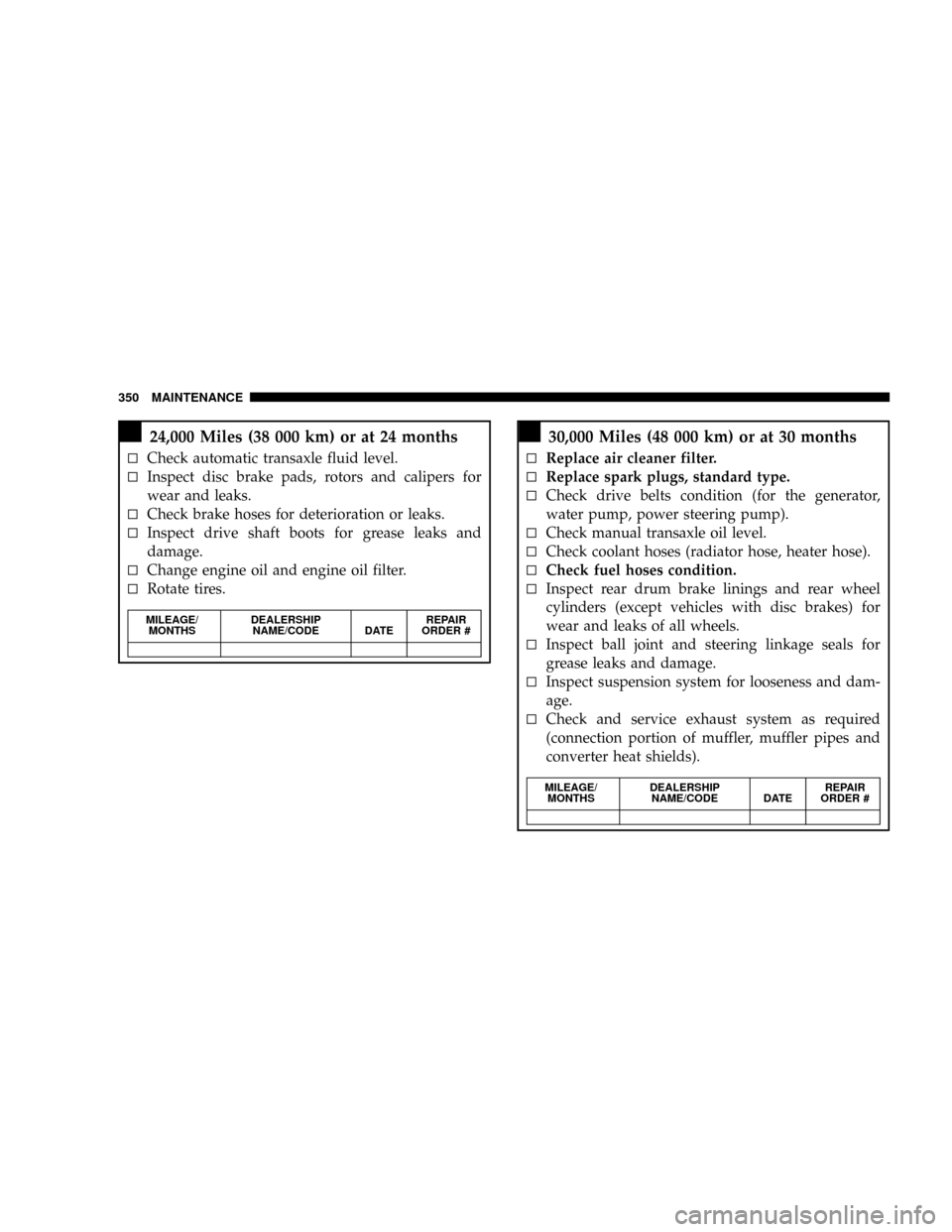
!24,000 Miles (38 000 km) or at 24 months
NCheck automatic transaxle fluid level.
NInspect disc brake pads, rotors and calipers for
wear and leaks.
NCheck brake hoses for deterioration or leaks.
NInspect drive shaft boots for grease leaks and
damage.
NChange engine oil and engine oil filter.
NRotate tires.
MILEAGE/
MONTHSDEALERSHIP
NAME/CODE DATEREPAIR
ORDER #
!30,000 Miles (48 000 km) or at 30 months
NReplace air cleaner filter.
NReplace spark plugs, standard type.
NCheck drive belts condition (for the generator,
water pump, power steering pump).
NCheck manual transaxle oil level.
NCheck coolant hoses (radiator hose, heater hose).
NCheck fuel hoses condition.
NInspect rear drum brake linings and rear wheel
cylinders (except vehicles with disc brakes) for
wear and leaks of all wheels.
NInspect ball joint and steering linkage seals for
grease leaks and damage.
NInspect suspension system for looseness and dam-
age.
NCheck and service exhaust system as required
(connection portion of muffler, muffler pipes and
converter heat shields).
MILEAGE/
MONTHSDEALERSHIP
NAME/CODE DATEREPAIR
ORDER #
350 MAINTENANCE