DODGE TOWN AND COUNTRY 2001 Service Manual
Manufacturer: DODGE, Model Year: 2001, Model line: TOWN AND COUNTRY, Model: DODGE TOWN AND COUNTRY 2001Pages: 2321, PDF Size: 68.09 MB
Page 1311 of 2321
(17) Remove the water pump for cover removal
clearance. (Refer to 7 - COOLING/ENGINE/WATER
PUMP - REMOVAL)
(18) Remove the bolt attaching the power steering
pump support strut to the front cover (Fig. 153).
(19) Remove the timing chain cover (Fig. 154).
INSTALLATION
(1) Be sure mating surfaces of chain case cover
and cylinder block are clean and free from burrs.
Crankshaft oil seal must be removed to insure cor-
rect oil pump engagement.
NOTE: DO NOT USE SEALER ON COVER GASKET
(2) Position new gasket on timing cover (Fig. 154).
Adhere new gasket to chain case cover, making sure
that the lower edge of the gasket is flush to 0.5 mm
(0.020 in.) passed the lower edge of the cover.
(3) Rotate crankshaft so that the oil pump drive
flats are in the vertical position.
(4) Position oil pump inner rotor so the mating
flats are in the same position as the crankshaft drive
flats (Fig. 154).
CAUTION: Make sure the oil pump is engaged on
the crankshaft correctly or severe damage may
result.
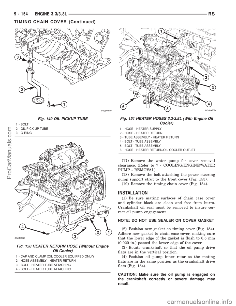
Fig. 149 OIL PICKUP TUBE
1 - BOLT
2 - OIL PICK-UP TUBE
3 - O-RING
Fig. 150 HEATER RETURN HOSE (Without Engine
Oil Cooler)
1 - CAP AND CLAMP (OIL COOLER EQUIPPED ONLY)
2 - HOSE ASSEMBLY - HEATER RETURN
3 - BOLT - HEATER TUBE ATTACHING
4 - BOLT - HEATER TUBE ATTACHING
Fig. 151 HEATER HOSES 3.3/3.8L (With Engine Oil
Cooler)
1 - HOSE - HEATER SUPPLY
2 - HOSE - HEATER RETURN
3 - TUBE ASSEMBLY - HEATER RETURN
4 - BOLT - TUBE ASSEMBLY
5 - BOLT - TUBE ASSEMBLY
6 - HOSE - HEATER RETURN/OIL COOLER OUTLET
9 - 154 ENGINE 3.3/3.8LRS
TIMING CHAIN COVER (Continued)
ProCarManuals.com
Page 1312 of 2321
(5) Install timing cover (Fig. 154).
(6) Install timing chain cover bolts. Tighten M8
bolts to 27 N´m (20 ft. lbs.) and M10 bolts to 54 N´m
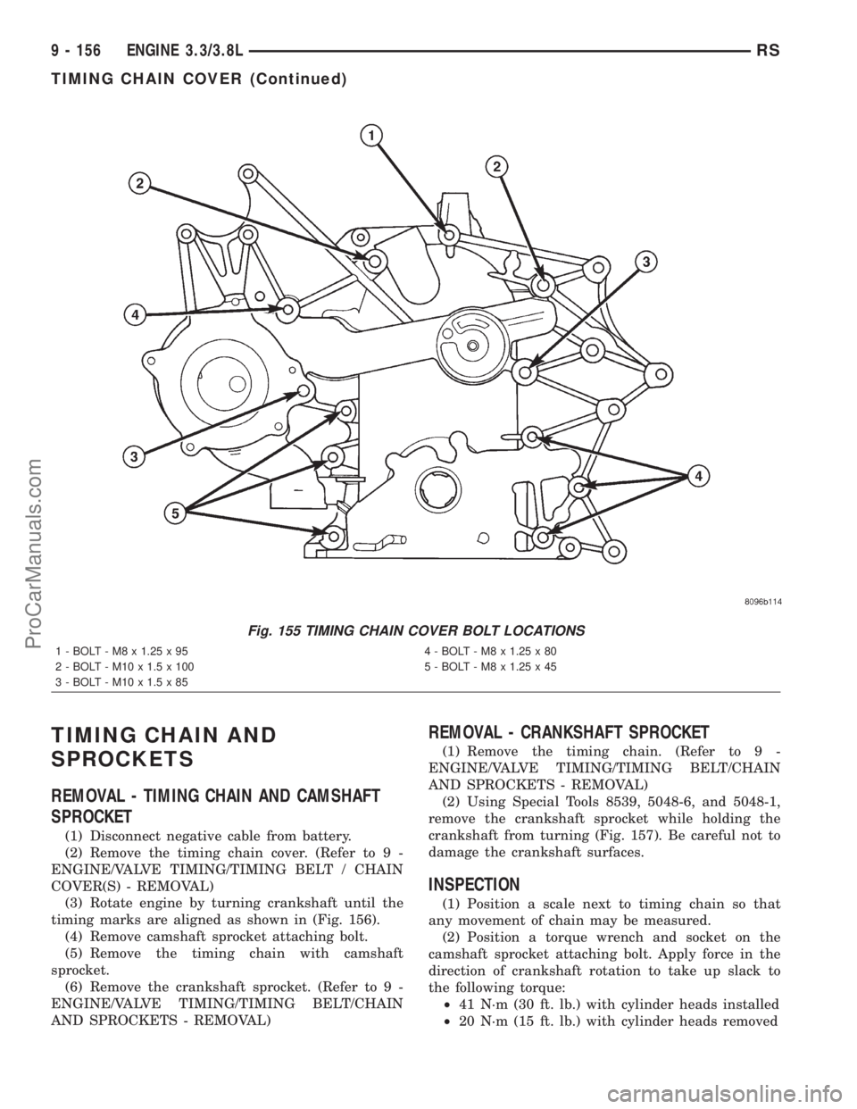
(40 ft. lbs.) (Fig. 155).
(7) Install crankshaft front oil seal. (Refer to 9 -
ENGINE/ENGINE BLOCK/CRANKSHAFT OIL
SEAL - FRONT - INSTALLATION)(8) Install water pump and pulley. (Refer to 7 -
COOLING/ENGINE/WATER PUMP - INSTALLA-
TION)
(9) Install crankshaft vibration damper. (Refer to 9
- ENGINE/ENGINE BLOCK/VIBRATION DAMPER -
INSTALLATION)
(10) Install engine mount bracket (Fig. 152) and
tighten M10 to 54 N´m (40 ft. lbs.), M8 bolt to 28
N´m (21 ft. lb. lbs.).
(11) Install idler pulley on engine mount bracket
(Fig. 152).
(12) Install right side engine mount. (Refer to 9 -
ENGINE/ENGINE MOUNTING/RIGHT MOUNT -
INSTALLATION)
(13) Install camshaft sensor. Refer to IGNITION
SYSTEM for procedure.
(14) Connect the heater return hose at rear of tim-
ing chain cover (Fig. 150) or at water pump inlet
tube (if engine oil cooler equipped) (Fig. 151).
(15) Connect the radiator lower hose.
(16) Install A/C compressor.
(17) Install accessory drive belt. (Refer to 7 -
COOLING/ACCESSORY DRIVE/DRIVE BELTS -
INSTALLATION)
(18) Install oil pump pick-up tube with new
O-ring. Tighten attaching bolt to 28 N´m (250 in.
lbs.).
(19) Install oil pan. (Refer to 9 - ENGINE/LUBRI-
CATION/OIL PAN - INSTALLATION)
(20) Install inner splash shield and right front
wheel.
(21) Fill crankcase with engine oil to proper level.
(22) Fill cooling system. (Refer to 7 - COOLING -
STANDARD PROCEDURE)
(23) Connect negative cable to battery.
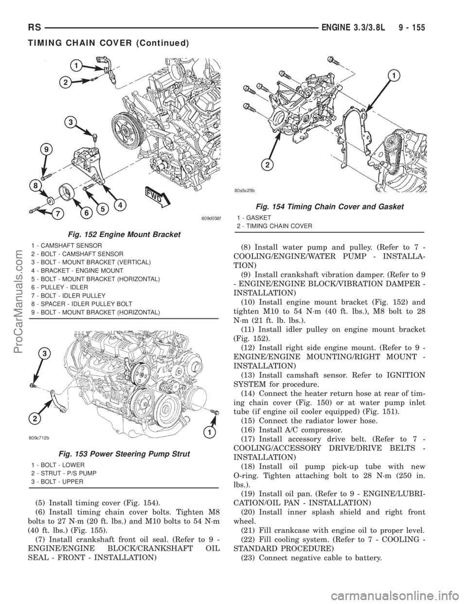
Fig. 152 Engine Mount Bracket
1 - CAMSHAFT SENSOR
2 - BOLT - CAMSHAFT SENSOR
3 - BOLT - MOUNT BRACKET (VERTICAL)
4 - BRACKET - ENGINE MOUNT
5 - BOLT - MOUNT BRACKET (HORIZONTAL)
6 - PULLEY - IDLER
7 - BOLT - IDLER PULLEY
8 - SPACER - IDLER PULLEY BOLT
9 - BOLT - MOUNT BRACKET (HORIZONTAL)
Fig. 153 Power Steering Pump Strut
1 - BOLT - LOWER
2 - STRUT - P/S PUMP
3 - BOLT - UPPER
Fig. 154 Timing Chain Cover and Gasket
1 - GASKET
2 - TIMING CHAIN COVER
RSENGINE 3.3/3.8L9 - 155
TIMING CHAIN COVER (Continued)
ProCarManuals.com
Page 1313 of 2321
TIMING CHAIN AND
SPROCKETS
REMOVAL - TIMING CHAIN AND CAMSHAFT
SPROCKET
(1) Disconnect negative cable from battery.
(2) Remove the timing chain cover. (Refer to 9 -
ENGINE/VALVE TIMING/TIMING BELT / CHAIN
COVER(S) - REMOVAL)
(3) Rotate engine by turning crankshaft until the
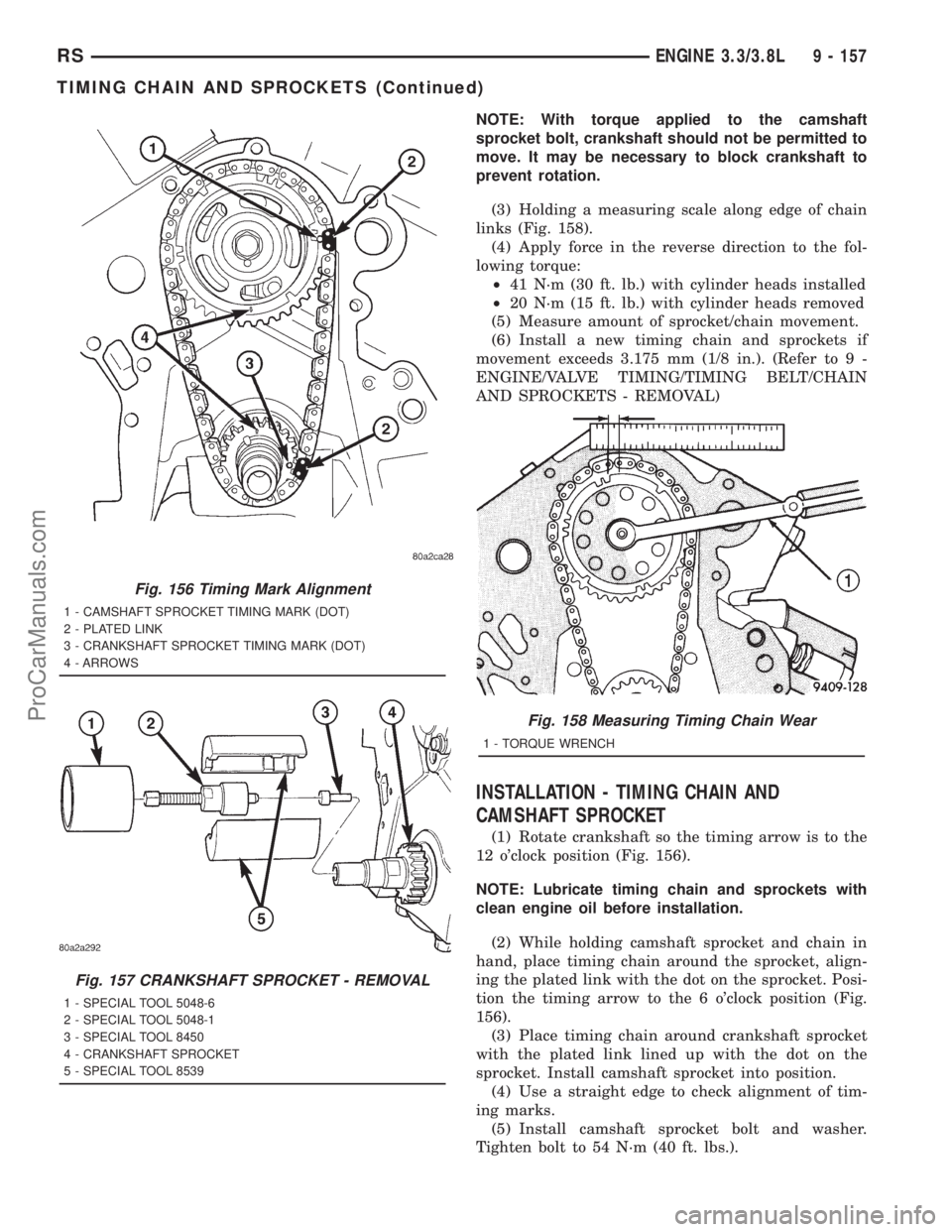
timing marks are aligned as shown in (Fig. 156).
(4) Remove camshaft sprocket attaching bolt.
(5) Remove the timing chain with camshaft
sprocket.
(6) Remove the crankshaft sprocket. (Refer to 9 -
ENGINE/VALVE TIMING/TIMING BELT/CHAIN
AND SPROCKETS - REMOVAL)
REMOVAL - CRANKSHAFT SPROCKET
(1) Remove the timing chain. (Refer to 9 -
ENGINE/VALVE TIMING/TIMING BELT/CHAIN
AND SPROCKETS - REMOVAL)
(2) Using Special Tools 8539, 5048-6, and 5048-1,
remove the crankshaft sprocket while holding the
crankshaft from turning (Fig. 157). Be careful not to
damage the crankshaft surfaces.
INSPECTION
(1) Position a scale next to timing chain so that
any movement of chain may be measured.
(2) Position a torque wrench and socket on the
camshaft sprocket attaching bolt. Apply force in the
direction of crankshaft rotation to take up slack to
the following torque:
²41 N´m (30 ft. lb.) with cylinder heads installed
²20 N´m (15 ft. lb.) with cylinder heads removed
Fig. 155 TIMING CHAIN COVER BOLT LOCATIONS
1 - BOLT - M8 x 1.25 x 95 4 - BOLT - M8 x 1.25 x 80
2 - BOLT - M10 x 1.5 x 100 5 - BOLT - M8 x 1.25 x 45
3 - BOLT - M10 x 1.5 x 85
9 - 156 ENGINE 3.3/3.8LRS
TIMING CHAIN COVER (Continued)
ProCarManuals.com
Page 1314 of 2321
NOTE: With torque applied to the camshaft
sprocket bolt, crankshaft should not be permitted to
move. It may be necessary to block crankshaft to
prevent rotation.
(3) Holding a measuring scale along edge of chain
links (Fig. 158).
(4) Apply force in the reverse direction to the fol-
lowing torque:
²41 N´m (30 ft. lb.) with cylinder heads installed
²20 N´m (15 ft. lb.) with cylinder heads removed
(5) Measure amount of sprocket/chain movement.
(6) Install a new timing chain and sprockets if
movement exceeds 3.175 mm (1/8 in.). (Refer to 9 -
ENGINE/VALVE TIMING/TIMING BELT/CHAIN
AND SPROCKETS - REMOVAL)
INSTALLATION - TIMING CHAIN AND
CAMSHAFT SPROCKET
(1) Rotate crankshaft so the timing arrow is to the
12 o'clock position (Fig. 156).
NOTE: Lubricate timing chain and sprockets with
clean engine oil before installation.
(2) While holding camshaft sprocket and chain in
hand, place timing chain around the sprocket, align-
ing the plated link with the dot on the sprocket. Posi-
tion the timing arrow to the 6 o'clock position (Fig.
156).
(3) Place timing chain around crankshaft sprocket
with the plated link lined up with the dot on the
sprocket. Install camshaft sprocket into position.
(4) Use a straight edge to check alignment of tim-
ing marks.
(5) Install camshaft sprocket bolt and washer.
Tighten bolt to 54 N´m (40 ft. lbs.).
Fig. 156 Timing Mark Alignment
1 - CAMSHAFT SPROCKET TIMING MARK (DOT)
2 - PLATED LINK
3 - CRANKSHAFT SPROCKET TIMING MARK (DOT)
4 - ARROWS
Fig. 157 CRANKSHAFT SPROCKET - REMOVAL
1 - SPECIAL TOOL 5048-6
2 - SPECIAL TOOL 5048-1
3 - SPECIAL TOOL 8450
4 - CRANKSHAFT SPROCKET
5 - SPECIAL TOOL 8539
Fig. 158 Measuring Timing Chain Wear
1 - TORQUE WRENCH
RSENGINE 3.3/3.8L9 - 157
TIMING CHAIN AND SPROCKETS (Continued)
ProCarManuals.com
Page 1315 of 2321
(6) Rotate crankshaft 2 revolutions and check tim-
ing mark alignment (Fig. 156). If timing marks do
not line up, remove camshaft sprocket and realign.
(7) Install the timing chain cover. (Refer to 9 -
ENGINE/VALVE TIMING/TIMING BELT / CHAIN
COVER(S) - INSTALLATION)
(8) Connect negative cable to battery.
INSTALLATION - CRANKSHAFT SPROCKET
(1) Position the sprocket on the crankshaft (timing
mark out) with the timing slot aligned with the tim-
ing pin.
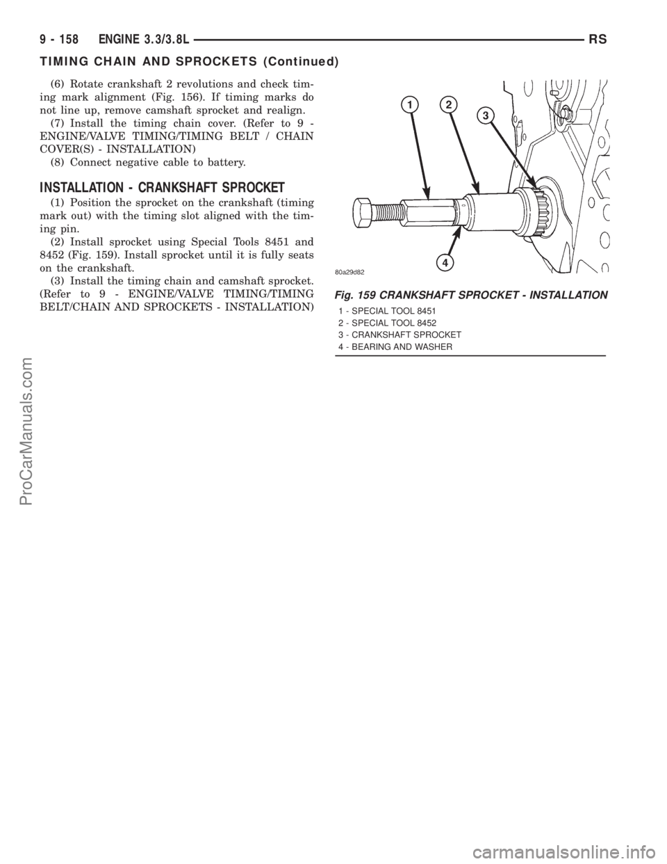
(2) Install sprocket using Special Tools 8451 and
8452 (Fig. 159). Install sprocket until it is fully seats
on the crankshaft.
(3) Install the timing chain and camshaft sprocket.
(Refer to 9 - ENGINE/VALVE TIMING/TIMING
BELT/CHAIN AND SPROCKETS - INSTALLATION)
Fig. 159 CRANKSHAFT SPROCKET - INSTALLATION
1 - SPECIAL TOOL 8451
2 - SPECIAL TOOL 8452
3 - CRANKSHAFT SPROCKET
4 - BEARING AND WASHER
9 - 158 ENGINE 3.3/3.8LRS
TIMING CHAIN AND SPROCKETS (Continued)
ProCarManuals.com
Page 1316 of 2321
ENGINE 2.5L TURBO DIESEL
TABLE OF CONTENTS
page page
ENGINE 2.5L TURBO DIESEL
DESCRIPTION............................2
REMOVAL...............................3
INSTALLATION............................6
SPECIFICATIONS.........................7
SPECIAL TOOLS.........................12
CYLINDER HEAD
STANDARD PROCEDURE..................18
VALVE SERVICE.......................18
MEASURING PISTON PROTRUSION........19
REMOVAL..............................20
CLEANING..............................21
INSPECTION............................22
INSTALLATION...........................22
CAMSHAFT(S)
DESCRIPTION...........................23
OPERATION.............................23
REMOVAL..............................23
INSTALLATION...........................24
CYLINDER HEAD COVER(S)
DESCRIPTION...........................24
REMOVAL..............................24
INSTALLATION...........................26
CAMSHAFT OIL SEAL(S)
REMOVAL..............................28
INSTALLATION...........................28
ROCKER ARMS
DESCRIPTION...........................28
OPERATION.............................28
REMOVAL..............................28
INSTALLATION...........................29
HYDRAULIC LIFTERS
DESCRIPTION...........................30
REMOVAL..............................30
INSPECTION............................31
INSTALLATION...........................31
ENGINE BLOCK
DESCRIPTION...........................31
CRANKSHAFT
DESCRIPTION...........................31
OPERATION.............................31
STANDARD PROCEDURE..................32
CHECKING CRANKSHAFT END PLAY.......32
REMOVAL..............................32
INSTALLATION...........................33
CYLINDER LINERS
DESCRIPTION...........................34
REMOVAL..............................34
INSPECTION............................34INSTALLATION...........................35
INTERNAL VACUUM PUMP
DESCRIPTION...........................36
REMOVAL..............................36
INSTALLATION...........................36
PISTON & CONNECTING ROD
DESCRIPTION...........................37
STANDARD PROCEDURE..................37
PISTON RING FITTING..................37
REMOVAL..............................38
INSPECTION............................38
INSTALLATION...........................40
CRANKSHAFT OIL SEAL - FRONT
REMOVAL..............................42
INSTALLATION...........................42
VIBRATION DAMPER
REMOVAL..............................43
INSTALLATION...........................44
ENGINE COVER - FRONT
DESCRIPTION...........................44
REMOVAL..............................44
INSTALLATION...........................45
CRANKSHAFT MAIN BEARINGS
REMOVAL..............................45
INSTALLATION...........................46
CRANKSHAFT OIL SEAL - REAR
REMOVAL..............................46
INSTALLATION...........................46
OIL PAN
REMOVAL..............................46
INSTALLATION...........................47
OIL PUMP
REMOVAL..............................47
INSTALLATION...........................48
OIL PRESSURE SENSOR/SWITCH
DESCRIPTION...........................49
REMOVAL..............................49
INSTALLATION...........................50
OIL TEMPERATURE SENSOR
DESCRIPTION...........................50
REMOVAL..............................50
INSTALLATION...........................50
OIL PRESSURE RELIEF VALVE
DESCRIPTION...........................50
REMOVAL..............................51
INSTALLATION...........................51
OIL COOLER & LINES
REMOVAL..............................51
INSTALLATION...........................52
RGENGINE 2.5L TURBO DIESEL9a-1
ProCarManuals.com
Page 1317 of 2321
OIL FILTER
DESCRIPTION...........................52
REMOVAL..............................53
INSTALLATION...........................53
OIL JET
DESCRIPTION...........................53
REMOVAL..............................53
INSTALLATION...........................53
INTAKE MANIFOLD
DESCRIPTION...........................54
REMOVAL..............................54
INSTALLATION...........................54
VALVE TIMING
STANDARD PROCEDURE..................54
LOCKING ENGINE 90É AFTER TDC.........54
BALANCE SHAFT
DESCRIPTION...........................55OPERATION.............................56
REMOVAL..............................56
INSTALLATION...........................57
TIMING BELT / CHAIN COVER(S)
REMOVAL..............................57
INSTALLATION...........................58
TIMING BELT IDLER PULLEY
REMOVAL..............................59
INSTALLATION...........................60
TIMING BELT/CHAIN TENSIONER
REMOVAL..............................60
INSTALLATION...........................60
ADJUSTMENTS..........................61
TIMING BELT/CHAIN AND SPROCKETS
REMOVAL..............................62
INSTALLATION...........................63
ENGINE 2.5L TURBO DIESEL
DESCRIPTION - 2.5L COMMON RAIL DIESEL
ENGINE
This 2.5 Liter (2500cc) four-cylinder ªcommon railº
direct injection engine is an in-line overhead valve
diesel engine. This engine utilizes a cast iron cylin-
der block and an aluminum cylinder head. The
engine is turbocharged and intercooled. The engine
also has four valves per cylinder and dual overhead
camshafts (Fig. 1).
DESCRIPTION SPECIFICATION
Displacement 2.5L (2499 cc)
Bore 92.00
Stroke 94.00
Compression Ratio 17.5:1
Vacuum at Idle 685.8 mm/Hg (27.0
In/Hg)
Belt Tension Automatic Belt Tensioner
Thermostat Opening 80ÉC 2ÉC
Generator Rating Denso 12V-95A
DESCRIPTION SPECIFICATION
Cooling System Capacity 13.8 Liters W/O Auxiliary
Heater
16.6 Liters With Auxiliary
Heater
Engine Oil Capacity 5.22L W/Filter Change
Timing System Belt Driven Camshafts In
Cylinder Head Cover
Air Intake Dry Filter
Fuel Feed Vane Pump Incorporated
In Injection Pump
Fuel System Direct Fuel Injection
Combustion Cycle 4 Stroke
Cooling System Water Cooling
Injection Pump Rotary Pump and
Electronically Managed
Lubrication Pressure Lubricated By
Rotary Pump
Engine Rotation Clockwise Viewed From
Front Cover
9a - 2 ENGINE 2.5L TURBO DIESELRG
ProCarManuals.com
Page 1318 of 2321
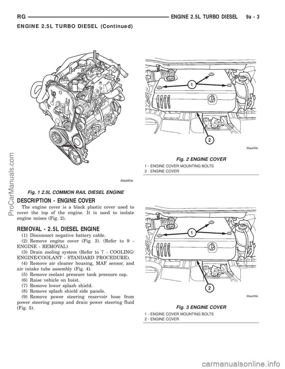
DESCRIPTION - ENGINE COVER
The engine cover is a black plastic cover used to
cover the top of the engine. It is used to isolate
engine noises (Fig. 2).
REMOVAL - 2.5L DIESEL ENGINE
(1) Disconnect negative battery cable.
(2) Remove engine cover (Fig. 3). (Refer to 9 -
ENGINE - REMOVAL)
(3) Drain cooling system (Refer to 7 - COOLING/
ENGINE/COOLANT - STANDARD PROCEDURE).
(4) Remove air cleaner housing, MAF sensor, and
air intake tube assembly (Fig. 4).
(5) Remove coolant pressure tank pressure cap.
(6) Raise vehicle on hoist.
(7) Remove lower splash shield.
(8) Remove splash shield side panels.
(9) Remove power steering reservoir hose from
power steering pump and drain power steering fluid
(Fig. 5).
Fig. 1 2.5L COMMON RAIL DIESEL ENGINE
Fig. 2 ENGINE COVER
1 - ENGINE COVER MOUNTING BOLTS
2 - ENGINE COVER
Fig. 3 ENGINE COVER
1 - ENGINE COVER MOUNTING BOLTS
2 - ENGINE COVER
RGENGINE 2.5L TURBO DIESEL9a-3
ENGINE 2.5L TURBO DIESEL (Continued)
ProCarManuals.com
Page 1319 of 2321
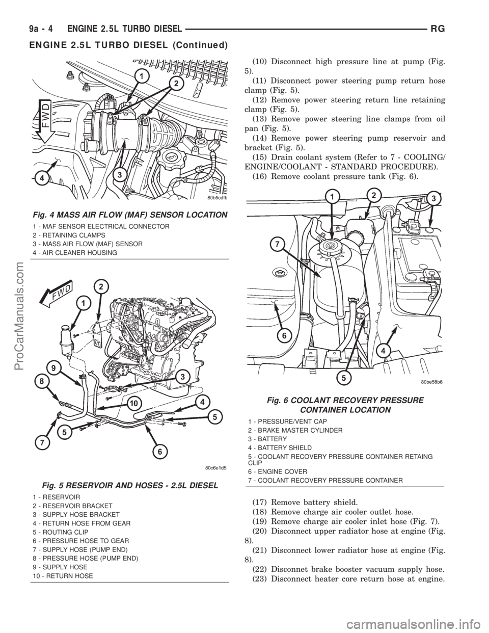
(10) Disconnect high pressure line at pump (Fig.
5).
(11) Disconnect power steering pump return hose
clamp (Fig. 5).
(12) Remove power steering return line retaining
clamp (Fig. 5).
(13) Remove power steering line clamps from oil
pan (Fig. 5).
(14) Remove power steering pump reservoir and
bracket (Fig. 5).
(15) Drain coolant system (Refer to 7 - COOLING/
ENGINE/COOLANT - STANDARD PROCEDURE).
(16) Remove coolant pressure tank (Fig. 6).
(17) Remove battery shield.
(18) Remove charge air cooler outlet hose.
(19) Remove charge air cooler inlet hose (Fig. 7).
(20) Disconnect upper radiator hose at engine (Fig.
8).
(21) Disconnect lower radiator hose at engine (Fig.
8).
(22) Disconnet brake booster vacuum supply hose.
(23) Disconnect heater core return hose at engine.
Fig. 4 MASS AIR FLOW (MAF) SENSOR LOCATION
1 - MAF SENSOR ELECTRICAL CONNECTOR
2 - RETAINING CLAMPS
3 - MASS AIR FLOW (MAF) SENSOR
4 - AIR CLEANER HOUSING
Fig. 5 RESERVOIR AND HOSES - 2.5L DIESEL
1 - RESERVOIR
2 - RESERVOIR BRACKET
3 - SUPPLY HOSE BRACKET
4 - RETURN HOSE FROM GEAR
5 - ROUTING CLIP
6 - PRESSURE HOSE TO GEAR
7 - SUPPLY HOSE (PUMP END)
8 - PRESSURE HOSE (PUMP END)
9 - SUPPLY HOSE
10 - RETURN HOSE
Fig. 6 COOLANT RECOVERY PRESSURE
CONTAINER LOCATION
1 - PRESSURE/VENT CAP
2 - BRAKE MASTER CYLINDER
3 - BATTERY
4 - BATTERY SHIELD
5 - COOLANT RECOVERY PRESSURE CONTAINER RETAING
CLIP
6 - ENGINE COVER
7 - COOLANT RECOVERY PRESSURE CONTAINER
9a - 4 ENGINE 2.5L TURBO DIESELRG
ENGINE 2.5L TURBO DIESEL (Continued)
ProCarManuals.com
Page 1320 of 2321
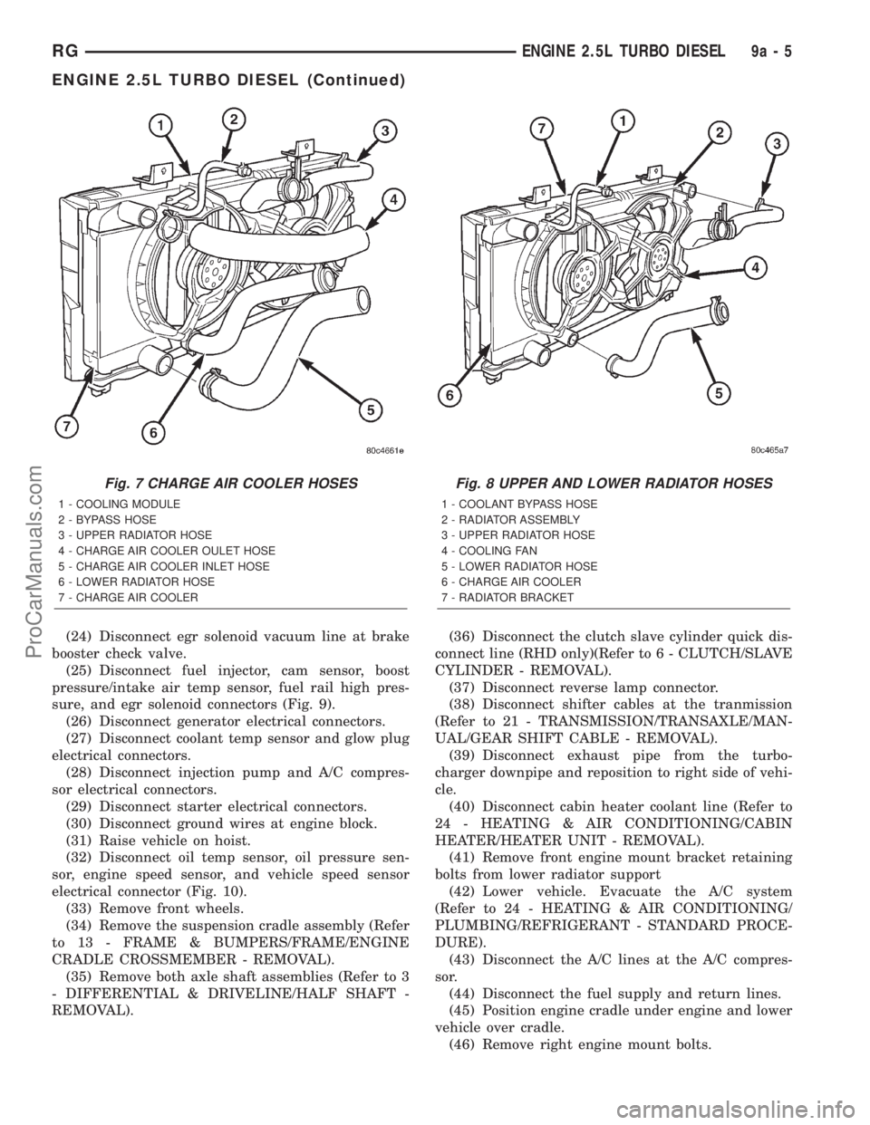
(24) Disconnect egr solenoid vacuum line at brake
booster check valve.
(25) Disconnect fuel injector, cam sensor, boost
pressure/intake air temp sensor, fuel rail high pres-
sure, and egr solenoid connectors (Fig. 9).
(26) Disconnect generator electrical connectors.
(27) Disconnect coolant temp sensor and glow plug
electrical connectors.
(28) Disconnect injection pump and A/C compres-
sor electrical connectors.
(29) Disconnect starter electrical connectors.
(30) Disconnect ground wires at engine block.
(31) Raise vehicle on hoist.
(32) Disconnect oil temp sensor, oil pressure sen-
sor, engine speed sensor, and vehicle speed sensor
electrical connector (Fig. 10).
(33) Remove front wheels.
(34) Remove the suspension cradle assembly (Refer
to 13 - FRAME & BUMPERS/FRAME/ENGINE
CRADLE CROSSMEMBER - REMOVAL).
(35) Remove both axle shaft assemblies (Refer to 3
- DIFFERENTIAL & DRIVELINE/HALF SHAFT -
REMOVAL).(36) Disconnect the clutch slave cylinder quick dis-
connect line (RHD only)(Refer to 6 - CLUTCH/SLAVE
CYLINDER - REMOVAL).
(37) Disconnect reverse lamp connector.
(38) Disconnect shifter cables at the tranmission
(Refer to 21 - TRANSMISSION/TRANSAXLE/MAN-
UAL/GEAR SHIFT CABLE - REMOVAL).
(39) Disconnect exhaust pipe from the turbo-
charger downpipe and reposition to right side of vehi-
cle.
(40) Disconnect cabin heater coolant line (Refer to
24 - HEATING & AIR CONDITIONING/CABIN
HEATER/HEATER UNIT - REMOVAL).
(41) Remove front engine mount bracket retaining
bolts from lower radiator support
(42) Lower vehicle. Evacuate the A/C system
(Refer to 24 - HEATING & AIR CONDITIONING/
PLUMBING/REFRIGERANT - STANDARD PROCE-
DURE).
(43) Disconnect the A/C lines at the A/C compres-
sor.
(44) Disconnect the fuel supply and return lines.
(45) Position engine cradle under engine and lower
vehicle over cradle.
(46) Remove right engine mount bolts.
Fig. 7 CHARGE AIR COOLER HOSES
1 - COOLING MODULE
2 - BYPASS HOSE
3 - UPPER RADIATOR HOSE
4 - CHARGE AIR COOLER OULET HOSE
5 - CHARGE AIR COOLER INLET HOSE
6 - LOWER RADIATOR HOSE
7 - CHARGE AIR COOLER
Fig. 8 UPPER AND LOWER RADIATOR HOSES
1 - COOLANT BYPASS HOSE
2 - RADIATOR ASSEMBLY
3 - UPPER RADIATOR HOSE
4 - COOLING FAN
5 - LOWER RADIATOR HOSE
6 - CHARGE AIR COOLER
7 - RADIATOR BRACKET
RGENGINE 2.5L TURBO DIESEL9a-5
ENGINE 2.5L TURBO DIESEL (Continued)
ProCarManuals.com