DODGE TOWN AND COUNTRY 2001 Service Manual
TOWN AND COUNTRY 2001
DODGE
DODGE
https://www.carmanualsonline.info/img/12/56921/w960_56921-0.png
DODGE TOWN AND COUNTRY 2001 Service Manual
Trending: tires, mirror, airbag off, immobilizer, oil change, hood release, key fob battery
Page 1921 of 2321
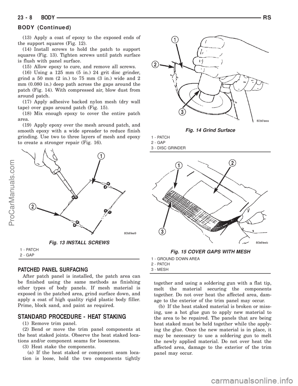
(13) Apply a coat of epoxy to the exposed ends of
the support squares (Fig. 12).
(14) Install screws to hold the patch to support
squares (Fig. 13). Tighten screws until patch surface
is flush with panel surface.
(15) Allow epoxy to cure, and remove all screws.
(16) Using a 125 mm (5 in.) 24 grit disc grinder,
grind a 50 mm (2 in.) to 75 mm (3 in.) wide and 2
mm (0.080 in.) deep path across the gaps around the
patch (Fig. 14). With compressed air, blow dust from
around patch.
(17) Apply adhesive backed nylon mesh (dry wall
tape) over gaps around patch (Fig. 15).
(18) Mix enough epoxy to cover the entire patch
area.
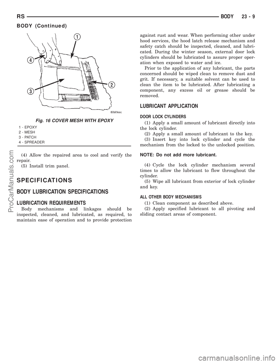
(19) Apply epoxy over the mesh around patch, and
smooth epoxy with a wide spreader to reduce finish
grinding. Use two to three layers of mesh and epoxy
to create a stronger repair (Fig. 16).
PATCHED PANEL SURFACING
After patch panel is installed, the patch area can
be finished using the same methods as finishing
other types of body panels. If mesh material is
exposed in the patched area, grind surface down, and
apply a coat of high quality rigid plastic body filler.
Prime, block sand, and paint as required.
STANDARD PROCEDURE - HEAT STAKING
(1) Remove trim panel.
(2) Bend or move the trim panel components at
the heat staked joints. Observe the heat staked loca-
tions and/or component seams for looseness.
(3) Heat stake the components.
(a) If the heat staked or component seam loca-
tion is loose, hold the two components tightlytogether and using a soldering gun with a flat tip,
melt the material securing the components
together. Do not over heat the affected area, dam-
age to the exterior of the trim panel may occur.
(b) If the heat staked material is broken or miss-
ing, use a hot glue gun to apply new material to
the area to be repaired. The panels that are being
heat staked must be held together while the apply-
ing the glue. Once the new material is in place, it
may be necessary to use a soldering gun to melt
the newly applied material. Do not over heat the
affected area, damage to the exterior of the trim
panel may occur.
Fig. 13 INSTALL SCREWS
1 - PATCH
2 - GAP
Fig. 14 Grind Surface
1 - PATCH
2 - GAP
3 - DISC GRINDER
Fig. 15 COVER GAPS WITH MESH
1 - GROUND DOWN AREA
2 - PATCH
3 - MESH
23 - 8 BODYRS
BODY (Continued)
ProCarManuals.com
Page 1922 of 2321
(4) Allow the repaired area to cool and verify the
repair.
(5) Install trim panel.
SPECIFICATIONS
BODY LUBRICATION SPECIFICATIONS
LUBRICATION REQUIREMENTS
Body mechanisms and linkages should be
inspected, cleaned, and lubricated, as required, to
maintain ease of operation and to provide protectionagainst rust and wear. When performing other under
hood services, the hood latch release mechanism and
safety catch should be inspected, cleaned, and lubri-
cated. During the winter season, external door lock
cylinders should be lubricated to assure proper oper-
ation when exposed to water and ice.
Prior to the application of any lubricant, the parts
concerned should be wiped clean to remove dust and
grit. If necessary, a suitable solvent can be used to
clean the item to be lubricated. After lubricating a
component, any excess oil or grease should be
removed.
LUBRICANT APPLICATION
DOOR LOCK CYLINDERS
(1) Apply a small amount of lubricant directly into
the lock cylinder.
(2) Apply a small amount of lubricant to the key.
(3) Insert key into lock cylinder and cycle the
mechanism from the locked to the unlocked position.
NOTE: Do not add more lubricant.
(4) Cycle the lock cylinder mechanism several
times to allow the lubricant to flow throughout the
cylinder.
(5) Wipe all lubricant from exterior of lock cylinder
and key.
ALL OTHER BODY MECHANISMS
(1) Clean component as described above.
(2) Apply specified lubricant to all pivoting and
sliding contact areas of component.Fig. 16 COVER MESH WITH EPOXY
1 - EPOXY
2 - MESH
3 - PATCH
4 - SPREADER
RSBODY23-9
BODY (Continued)
ProCarManuals.com
Page 1923 of 2321
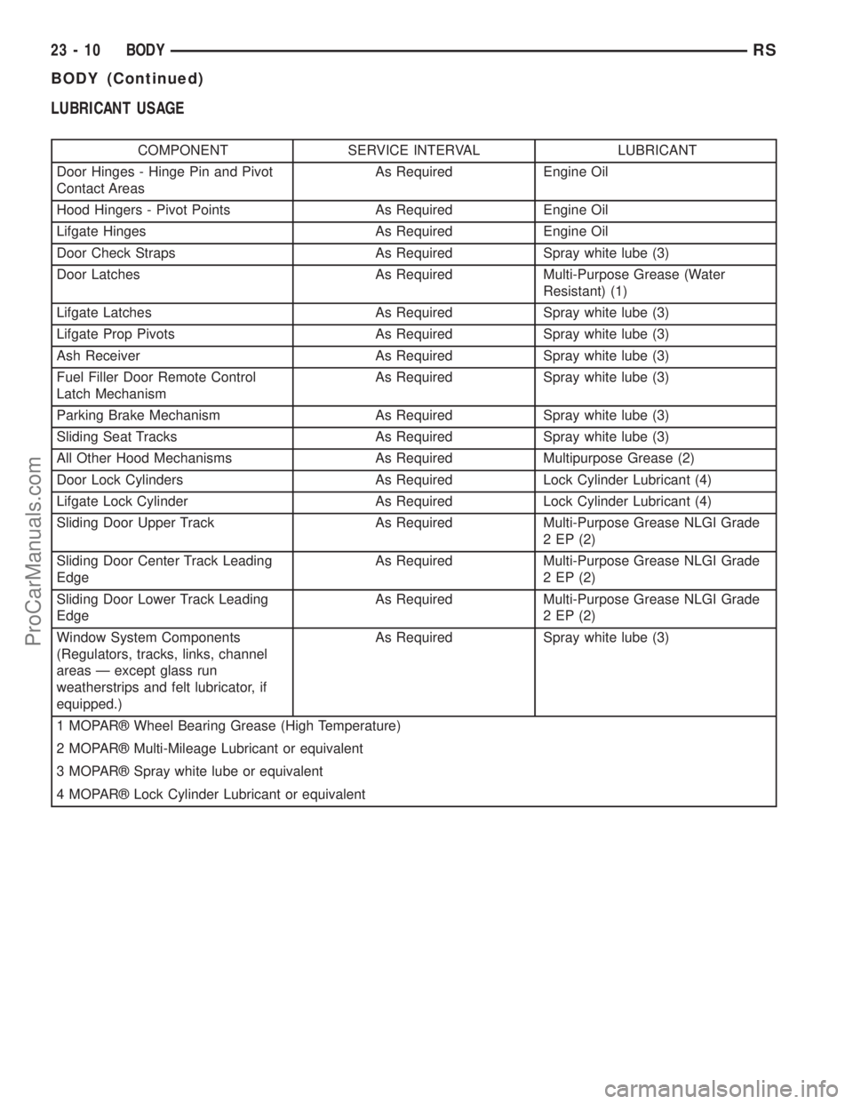
LUBRICANT USAGE
COMPONENT SERVICE INTERVAL LUBRICANT
Door Hinges - Hinge Pin and Pivot
Contact AreasAs Required Engine Oil
Hood Hingers - Pivot Points As Required Engine Oil
Lifgate Hinges As Required Engine Oil
Door Check Straps As Required Spray white lube (3)
Door Latches As Required Multi-Purpose Grease (Water
Resistant) (1)
Lifgate Latches As Required Spray white lube (3)
Lifgate Prop Pivots As Required Spray white lube (3)
Ash Receiver As Required Spray white lube (3)
Fuel Filler Door Remote Control
Latch MechanismAs Required Spray white lube (3)
Parking Brake Mechanism As Required Spray white lube (3)
Sliding Seat Tracks As Required Spray white lube (3)
All Other Hood Mechanisms As Required Multipurpose Grease (2)
Door Lock Cylinders As Required Lock Cylinder Lubricant (4)
Lifgate Lock Cylinder As Required Lock Cylinder Lubricant (4)
Sliding Door Upper Track As Required Multi-Purpose Grease NLGI Grade
2 EP (2)
Sliding Door Center Track Leading
EdgeAs Required Multi-Purpose Grease NLGI Grade
2 EP (2)
Sliding Door Lower Track Leading
EdgeAs Required Multi-Purpose Grease NLGI Grade
2 EP (2)
Window System Components
(Regulators, tracks, links, channel
areas Ð except glass run
weatherstrips and felt lubricator, if
equipped.)As Required Spray white lube (3)
1 MOPARž Wheel Bearing Grease (High Temperature)
2 MOPARž Multi-Mileage Lubricant or equivalent
3 MOPARž Spray white lube or equivalent
4 MOPARž Lock Cylinder Lubricant or equivalent
23 - 10 BODYRS
BODY (Continued)
ProCarManuals.com
Page 1924 of 2321
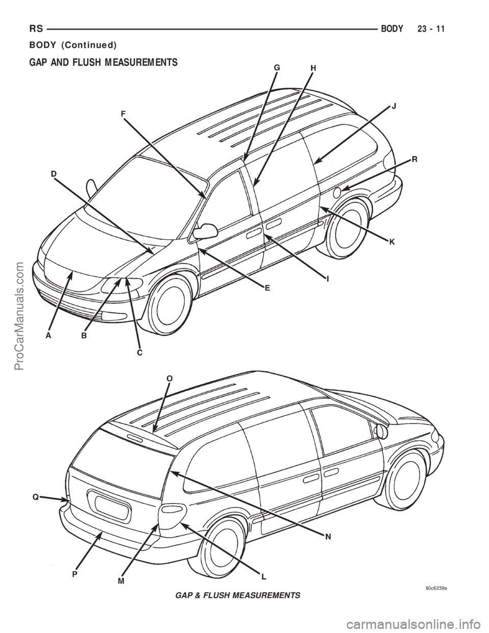
GAP AND FLUSH MEASUREMENTS
GAP & FLUSH MEASUREMENTS
RSBODY23-11
BODY (Continued)
ProCarManuals.com
Page 1925 of 2321
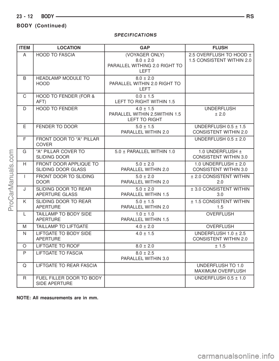
SPECIFICATIONS
ITEM LOCATION GAP FLUSH
A HOOD TO FASCIA (VOYAGER ONLY)
8.0 2.0
PARALLEL WITHING 2.0 RIGHT TO
LEFT2.5 OVERFLUSH TO HOOD
1.5 CONSISTENT WITHIN 2.0
B HEADLAMP MODULE TO
HOOD8.0 2.0
PARALLEL WITHIN 2.0 RIGHT TO
LEFT
C HOOD TO FENDER (FOR &
AFT)0.0 1.5
LEFT TO RIGHT WITHIN 1.5
D HOOD TO FENDER 4.0 1.5
PARALLEL WITHIN 2.5WITHIN 1.5
LEFT TO RIGHTUNDERFLUSH
2.0
E FENDER TO DOOR 5.0 1.5
PARALLEL WITHIN 2.0UNDERFLUSH 0.5 1.5
CONSISTENT WITHIN 2.0
F FRONT DOOR TO9A9PILLAR
COVERUNDERFLUSH 0.5 2.0
G9A9PILLAR COVER TO
SLIDING DOOR5.0 PARALLEL WITHIN 1.0 1.0 UNDERFLUSH
CONSISTENT WITHIN 3.0
H FRONT DOOR APPLIQUE TO
SLIDING DOOR GLASS5.0 2.0
PARALLEL WITHIN 2.01.0 UNDERFLUSH 2.0
CONSISTENT WITHIN 3.0
I FRONT DOOR TO SLIDING
DOOR5.0 2.0
PARALLEL WITHIN 2.0 2.0 CONSISTENT WITHIN
2.0
J SLIDING DOOR TO REAR
APERTURE GLASS5.0 2.0
PARALLEL WITHIN 1.5 3.0 CONSISTENT WITHIN
3.0
K SLIDING DOOR TO REAR
APERTURE5.0 1.5
PARALLEL WITHIN 2.0 1.5 CONSISTENT WITHIN
1.5
L TAILLAMP TO BODY SIDE
APERTURE1.0 1.0
PARALLEL WITHIN 1.5OVERFLUSH
M TAILLAMP TO LIFTGATE 4.0 2.0 OVERFLUSH
N LIFTGATE TO BODY SIDE
APERTURE4.0 1.5 UNDERFLUSH 1.0 2.5
CONSISTENT WITHIN 2.0
O LIFTGATE TO ROOF 8.0 2.0 1.5
P LIFTGATE TO FASCIA 8.0 2.5
PARALLEL WITHIN 3.0
Q LIFTGATE TO REAR FASCIA UNDERFLUSH TO 1.0
MAXIMUM OVERFLUSH
R FUEL FILLER DOOR TO BODY
SIDE APERTUREUNDERFLUSH 0.5 1.0
NOTE: All measurements are in mm.
23 - 12 BODYRS
BODY (Continued)
ProCarManuals.com
Page 1926 of 2321
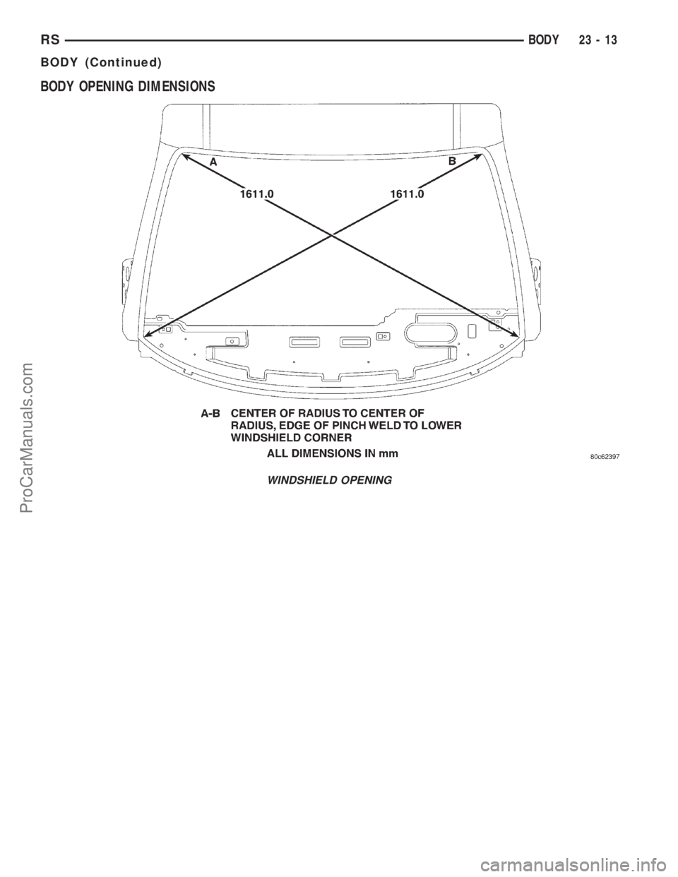
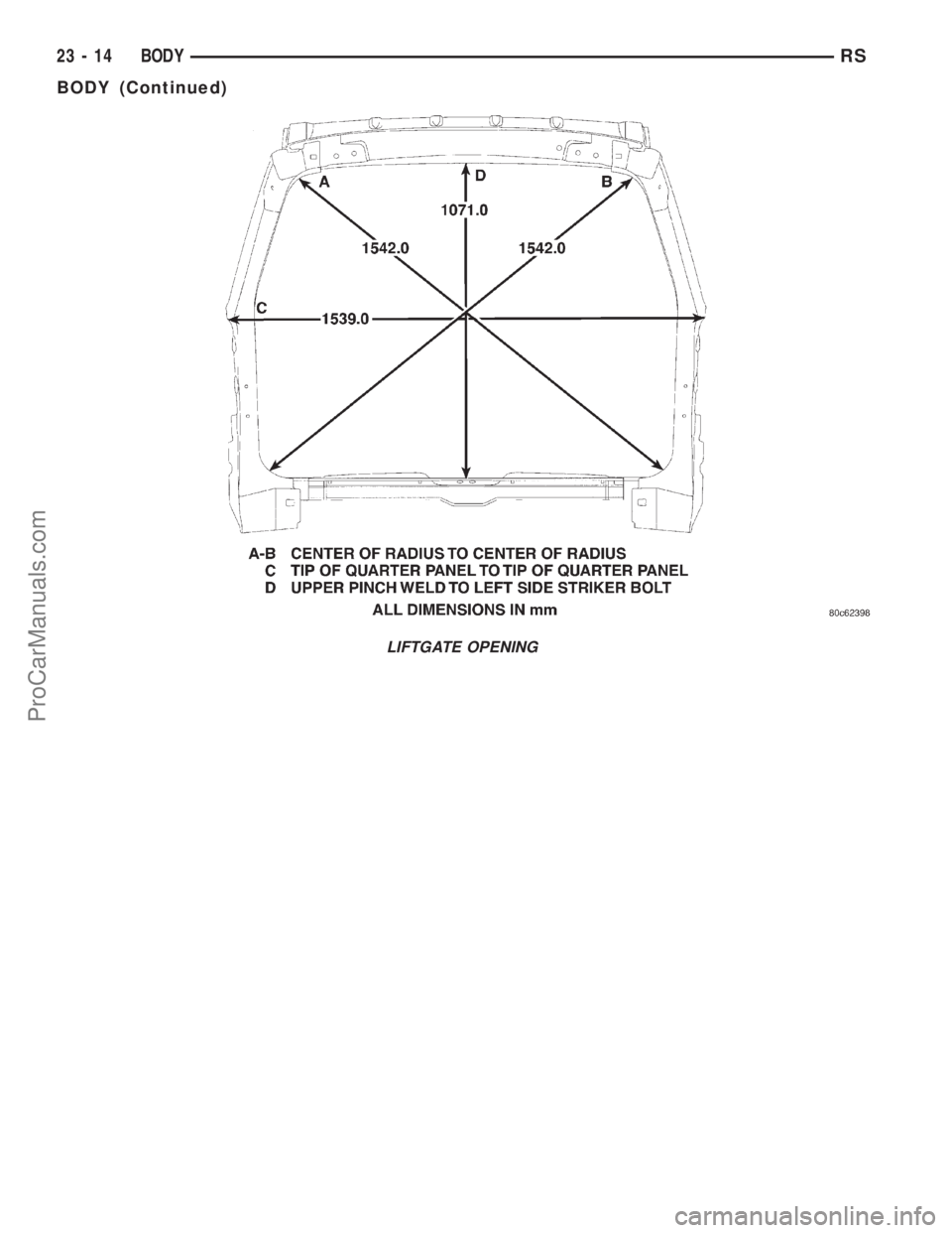
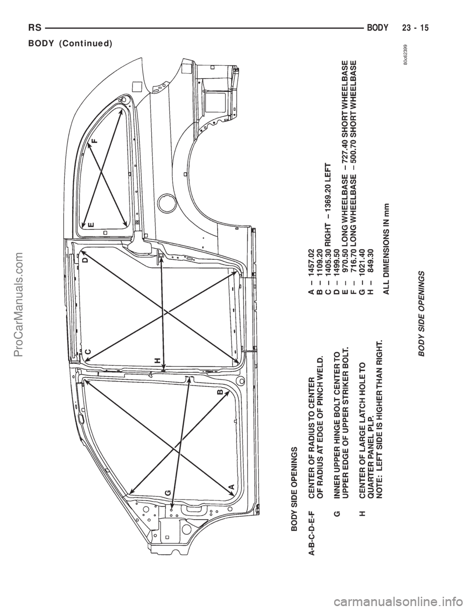
BODY OPENING DIMENSIONS
WINDSHIELD OPENING
RSBODY23-13
BODY (Continued)
ProCarManuals.com
Page 1927 of 2321
LIFTGATE OPENING
23 - 14 BODYRS
BODY (Continued)
ProCarManuals.com
Page 1928 of 2321
BODY SIDE OPENINGS
RSBODY23-15
BODY (Continued)
ProCarManuals.com
Page 1929 of 2321
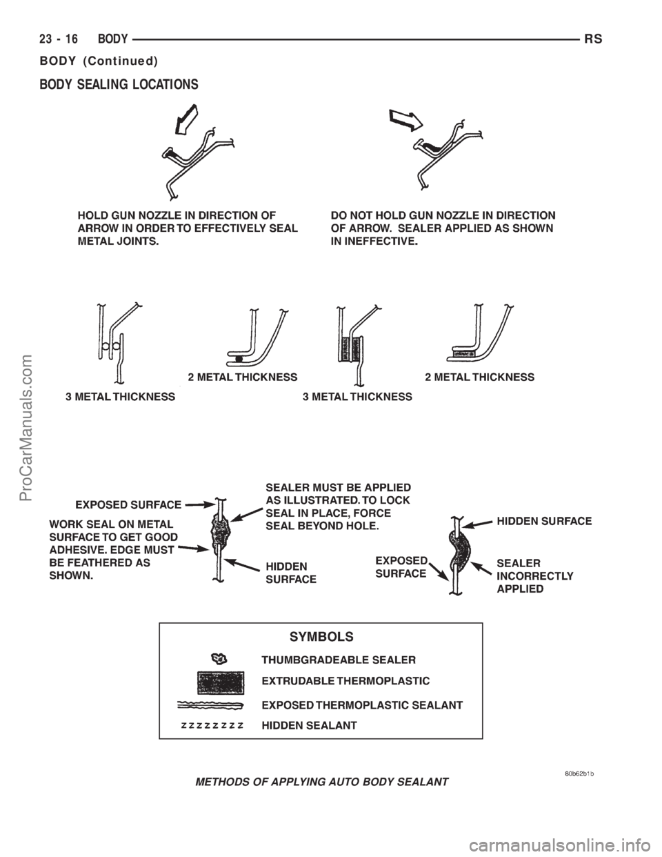
BODY SEALING LOCATIONS
METHODS OF APPLYING AUTO BODY SEALANT
23 - 16 BODYRS
BODY (Continued)
ProCarManuals.com
Page 1930 of 2321
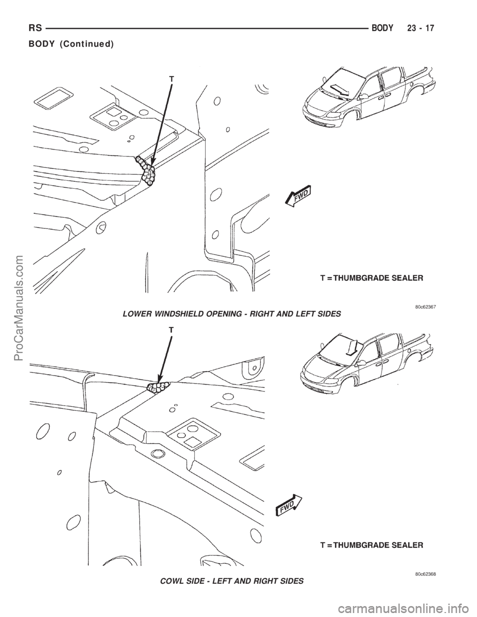
LOWER WINDSHIELD OPENING - RIGHT AND LEFT SIDES
COWL SIDE - LEFT AND RIGHT SIDES
RSBODY23-17
BODY (Continued)
ProCarManuals.com
Trending: steering, seat memory, jacking points, windshield wipers, parking brake, height adjustment, hood open


