check transmission fluid DODGE TRUCK 1993 Service Owner's Guide
[x] Cancel search | Manufacturer: DODGE, Model Year: 1993, Model line: TRUCK, Model: DODGE TRUCK 1993Pages: 1502, PDF Size: 80.97 MB
Page 1103 of 1502
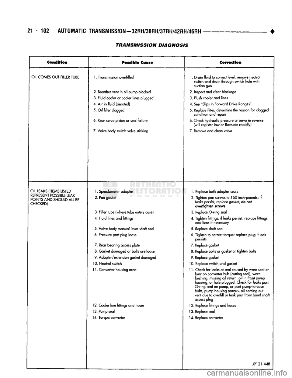
21-102
AUTOMATIC
TRANSMISSION—32RH/36RH/37RH/42RH/46RH
TRANSMISSION
DIAGNOSIS
•
Condition
Possible
Cause Correction
OIL
COMES
OUT
FILLER
TUBE
1.
Transmission
overfilled
1.
Drain
fluid
to
correct
level;
remove
neutral
switch
and drain
through
switch
hole
with
suction
gun
2.
Breather
vent
in
oil
pump
blocked
2.
Inspect
and
clear
blockage
3,
Fly id
cooler
or cooler
lines
plugged
3.
Flush
cooler and lines
4. Air in
fluid
(aerated)
4.
See
"Slips
In
Forward
Drive
Ranges"
5.
Oil
filter
clogged
5.
Replace
filter;
determine
the reason for clogged
condition and
repair
6.
tear
servo
piston
or
seal
failure
6.
Check hydraulic pressure at servo
in
reverse
(will
register
low or
fluctuate
rapidly)
7.
Valve body
switch
valve
sticking
7.
Remove
and
clean
valve
OIL
LEAKS
(ITEMS
LISTED
REPRESENT
POSSIBLE
LEAK
POINTS
AND
SHOULD
ALL
BE
CHECKED)
1.
Speedometer
adapter
2.
Pan
gasket
3.
Filler
tube
(where
tube
enters
case)
4.
Fluid
lines
and
fittings
5.
Valve body
manual
lever
shaft
seal
6.
Pressure
port
plug
loose 7. Rear
bearing
access
plate
8. Gasket damaged or
bolts
are loose
9.
Adapter/extension
gasket damaged
10.
Neutral
switch
11.
Converter
housing area
12. Cooler
line
fittings and hoses
13. Pump seal
14. Torque converter
1.
Replace both adapter seals
2. Tighten pan screws to 150 inch-pounds; if
leaks
persist,
replace
gasket;
do not
overtighten screws
3. Replace O-ring seal
4. Tighten fittings; if leaks persist, replace fittings and lines if necessary
5. Replace shaft seal
6. Tighten to correct torque; replace plug if leak
persists
7. Replace gasket
8. Replace bolts or gasket or tighten bolts
9. Replace gasket
10. Replace switch and gasket
11. Check for leaks at seal caused by worn seal or burr on converter hub (cutting seal), worn
bushing,
missing
oil
return,
oil in
front
pump
housing,
or hole plugged. Check for leaks past
O-ring seal on pump, or past pump-to-case
bolts;
pump housing porous, oil coming out
vent due to
overfill
or leak past
front
band shaft
access
plug
12. Replace fittings and hoses
13. Replace seal 14. Replace converter
J9121-448
Page 1104 of 1502
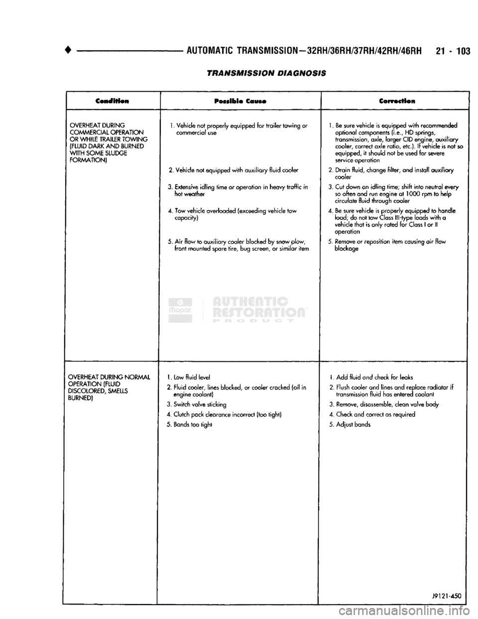
•
AUTOMATIC
TRANSMISSION—32RH/36RH/37RH/42RH/46RH
21-103
TRANSMISSION DIAGNOSIS
Condition
Possible
Couso
Correction
OVERHEAT
DURING
COMMERCIAL
OPERATION
OR
WHILE
TRAILER
TOWING
(FLUID
DARK
AND
BURNED
WITH
SOME
SLUDGE
FORMATION)
1.
Vehicle not properly equipped for
trailer
towing or
commercial use
2. Vehicle not equipped
with
auxiliary fluid cooler
3.
Extensive idling
time
or operation in heavy
traffic
in hot weather
4. Tow vehicle overloaded (exceeding vehicle tow capacity)
5. Air flow to auxiliary cooler blocked by snow plow,
front
mounted spare
tire,
bug screen, or similar
item
1.
Be sure vehicle is equipped
with
recommended
optional components
(i.e.,
HD
springs,
transmission,
axle, larger CID engine, auxiliary cooler, correct axle ratio, etc.). If vehicle is not so
equipped, it should not be used for severe
service operation
2. Drain fluid, change
filter,
and install auxiliary cooler
3.
Cut down on idling time; shift into
neutral
every
so
often and run engine at 1000 rpm to help
circulate fluid through cooler
4. Be sure vehicle is properly equipped to handle
load;
do not tow
Class
Ill-type loads
with
a
vehicle
that
is only
rated
for
Class
1
or II operation
5.
Remove or reposition
item
causing
air flow
blockage
OVERHEAT
DURING
NORMAL
OPERATION
(FLUID
DISCOLORED,
SMELLS
BURNED)
1.
Low
fluid
level
2. Fluid cooler, lines blocked, or cooler cracked (oil in engine coolant)
3.
Switch valve sticking
4. Clutch pack clearance incorrect (too tight)
5.
Bands
too tight 1. Add
fluid
and check for leaks
2. Flush cooler and lines and replace radiator if
transmission
fluid has
entered
coolant
3.
Remove,
disassemble,
clean valve body
4. Check and correct as required
5. Adjust bands
J9121-450
Page 1105 of 1502
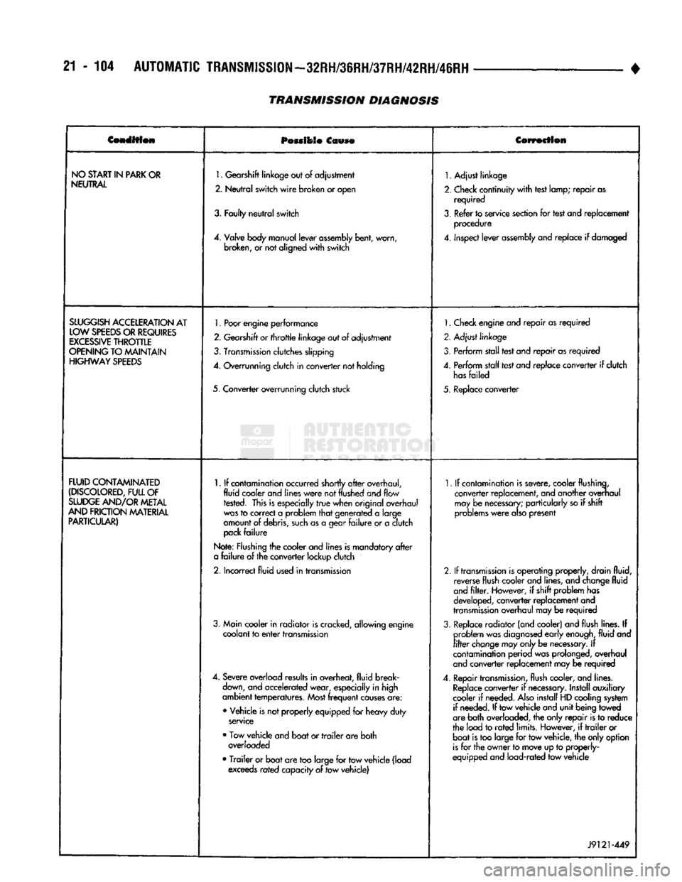
21 - 104
AUTOMATIC
TRANSMISSION—32RH/36RH/37RH/42RH/46RH
•
Condition
POMIOSO
Ccwse
Correction
NO
START
IN
PARK
OR
NEUTRAL
1.
Gearshift
linkage
out
of
adjustment
2.
Neutral
switch
wire
broken
or
open
3.
Faulty
neutral
switch
4.
Valve
body
manual
lever
assembly
bent,
worn,
broken,
or not
aligned
with
switch
1.
Adjust linkage
2.
Check continuity
with
test lamp; repair as required
3.
Refer to service section for test and replacement procedure
4.
inspect lever
assembly
and replace if damaged
SLUGGISH
ACCELERATION
AT
LOW
SPEEDS
OR
REQUIRES
EXCESSIVE
THROTTLE
OPENING
TO MAINTAIN
HIGHWAY
SPEEDS
1.
Poor
engine
performance
2.
Gearshift
or
throttle
linkage
out of adjustment
3.
Transmission
clutches slipping
4.
Overrunning clutch in converter not holding
5. Converter overrunning clutch stuck
1.
Check engine and repair as required
2. Adjust linkage
3. Perform stall test and repair as required
4.
Perform stall test and replace converter if clutch
has
failed
5. Replace converter
FLUID
CONTAMINATED
(DISCOLORED,
FULL
OF
SLUDGE
AND/OR
METAL
AND
FRICTION
MATERIAL
PARTICULAR)
1.
If contamination occurred shortly
after
overhaul,
fluid cooler and
lines
were
not
flushed
and flow rested. This is especially
true
when original overhaul
was
to correct a problem
that
generated a large
amount of debris,
such
as a gear
failure
or a clutch
pack
failure
Note: Flushing the cooler and lines is mandatory
after
a
failure
of the converter lockup clutch
2.
Incorrect fluid used in transmission
3. Main cooler in radiator is cracked, allowing engine coolant to
enter
transmission
4.
Severe overload results in overheat, fluid break
down,
and accelerated wear, especially in high
ambient temperatures.
Most
frequent
causes
are:
• Vehicle is not properly equipped for heavy duty
service
• Tow vehicle and boat or
trailer
are both overloaded
•
Trailer
or boat are too large for tow vehicle (load exceeds rated capacity of tow vehicle)
1.
If contamination is severe, cooler flushing,
converter replacement, and another overhaul may be
necessary;
particularly so if shift
problems
were
also
present
2.
If
transmission
is operating properly, drain fluid, reverse flush cooler and lines, and change fluid
and
filter.
However, if shift problem has
developed, converter replacement and
transmission
overhaul may be required
3.
Replace radiator (and cooler) and flush lines. If problem was
diagnosed
early
enough,
fluid and
filter
change
may
only
be
necessary.
If
contamination perioa was prolonged, overhaul
and
converter replacement may be required
4.
Repair
transmission,
flush cooler, and lines.
Replace
converter if
necessary.
Install auxiliary
cooler if needed.
Also
install HD cooling system if needed. If tow vehicle and unit being towed
are both overloaded, the only repair is to reduce
the load to
rated
limits. However, if
trailer
or boat is too large for tow vehicle, the only option
is
for the owner to move up to properly-
equipped and load-rated tow vehicle
J9121-449
TRANSMISSION DIAGNOSIS
Page 1106 of 1502
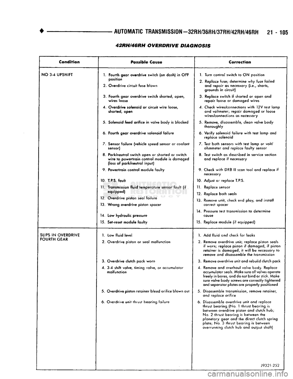
•
AUTOMATIC
TRANSMISSION—32RH/36RH/37RH/42RH/46RH
21-105 Condition
Possible
Co
use
Correction
NO
3-4 UPSHIFT
1.
Fourth
gear overdrive
switch
(on dash) in
OFF
1.
Turn control
switch
to ON position
2.
position
Overdrive
circuit
fuse
blown
2. Replace fuse; determine why fuse failed
and
repair as necessary
(i.e.,
shorts,
grounds
in
circuit)
3.
Fourth
gear
overdrive
switch
shorted, open,
wires
loose 3. Replace switch if shorted or open and
repair loose or damaged wires
4. Overdrive solenoid or circuit
wire
loose,
shorted, open 4. Check wires/connections
with
12V test lamp
and
voltmeter; repair damaged or loose
wires/connections as necessary
5. Solenoid
feed
orifice
in valve body is
blocked
5. Remove, disassemble, clean valve body
thoroughly
6.
Fourth
gear
overdrive
solenoid
failure
6. Verify solenoid
failure
with
test lamp and
replace solenoid
7.
Sensor
failure
(vehicle speed sensor or coolant
sensor)
7. Test both
sensors
with
test lamp or volt/
ohmmeter and replace
faulty
sensor
8. Park/neutral switch open or
shorted
or
switch
wire
to
powertrain
control
module is damaged
(loss
of park/neutral
input)
8. Test switch as described in service section
and
replace if necessary
9.
Powertrain
control module
faulty
9. Check
with
DRB II
scan
tool and replace if
necessary
10.
T.P.S.
fault
10. Adjust or replace
T.P.S.
11.
Transmission fluid
temperature
sensor
fault
(if equipped)
12. Overdrive piston seal
failure
13. Wrong
overdrive
piston
spacer
11.
Replace sensor
12. Replace both
seals
13. Remove unit, check end play, and install correct spacer
14.
Low
hydraulic pressure 14. Pressure test transmission to determine
cause
15. Set-reset module
faulty
15. Replace module (if equipped)
SUPS
IN
OVERDRIVE
FOURTH
GEAR
1.
2. Low
fluid
level
Overdrive piston or seal
malfunction
1.
Add fluid and check for leaks
2. Remove overdrive unit; replace piston
seals
if worn; replace piston if damaged, if piston
retainer
is damaged, it
will
be necessary to
remove and disassemble the transmission
3. Overdrive clutch pack
worn
3. Remove overdrive unit and rebuild clutch pack
4. 3-4
shift
valve,
timing
valve, or accumulator
malfunction
4. Remove and overhaul valve body. Replace
accumulator
seals.
Make sure all valves operate
freely
in bores, and do not bind or stick. Make
sure
valve body screws are correctly tightened
and
separator plates are properly positioned
5. Overdrive
piston
retainer
bleed
orifice
blown out 5. Disassemble transmission, remove
retainer,
and
replace orifice
6. Overdrive
unit
thrust
bearing
failure
6. Disassemble overdrive unit and replace
thrust bearing (No. 1 thrust bearing is between overdrive piston and clutch hub;
No.
2 thrust bearing is between the
planetary gear and the direct clutch spring plate; No. 3
thrust
bearing is between
overrunning clutch hub and output shaft)
J9321-252
42RH/46RH OVERDRIVE DIAGNOSIS
Page 1107 of 1502
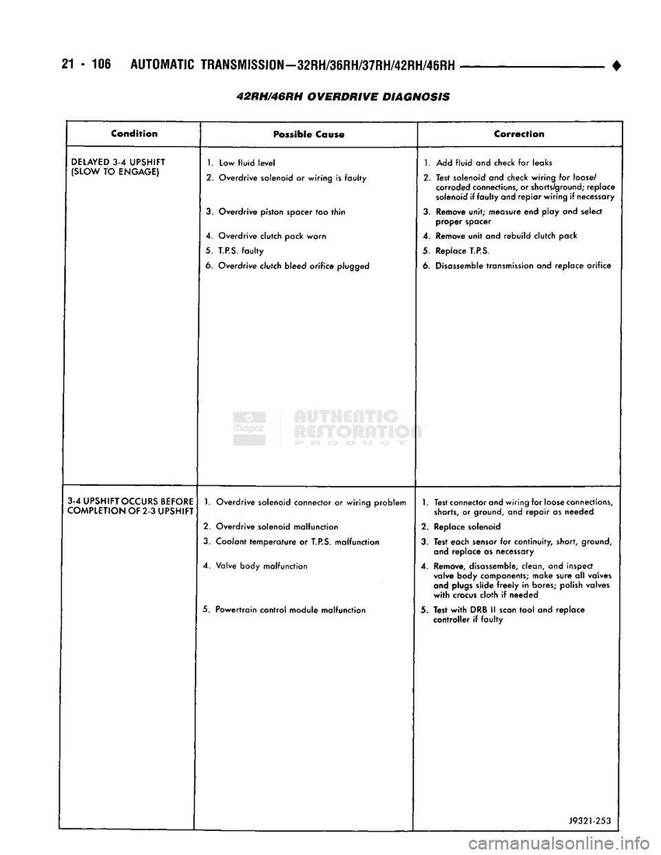
21-106
AUTOMATIC
TRANSMISSION—32RH/36RH/37RH/42RH/46RH
42RH/46RH OVERDRIVE DIAGNOSIS •
Condition
Possible
Cause
Correction
DELAYED
3-4
UPSHIFT
(SLOW
TO
ENGAGE)
1.
Low fluid
level
2. Overdrive solenoid or wiring is faulty
3.
Overdrive piston spacer too thin
4. Overdrive clutch pack worn
5.
T.P.S.
faulty
6. Overdrive clutch bleed orifice
plugged
1.
Add fluid and check for leaks
2. Test solenoid and check wiring for
loose/
corroded
connections,
or
shorts/ground;
replace
solenoid
if faulty and repiar wiring if
necessary
3.
Remove unit; measure end play and select proper spacer
4. Remove unit and rebuild clutch pack
5. Replace
T.P.S.
6.
Disassemble
transmission
and replace orifice
3-4
UPSHIFT
OCCURS
BEFORE
COMPLETION
OF 2-3
UPSHIFT
1.
Overdrive solenoid connector or wiring problem
2. Overdrive solenoid malfunction
3.
Coolant temperature or
T.P.S.
malfunction
4. Valve body malfunction
5. Powertrain control module malfunction
1.
Test connector and wiring for
loose
connections,
shorts,
or
ground,
and repair as needed
2. Replace solenoid
3.
Test each
sensor
for continuity, short,
ground,
and
replace as necessary
4. Remove,
disassemble,
clean, and inspect
valve
body components; make sure all valves
and
plugs
slide
freely
in bores; polish valves
with
crocus
cloth if needed
3. Test
with
DRB II
scan
tool and replace controller if faulty
J9321-253
Page 1131 of 1502
21
-
130
IN-VEHICLE
SERVICE-~32RH/36RH/37RH/42RH/4iRH
•
IN-VEHICLE
SERVICE-32RH/36RH/37RH/42RH/46RH
INDEX
page
Aluminum Thread Repair
141
Checking
Fluid
Level
130
Extension Housing Bushing
and
Output
Shaft
Bearing
Service-32RH/36RH/37RH
... .
135
Extension Housing Yoke Seal Replacement
....
135
Fluid
and Filter
Change
130
Front
Band
Adjustment
133
Gearshift Linkage
Adjustment
130
Governor
and
Park Gear Service—
32RH/36RH/37RH
137
Governor
and
Park Lock Service—42RH/46RH
.
138
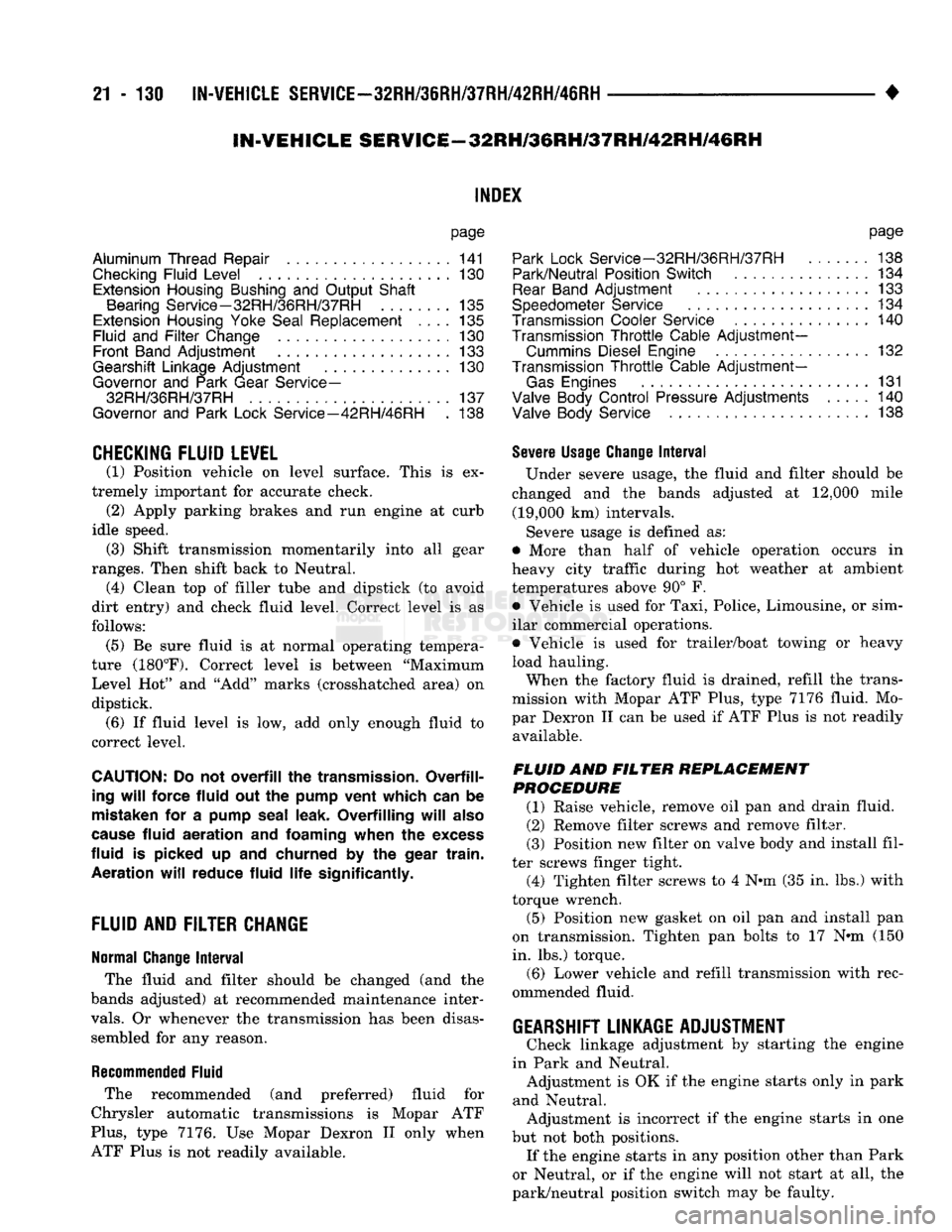
CHECKING
FLUID LEVEL
(1) Position vehicle
on
level surface. This
is ex
tremely important
for
accurate check.
(2)
Apply parking brakes
and run
engine
at
curb
idle speed.
(3)
Shift transmission momentarily into
all
gear
ranges. Then shift back
to
Neutral.
(4)
Clean
top of
filler tube
and
dipstick
(to
avoid
dirt entry)
and
check fluid level. Correct level
is as
follows:
(5)
Be
sure fluid
is at
normal operating tempera
ture (180°F). Correct level
is
between "Maximum Level
Hot"
and
"Add"
marks (crosshatched area)
on
dipstick. (6)
If
fluid level
is
low,
add
only enough fluid
to
correct level.
CAUTION:
Do not
overfill
the
transmission. Overfilling
will
force fluid
out
the
pump vent which
can
be
mistaken
for
a
pump seal leak. Overfilling
will
also
cause
fluid aeration
and foaming
when
the
excess
fluid
is
picked
up
and
churned
by
the
gear train. Aeration
will
reduce fluid
life
significantly.
FLUID
AND
FILTER
CHANGE
Normal Change
Interval
The fluid
and
filter should
be
changed
(and the
bands adjusted)
at
recommended maintenance inter
vals.
Or
whenever
the
transmission
has
been disassembled
for
any
reason.
Recommended Fluid
The recommended
(and
preferred) fluid
for
Chrysler automatic transmissions
is
Mopar
ATF
Plus,
type
7176.
Use
Mopar Dexron
II
only when
ATF Plus
is not
readily available.
page
Park Lock
Service-32RH/36RH/37RH
. 138
Park/Neutral Position Switch
134
Rear
Band
Adjustment
133
Speedometer Service
134
Transmission Cooler Service
140
Transmission
Throttle
Cable
Adjustment-
Cummins Diesel Engine
132
Transmission
Throttle
Cable
Adjustment-
Gas
Engines
131
Valve Body
Control
Pressure Adjustments
.....
140
Valve Body Service
138
Severe Usage Change
Interval
Under severe usage,
the
fluid
and
filter should
be
changed
and the
bands adjusted
at
12,000 mile (19,000
km)
intervals.
Severe usage
is
defined
as:
• More than half
of
vehicle operation occurs
in
heavy city traffic during
hot
weather
at
ambient
temperatures above
90°
F.
• Vehicle
is
used
for
Taxi, Police, Limousine,
or
sim
ilar commercial operations.
• Vehicle
is
used
for
trailer/boat towing
or
heavy
load hauling. When
the
factory fluid
is
drained, refill
the
trans
mission with Mopar
ATF
Plus, type
7176
fluid.
Mo
par Dexron
II
can
be
used
if
ATF
Plus
is
not
readily available.
FLUID
AND
FILTER
REPLACEMENT
PROCEDURE
(1) Raise vehicle, remove
oil pan
and
drain fluid.
(2) Remove filter screws
and
remove filter.
(3) Position
new
filter
on
valve body
and
install fil
ter screws finger tight. (4) Tighten filter screws
to 4
N*m (35
in.
lbs.)
with
torque wrench.
(5) Position
new
gasket
on oil pan
and
install
pan
on transmission. Tighten
pan
bolts
to 17
N»m
(150
in.
lbs.)
torque. (6) Lower vehicle
and
refill transmission with rec
ommended fluid.
GEARSHIFT LINKAGE ADJUSTMENT
Check linkage adjustment
by
starting
the
engine
in Park
and
Neutral. Adjustment
is
OK
if
the
engine starts only
in
park
and Neutral. Adjustment
is
incorrect
if
the
engine starts
in one
but
not
both positions. If
the
engine starts
in
any
position other than Park
or Neutral,
or if
the
engine will
not
start
at
all,
the
park/neutral position switch
may
be
faulty.
Page 1134 of 1502
•
IN-VEHICLE SERVICE-32RH/36RH/37RH/42RH/46RH
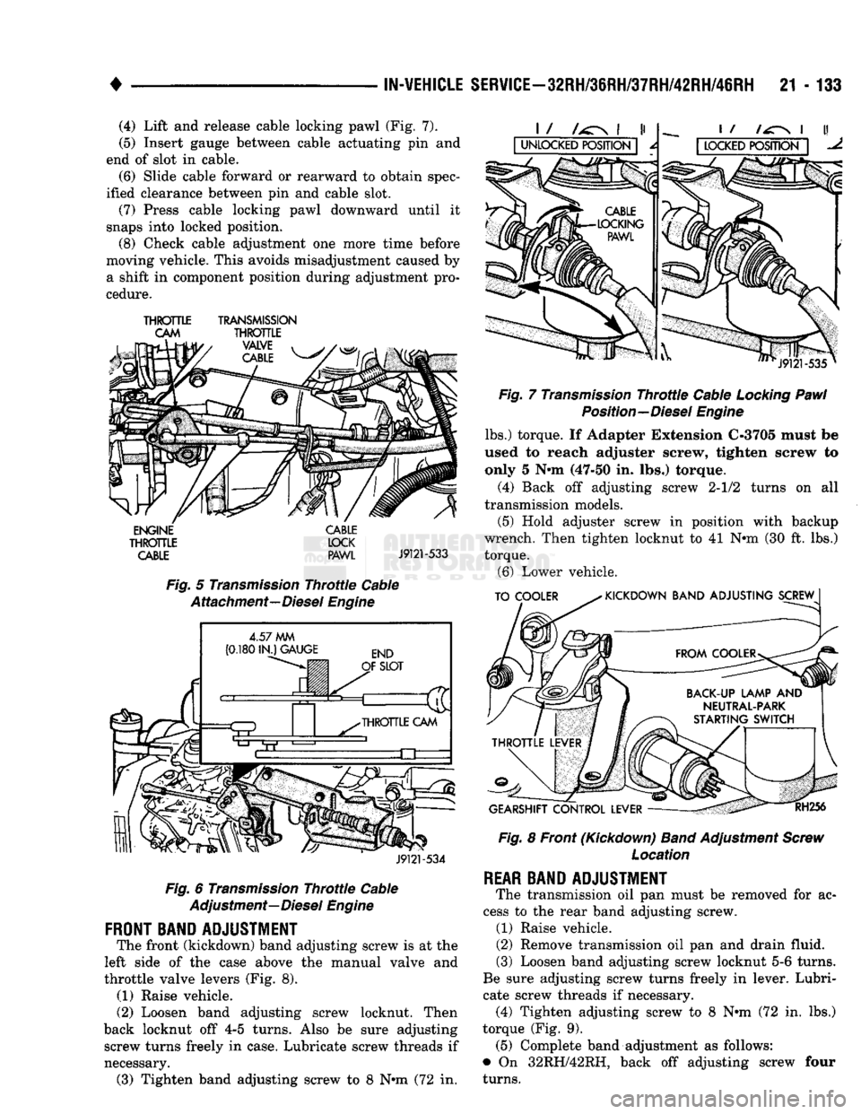
21 - 133 (4) Lift and release cable locking pawl (Fig. 7).
(5) Insert gauge between cable actuating pin and
end of slot in cable. (6) Slide cable forward or rearward to obtain spec
ified clearance between pin and cable slot.
(7) Press cable locking pawl downward until it
snaps into locked position.
(8) Check cable adjustment one more time before
moving vehicle. This avoids misadjustment caused by
a shift in component position during adjustment pro
cedure.
THROTTLE
TRANSMISSION
CAM
THROTTLE
VALVE
i j
/\&s/,
CABLE
m
ENGINE
THROTTLE
CABLE CABLE
LOCK PAWL
J9121-533
Fig.
5
Transmission
Throttle
Cable
Attachment—Diesel
Engine
4.57
MM
(0.180
IN.) GAUGE
J9121-534
Fig.
6
Transmission
Throttle
Cable
Adjustment—Diesel
Engine
FRONT BAND ADJUSTMENT
The front (kickdown) band adjusting screw is at the
left side of the case above the manual valve and
throttle valve levers (Fig. 8). (1) Raise vehicle.
(2) Loosen band adjusting screw locknut. Then
back locknut off 4-5 turns. Also be sure adjusting screw turns freely in case. Lubricate screw threads if
necessary. (3) Tighten band adjusting screw to 8 Nrm (72 in.
J9121
-535
Fig.
7
Transmission
Throttle
Cable
Locking
Pawl
Position—Diesel
Engine
lbs.) torque. If Adapter Extension C-3705 must be
used to reach adjuster screw, tighten screw to only 5 N»m (47-50 in. lbs.) torque.
(4) Back off adjusting screw 2-1/2 turns on all
transmission models. (5) Hold adjuster screw in position with backup
wrench. Then tighten locknut to 41 N»m (30 ft. lbs.)
torque. (6) Lower vehicle.
TO COOLER
KICKDOWN BAND ADJUSTING SCREW
GEARSHIFT CONTROL LEVER
RH256
Fig.
8 Front (Kickdown)
Band
Adjustment
Screw
Location
REAR
BAND ADJUSTMENT
The transmission oil pan must be removed for ac
cess to the rear band adjusting screw. (1) Raise vehicle.
(2) Remove transmission oil pan and drain fluid.
(3) Loosen band adjusting screw locknut 5-6 turns.
Be sure adjusting screw turns freely in lever. Lubri
cate screw threads if necessary. (4) Tighten adjusting screw to 8 Nnn (72 in. lbs.)
torque (Fig. 9). (5) Complete band adjustment as follows:
• On 32RH/42RH, back off adjusting screw four
turns.
Page 1135 of 1502
21
- 134
IN-WEHiCLE SER¥iCE-32RH/3IRH/37RH/42RH/46RH
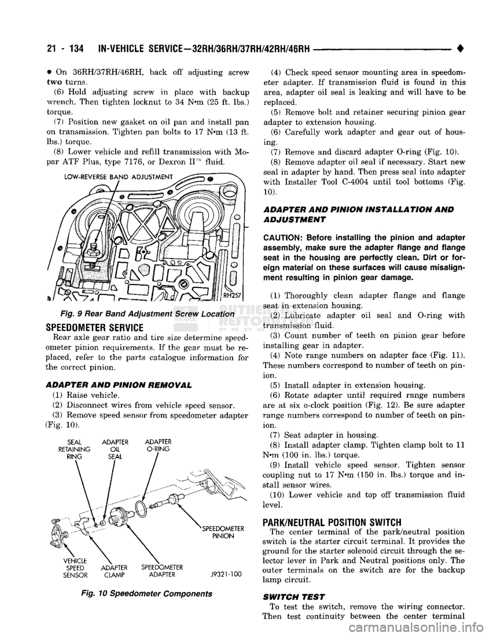
• • On 36RH/37RH746RH, back off adjusting screw
two turns. (6) Hold adjusting screw in place with backup
wrench. Then tighten locknut to 34 N*m (25 ft. lbs.) torque.
(7) Position new gasket on oil pan and install pan
on transmission. Tighten pan bolts to 17 N»m (13 ft.
lbs.) torque.
(8) Lower vehicle and refill transmission with Mo
par ATF Plus, type 7176, or Dexron II™ fluid.
Fig. § Rear Band Adjustment Screw Location
SPEEDOMETER
SERVICE
Rear axle gear ratio and tire size determine speed
ometer pinion requirements. If the gear must be re
placed, refer to the parts catalogue information for
the correct pinion.
ADAPTER
AND
PINION REMOWAL
(1) Raise vehicle.
(2) Disconnect wires from vehicle speed sensor.
(3) Remove speed sensor from speedometer adapter
(Fig. 10). SEAL ADAPTER ADAPTER
RETAINING OIL O-RING
SPEED ADAPTER SPEEDOMETER
SENSOR CLAMP ADAPTER J932M00
Fig. 10 Speedometer Components (4) Check speed sensor mounting area in speedom
eter adapter. If transmission fluid is found in this area, adapter oil seal is leaking and will have to be
replaced. (5) Remove bolt and retainer securing pinion gear
adapter to extension housing. (6) Carefully work adapter and gear out of hous
ing. (7) Remove and discard adapter O-ring (Fig. 10).
(8) Remove adapter oil seal if necessary. Start new
seal in adapter by hand. Then press seal into adapter
with Installer Tool C-4004 until tool bottoms (Fig.
10).
ADAPTER AND PINION INSTALLATION AND
ADJUSTMENT
CAUTION:
Before installing
the
pinion
and
adapter
assembly,
make sure
the
adapter flange
and
flange
seat
in the
housing
are
perfectly clean. Dirt
or
for
eign
material
on
these surfaces
will
cause misalign ment resulting
in
pinion gear damage.
(1) Thoroughly clean adapter flange and flange
seat in extension housing.
(2) Lubricate adapter oil seal and O-ring with
transmission fluid.
(3) Count number of teeth on pinion gear before
installing gear in adapter.
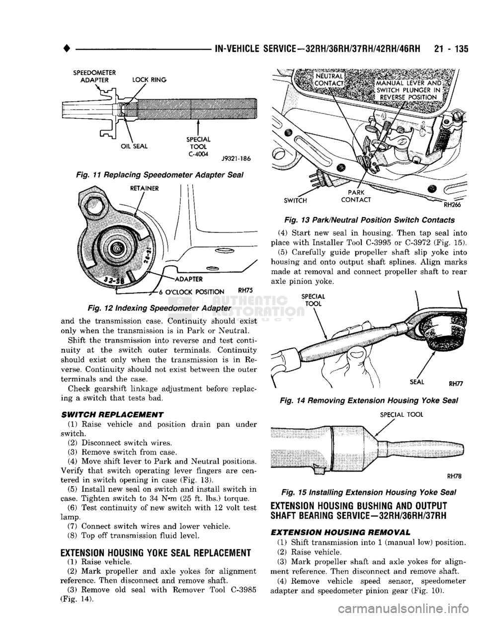
(4) Note range numbers on adapter face (Fig. 11).
These numbers correspond to number of teeth on pin ion.
(5) Install adapter in extension housing.
(6) Rotate adapter until required range numbers
are at six o-clock position (Fig. 12). Be sure adapter
range numbers correspond to number of teeth on pin ion.
(7) Seat adapter in housing.
(8) Install adapter clamp. Tighten clamp bolt to 11
N*m (100 in. lbs.) torque.
(9) Install vehicle speed sensor. Tighten sensor
coupling nut to 17 N*m (150 in. lbs.) torque and in
stall sensor wires.
(10) Lower vehicle and top off transmission fluid
level.
PARK/NEUTRAL
POSITION SWJTCH
The center terminal of the park/neutral position
switch is the starter circuit terminal. It provides the
ground for the starter solenoid circuit through the se
lector lever in Park and Neutral positions only. The
outer terminals on the switch are for the backup
lamp circuit.
SWITCH TEST To test the switch, remove the wiring connector.
Then test continuity between the center terminal
Page 1136 of 1502
•
IN-VEHICLE
SERVICE-32RH/3eRH/37RH/42RH/46RH
21 - 135
SPEEDOMETER
ADAPTER
LOCK
RING
OIL
SEAL
SPECIAL
TOOL
C-4004
J9321-186
Fig. 11 Replacing Speedometer Adapter Seal
RETAINER
-ADAPTER
-7^6
O'CLOCK
POSITION
RH75
Fig.
12 Indexing Speedometer Adapter
and the transmission case. Continuity should exist
only when the transmission is in Park or Neutral.
Shift the transmission into reverse and test conti
nuity at the switch outer terminals. Continuity should exist only when the transmission is in Re
verse. Continuity should not exist between the outer
terminals and the case.
Check gearshift linkage adjustment before replac
ing a switch that tests bad.
SWITCH
REPLACEMENT
(1) Raise vehicle and position drain pan under
switch. (2) Disconnect switch wires.
(3) Remove switch from case.
(4) Move shift lever to Park and Neutral positions.
Verify that switch operating lever fingers are cen
tered in switch opening in case (Fig. 13).
(5) Install new seal on switch and install switch in
case.
Tighten switch to 34 Nnn (25 ft. lbs.) torque. (6) Test continuity of new switch with 12 volt test
lamp.
(7) Connect switch wires and lower vehicle.
(8) Top off transmission fluid level.
EXTENSION HOUSING
YOKE
SEAL REPLACEMENT (1) Raise vehicle.
(2) Mark propeller and axle yokes for alignment
reference. Then disconnect and remove shaft. (3) Remove old seal with Remover Tool C-3985
(Fig. 14).
SWITCH
RH266
Fig.
13 Park/Neutral Position
Switch
Contacts (4) Start new seal in housing. Then tap seal into
place with Installer Tool
C-3995
or
C-3972
(Fig. 15).
(5)
Carefully guide propeller shaft slip yoke into
housing and onto output shaft splines. Align marks made at removal and connect propeller shaft to rear
axle pinion yoke.
SPECIAL
TOOL
Fig.
14
Removing
Extension
Housing
Yoke
Seal
SPECIAL
TOOL
RH78
Fig.
15 Installing Extension
Housing
Yoke
Seal
EXTENSION HOUSING BUSHING AND OUTPUT
SHAFT BEARING
SERVlCE-32RH/3eRH/37RH
EXTENSION
HOUSING
REMOVAL
(1) Shift transmission into 1 (manual low) position.
(2) Raise vehicle.
(3) Mark propeller shaft and axle yokes for align
ment reference. Then disconnect and remove shaft. (4) Remove vehicle speed sensor, speedometer
adapter and speedometer pinion gear (Fig. 10).
Page 1139 of 1502
21
- 138
IN-VEHICLE SERVSCE-32RH/36RH/37RH/42RH/46RH
(2) Install and tighten gear-to-body bolts finger
tight. Make sure oil passage in governor body aligns
with matching passage in gear. (3) Install assembled governor body and gear on
output shaft.
(4) Position governor body so valve shaft hole in
body aligns with matching hole in output shaft. Then slide body and park gear into place. (5) Install snap ring securing governor and park
gear to output shaft (Fig. 22).
(6) Tighten bolts attaching governor body to park
gear to 11 N»m (95 in. lbs.) torque.
(7) Assemble governor weights and spring. Secure
inner weight and spring in outer weight with snap
ring (Fig. 21).
(8) Install weight assembly in governor body and
install retaining snap ring (Fig. 21).
(9) Place governor valve on valve shaft. Insert shaft
in governor body, through governor weights and output
shaft. Be sure valve is properly seated in body.
(10) Secure valve shaft with small snap ring.
(11) Install output shaft bearing and extension
housing. Refer to procedure in this section.
GOVERNOR
AND
PARK LOCK SERVICE—42RH/
46RH
The governor and park lock components are located
within the overdrive unit and cannot be serviced in
the vehicle. The overdrive unit must be removed and disassem
bled for access to the governor and park lock compo
nents.
Refer to the 42RH/46RH overdrive unit service sec
tions for repair procedures.
PARK
LOCK SERVICE—32RH/36RH/37RH
PARK LOCK
COMPONENT REMOVAL
(1) Remove extension housing as described in this
section. (2) Slide sprag shaft out of extension housing and
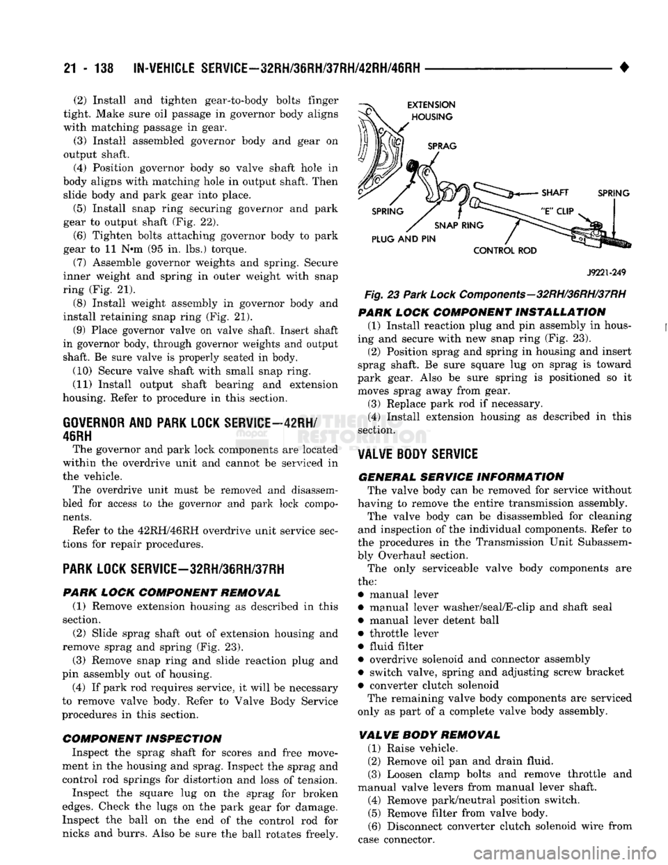
remove sprag and spring (Fig. 23).
(3) Remove snap ring and slide reaction plug and
pin assembly out of housing. (4) If park rod requires service, it will be necessary
to remove valve body. Refer to Valve Body Service
procedures in this section.
COMPONENT INSPECTION
Inspect the sprag shaft for scores and free move
ment in the housing and sprag. Inspect the sprag and control rod springs for distortion and loss of tension.
Inspect the square lug on the sprag for broken
edges.
Check the lugs on the park gear for damage. Inspect the ball on the end of the control rod for
nicks and burrs. Also be sure the ball rotates freely.
J9221-249
Fig. 23
Park
Lock Components-32RH/36RH/37RH
PARK
LOCK
COMPONENT INSTALLATION
(1) Install reaction plug and pin assembly in hous
ing and secure with new snap ring (Fig. 23).
(2) Position sprag and spring in housing and insert
sprag shaft. Be sure square lug on sprag is toward
park gear. Also be sure spring is positioned so it moves sprag away from gear.
(3) Replace park rod if necessary. (4) Install extension housing as described in this
section.
VALVE BODY
SERVICE
GENERAL SERVICE
INFORMATION
The valve body can be removed for service without
having to remove the entire transmission assembly. The valve body can be disassembled for cleaning
and inspection of the individual components. Refer to
the procedures in the Transmission Unit Subassem
bly Overhaul section.
The only serviceable valve body components are
the:
• manual lever
• manual lever washer/seal/E-clip and shaft seal
• manual lever detent ball
• throttle lever
• fluid filter
• overdrive solenoid and connector assembly
• switch valve, spring and adjusting screw bracket • converter clutch solenoid The remaining valve body components are serviced
only as part of a complete valve body assembly.
VALVE
BODY
REMOVAL
(1) Raise vehicle.
(2) Remove oil pan and drain fluid.
(3) Loosen clamp bolts and remove throttle and
manual valve levers from manual lever shaft. (4) Remove park/neutral position switch. (5) Remove filter from valve body.
(6) Disconnect converter clutch solenoid wire from
case connector.