maintenance DODGE TRUCK 1993 Service Owner's Guide
[x] Cancel search | Manufacturer: DODGE, Model Year: 1993, Model line: TRUCK, Model: DODGE TRUCK 1993Pages: 1502, PDF Size: 80.97 MB
Page 51 of 1502
0
- 32
LUBRICATION
AND
MAINTENANCE
•
Fig.
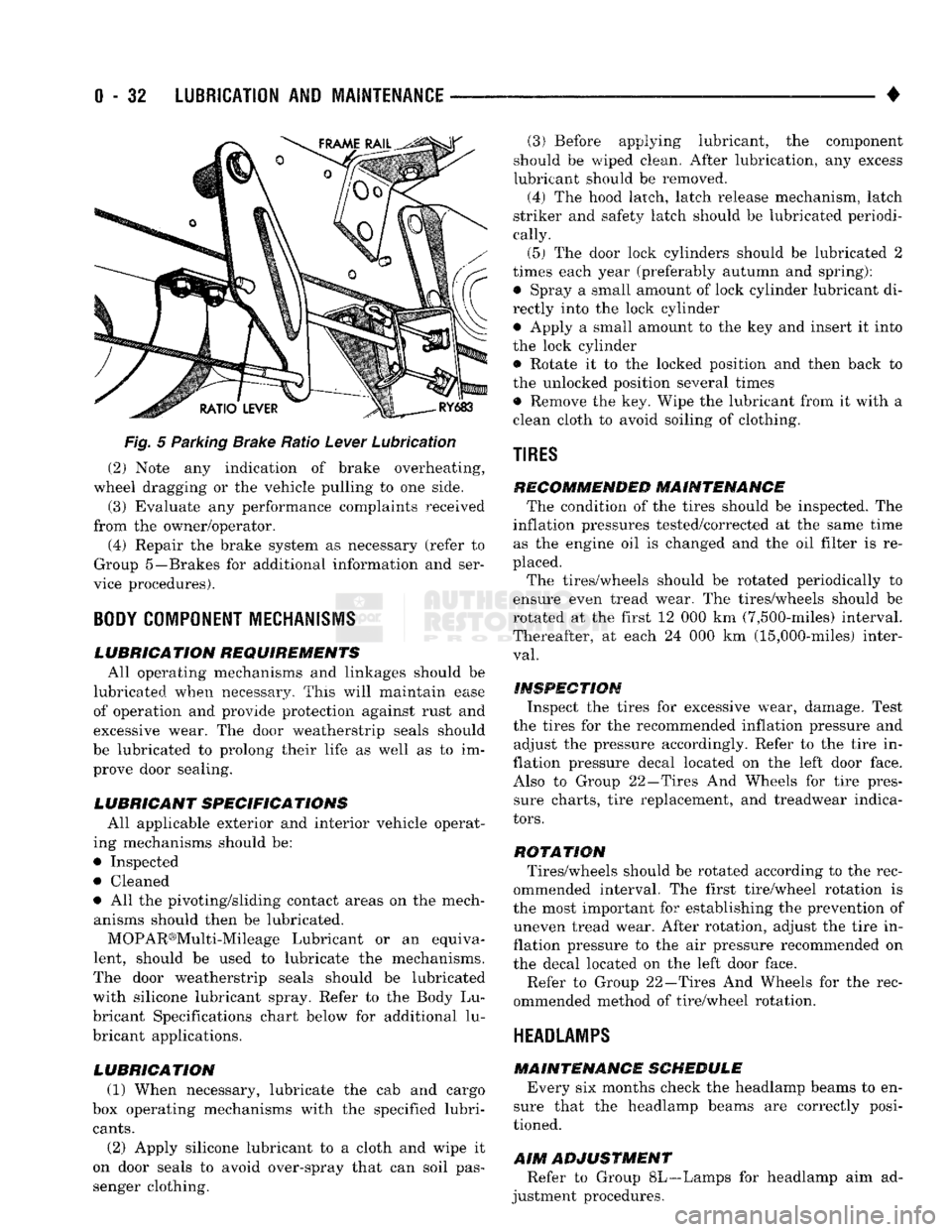
5 Parking Brake Ratio Lever Lubrication (2) Note any indication of brake overheating,
wheel dragging or the vehicle pulling to one side.
(3) Evaluate any performance complaints received
from the owner/operator. (4) Repair the brake system as necessary (refer to
Group 5—Brakes for additional information and ser
vice procedures).
BODY
COMPONENT
MECHANISMS
LUBRICATION REQUIREMENTS
All operating mechanisms and linkages should be
lubricated when necessary. This will maintain ease of operation and provide protection against rust and
excessive wear. The door weatherstrip seals should
be lubricated to prolong their life as well as to im prove door sealing.
LUBRICANT SPECIFICATIONS
All applicable exterior and interior vehicle operat
ing mechanisms should be:
• Inspected • Cleaned
• All the pivoting/sliding contact areas on the mech anisms should then be lubricated.
MOPAR®Multi-Mileage Lubricant or an equiva
lent, should be used to lubricate the mechanisms.
The door weatherstrip seals should be lubricated
with silicone lubricant spray. Refer to the Body Lu
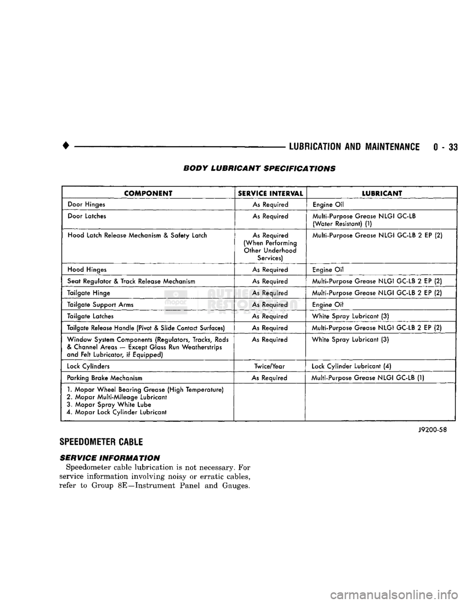
bricant Specifications chart below for additional lu
bricant applications.
LUBRICATION
(1) When necessary, lubricate the cab and cargo
box operating mechanisms with the specified lubri
cants.
(2) Apply silicone lubricant to a cloth and wipe it
on door seals to avoid over-spray that can soil pas
senger clothing. (3) Before applying lubricant, the component
should be wiped clean. After lubrication, any excess
lubricant should be removed.
(4) The hood latch, latch release mechanism, latch
striker and safety latch should be lubricated periodi
cally.
(5) The door lock cylinders should be lubricated 2
times each year (preferably autumn and spring): • Spray a small amount of lock cylinder lubricant di
rectly into the lock cylinder
• Apply a small amount to the key and insert it into
the lock cylinder • Rotate it to the locked position and then back to
the unlocked position several times
• Remove the key. Wipe the lubricant from it with a
clean cloth to avoid soiling of clothing.
TIRES
RECOMMENDED MAINTENANCE
The condition of the tires should be inspected. The
inflation pressures tested/corrected at the same time as the engine oil is changed and the oil filter is re
placed.
The tires/wheels should be rotated periodically to
ensure even tread wear. The tires/wheels should be
rotated at the first 12 000 km (7,500-miles) interval.
Thereafter, at each 24 000 km (15,000-miles) inter
val.
INSPECTION
Inspect the tires for excessive wear, damage. Test
the tires for the recommended inflation pressure and adjust the pressure accordingly. Refer to the tire in
flation pressure decal located on the left door face. Also to Group 22—Tires And Wheels for tire pressure charts, tire replacement, and treadwear indica
tors.
ROTATION
Tires/wheels should be rotated according to the rec
ommended interval. The first tire/wheel rotation is
the most important for establishing the prevention of uneven tread wear. After rotation, adjust the tire in
flation pressure to the air pressure recommended on
the decal located on the left door face.
Refer to Group 22—Tires And Wheels for the rec
ommended method of tire/wheel rotation.
HEADLAMPS
MAINTENANCE SCHEDULE
Every six months check the headlamp beams to en
sure that the headlamp beams are correctly posi
tioned.
AIM
ADJUSTMENT
Refer to Group 8L—Lamps for headlamp aim ad
justment procedures.
Page 52 of 1502
•
LUBRICATION
AND
MAINTENANCE
0 - 33 BODY LUBRICANT SPECIFICATIONS
COMPONENT
SERVICE
INTERVAL
LUBRICANT
Door
Hinges
As
Required
Engine
Oil
Door
Latches
As
Required Multi-Purpose Grease
NLGI
GC-LB
(Water
Resistant)
(1)
Hood
Latch Release Mechanism
&
Safety Latch
As
Required
(When Performing Other Underhood Services) Multi-Purpose Grease
NLGI
GC-LB
2
EP
(2)
Hood
Hinges
As
Required
Engine
Oil
Seat Regulator
&
Track Release Mechanism
As
Required Multi-Purpose Grease
NLGI
GC-LB
2
EP
(2)
Tailgate Hinge
As
Required Multi-Purpose Grease
NLGI
GC-LB
2
EP
(2)
Tailgate Support Arms
As
Required
Engine
Oil
Tailgate Latches
As
Required
White
Spray Lubricant
(3)
Tailgate Release Handle (Pivot & Slide Contact Surfaces)
As
Required Multi-Purpose Grease
NLGI
GC-LB
2
EP
(2)
Window System Components (Regulators, Tracks,
Rods
&
Channel Areas — Except
Glass
Run Weatherstrips
and
Felt
Lubricator,
if
Equipped)
As
Required
White
Spray Lubricant
(3)
Lock
Cylinders Twice/Year
Lock
Cylinder Lubricant
(4)
Parking Brake Mechanism
As
Required Multi-Purpose Grease
NLGI
GC-LB
(1)
1.
Mopar
Wheel
Bearing Grease (High
Temperature)
2. Mopar Multi-Mileage Lubricant 3. Mopar Spray
White
Lube
4. Mopar Lock Cylinder Lubricant
J9200-58
SPEEDOMETER
CABLE
SERVICE INFORMATION Speedometer cable lubrication is not necessary. For
service information involving noisy or erratic cables,
refer to Group 8E—Instrument Panel and Gauges.
Page 56 of 1502
FRONT SUSPENSION
AND
AXLE
2 - 3
FRONT
WHEEL
ALIGNMENT
GENERAL
INFORMATION
Front wheel alignment involves
the
correct posi
tioning
of the
tire contact patch
in
relation
to the
pavement.
The
positioning
is
accomplished through
the suspension
and
steering linkage adjustments.
An
alignment
is
essential
for
efficient steering
and
direc
tional stability.
The
most important factors
of
front
end alignment
are
camber, caster
and toe
position. Routine inspection
of
the front
suspension
and
steering components
is a
good
preventative
maintenance practice.
Inspection
also
helps
to
ensure
safe operation
of the
vehicle.
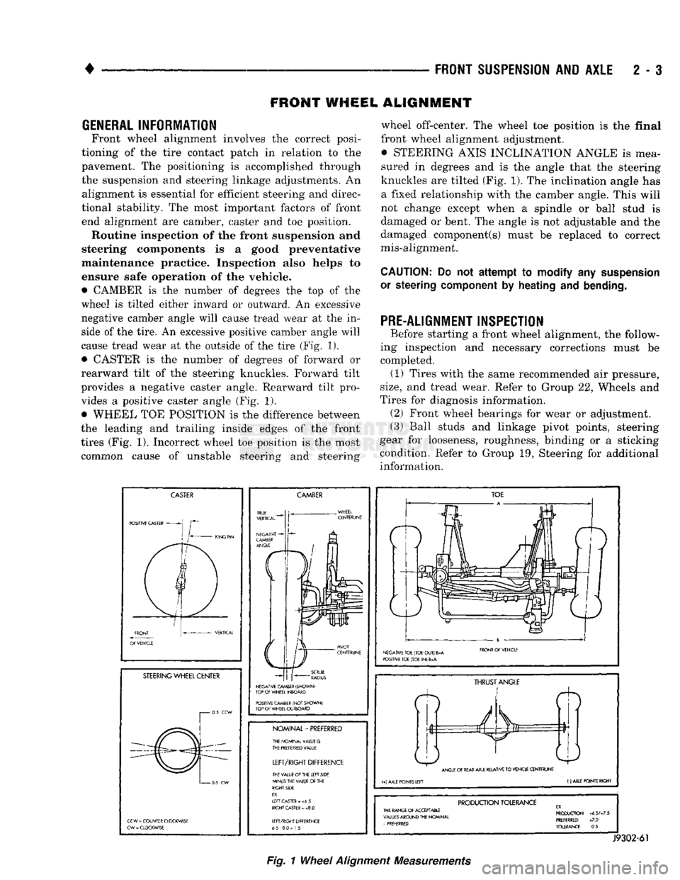
• CAMBER
is the
number
of
degrees
the top of the
wheel
is
tilted either inward
or
outward.
An
excessive
negative camber angle will cause tread wear
at the in
side
of
the tire.
An
excessive positive camber angle will
cause tread wear
at the
outside
of
the tire (Fig.
1),
• CASTER
is the
number
of
degrees
of
forward
or
rearward tilt
of the
steering knuckles. Forward tilt
provides
a
negative caster angle. Rearward tilt pro vides
a
positive caster angle
(Fig. 1).
• WHEEL
TOE
POSITION
is the
difference between
the leading
and
trailing inside edges
of the
front
tires (Fig.
1).
Incorrect wheel
toe
position
is the
most common cause
of
unstable steering
and
steering wheel off-center.
The
wheel
toe
position
is the
final
front wheel alignment adjustment. • STEERING AXIS INCLINATION ANGLE
is
mea
sured
in
degrees
and is the
angle that
the
steering
knuckles
are
tilted (Fig. 1).
The
inclination angle
has
a fixed relationship with
the
camber angle. This will
not change except when
a
spindle
or
ball stud
is
damaged
or
bent.
The
angle
is not
adjustable
and the
damaged component(s) must
be
replaced
to
correct
mis-alignment.
CAUTION:
Do not
attempt to modify
any
suspension
or steering
component
by
heating
and
bending.
PRE-ALIGNMENT INSPECTION
Before starting
a
front wheel alignment,
the
follow
ing inspection
and
necessary corrections must
be
completed.
(1)
Tires with
the
same recommended
air
pressure,
size,
and
tread wear. Refer
to
Group
22,
Wheels
and
Tires
for
diagnosis information. (2) Front wheel bearings
for
wear
or
adjustment.
(3) Ball studs
and
linkage pivot points, steering
gear
for
looseness, roughness, binding
or a
sticking
condition. Refer
to
Group
19,
Steering
for
additional information.
CASTER
POSITIVE CASTER
STEERING
WHEEL CENTER
i 0.5
CCW
0
5
CW
CCW
=
COUNTER CLOCKWISE
CW
-
CLOCKWISE
CAMBER
NEGATIVE CAMBER (SHOWN)
TOP
OF
WHEEL INBOARD
POSITIVE CAMBER
(NOT
SHOWN)
TOP
OF
WHEEL OUTBOARD
NOMINAL-PREFERRED
THE NOMINAL VALUE
IS
THE
PREFERRED
VALUE
LEFT/RIGHT
DIFFERENCE
THE VALUE
Of
THE LEFT SIDE
MINUS THE VALUE
OF
THE
RIGHT SIDE
EX.
If
FT CASTER
- +6 5
RIGHT
CASTER
»
+8.0
LEFT/RIGHT DIFFERENCE
65 8.0
=
1
5
TOE
NEGATIVE TOE (TOE
OUT)
B>A
POSITIVE TOE (TOE
IN) 6
FRONT
Of
VEHICLE
ft
THRUST
ANGLE
ANGLE
OF
REAR
AXLE RELATIVE
TO
VEHICLE CENTERUNE
(+)
AXLE POINTS LEFT
(-)
AXLE POINTS RIGHT
PRODUCTION
TOLERANCE
THE RANGE
Of
ACCEPTABLE
VALUES
AROUND THE NOMINAL
-
PREFERRED PRODUCTION
+6.5A7.5
PREFERRED:
+7.0
TOLERANCE:
0.5
J9302-61
Fig.
1
Wheel
Alignment
Measurements
Page 60 of 1502
•
FRONT
SUSPENSION
AND
AXLE
2 • 7
FRONT SUSPENSION
—2WD
VEHICLES
INDEX
page
Coil Springs
9
Lower Ball Stud
. 10
Lower Suspension
Arm 10
Lower Suspension
Arm
Bushing
11
Lower Suspension
Arm
Strut
8
Service
Information
7
Shock
Absorber
9
page
Stabilizer
Bar 8
Steering Knuckle
13
Upper Ball Stud
11
Upper Suspension
Arm 11
Upper Suspension
Arm
Bushing Replacement
. . . 12
Wheel
Hub and
Bearings
7
SERVICE
INFORMATION
Periodic lubrication of the front suspension (steer
ing) system components is required. Refer to Group 0, Lubrication And Maintenance for the service in
terval.
Rubber bushings must never be lubricated.
All front suspension components that are
cushioned by rubber should be tightened with
the suspension system at the normal height.
WHEEL
HUB
AND
BEARINGS
REMOVAL (1) Block the brake pedal in the up (non-depressed)
position.
(2) Raise and support the vehicle.
(3) Remove the wheel.
(4) Remove bolts from the disc brake caliper.
(5) Separate the disc brake caliper from the rotor.
Position and support the caliper away from the im
mediate work area. Do not allow the caliper to
hang from the brake fluid hose.
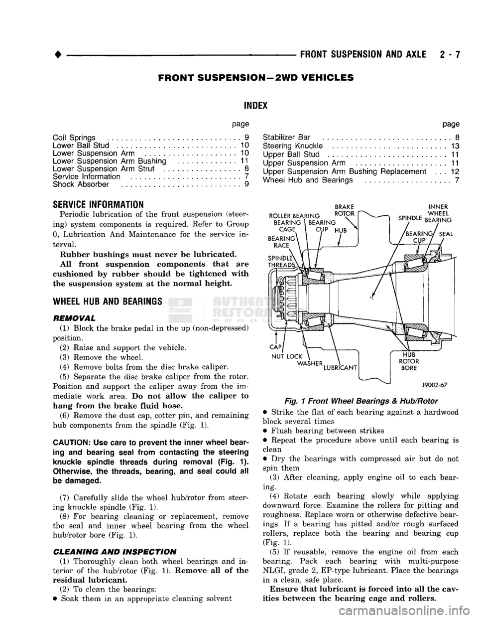
(6) Remove the dust cap, cotter pin, and remaining
hub components from the spindle (Fig. 1).
CAUTION:
Use care
to
prevent
the
inner wheel bear
ing
and
bearing seal from contacting
the
steering
knuckle spindle threads during removal
(Fig. 1).
Otherwise,
the
threads, bearing,
and
seal could
all
be damaged.
(7) Carefully slide the wheel hub/rotor from steer
ing knuckle spindle (Fig. 1).
(8) For bearing cleaning or replacement, remove
the seal and inner wheel bearing from the wheel
hub/rotor bore (Fig. 1).
CLEANING AND INSPECTION (1) Thoroughly clean both wheel bearings and in
terior of the hub/rotor (Fig. 1). Remove all of the residual lubricant.
(2) To clean the bearings:
• Soak them in an appropriate cleaning solvent
BRAKE
INNER
Fig.
1 Front
Wheel
Bearings
&
Hub/Rotor
• Strike the flat of each bearing against a hardwood
block several times • Flush bearing between strikes
• Repeat the procedure above until each bearing is
clean
• Dry the bearings with compressed air but do not spin them
(3) After cleaning, apply engine oil to each bear
ing. (4) Rotate each bearing slowly while applying
downward force. Examine the rollers for pitting and
roughness. Replace worn or otherwise defective bear
ings.
If a bearing has pitted and/or rough surfaced
rollers, replace both the bearing and bearing cup (Fig. 1).
(5) If reusable, remove the engine oil from each
bearing. Pack each bearing with multi-purpose NLGI, grade 2, EP-type lubricant. Place the bearings
in a clean, safe place.
Ensure that lubricant is forced into all the cav
ities between the bearing cage and rollers.
Page 85 of 1502
2
- 32
FRONT
SUSPENSION
AND
AXLE
• (5) Disconnect flexible brake fluid hose fittings at
the frame crossmember. Plug the hoses at the fit
tings.
(6) Remove the shock absorber lower nut and stud
from the axle shaft tube bracket. Remove the nuts and disconnect the stabilizer bar links from the
spring brackets.
(7) Disconnect the vacuum hoses and wiring con
nections from the shift motor housing.
(8) Remove nuts and the washers from the spring
U-bolts. Remove the complete front axle from the ve
hicle.
INSTALLATION
(1) Position the front axle under the front of the
vehicle with the axle spring pads under the springs.
Place the spring brackets over the springs. Make sure the stabilizer bar link bolt holes face toward the
rear of the vehicle.
(2) Install the spring U-bolts, washers and nuts.
Refer to Front Suspension — 4WD Vehicles within
this group. (3) Install the shock absorber. Refer to Front Sus
pension — 4WD Vehicles within this group. (4) Connect the stabilizer bar links to the spring
brackets. Refer to Front Suspension-4WD Vehicles
within this group.
(5) Remove plugs and connect the brake hose fit
tings.
Refer to Group 5, Brakes. (6) Connect the drag-link ball stud to the steering
knuckle arm. Refer to Group 19, Steering. (7) Connect the drive shaft to the pinion yoke with
the installation reference marks aligned. Install the
washers and the nuts and tighten to 19 N*m (14 ft. lbs.) torque.
(8) Connect the vacuum hoses and wiring connec
tions to the shift motor housing. (9) Remove the supports, lower the vehicle and re
move the block from the brake pedal.
(10) Raise the vehicle.
• Bleed and adjust the brakes
• Lubricate all the ball stud fittings
• Inspect the differential housing lubricant level. Re
fer to Group 0, Lubrication and Maintenance. (11) Lower the vehicle and test the axle and sus
pension operation.
DIFFERENTIAL
DISASSEMBLY
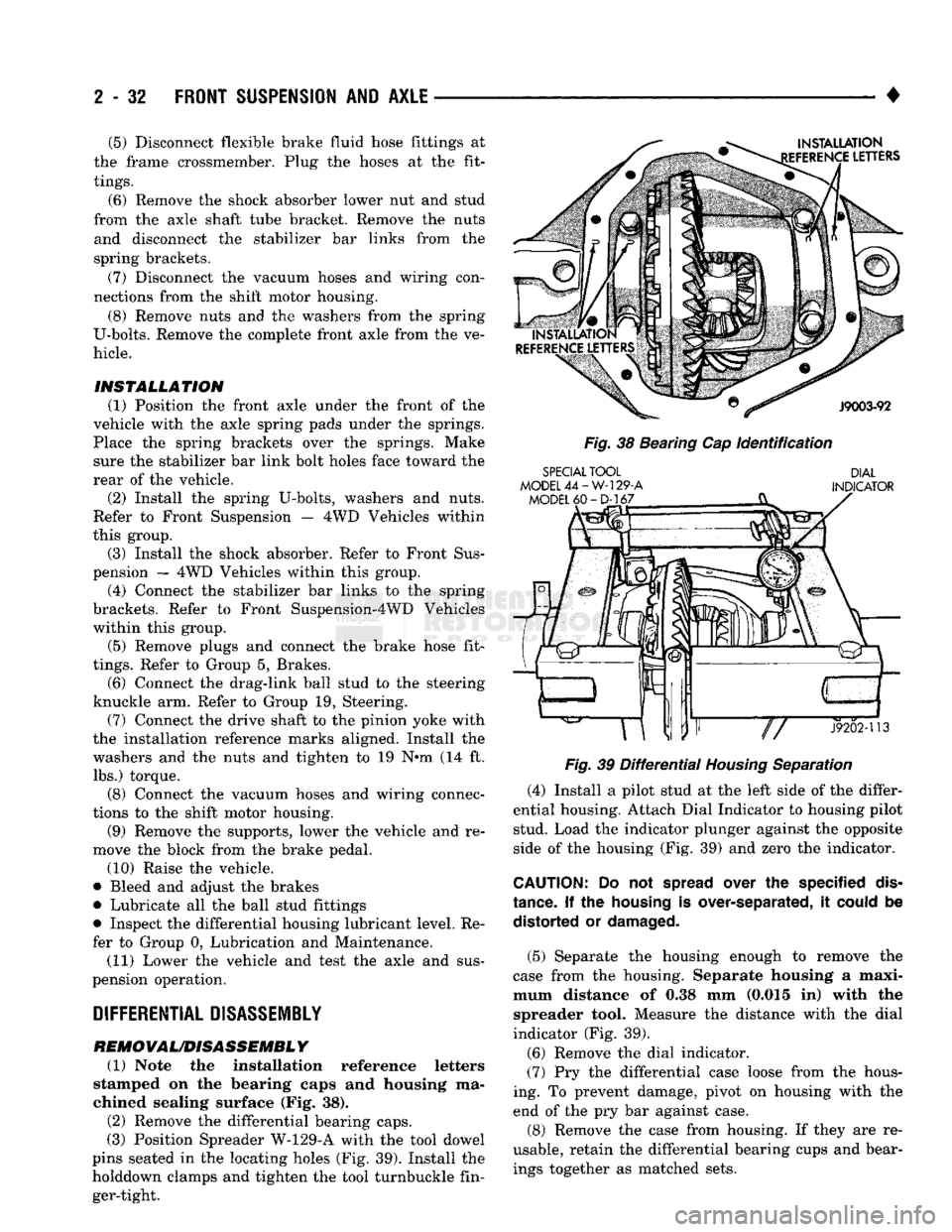
REMOVAL/DISASSEMBLY (1) Note the installation reference letters
stamped on the bearing caps and housing ma
chined sealing surface (Fig. 38). (2) Remove the differential bearing caps.
(3) Position Spreader W-129-A with the tool dowel
pins seated in the locating holes (Fig. 39). Install the
holddown clamps and tighten the tool turnbuckle fin ger-tight.
INSTALLATION
EFERENCE
LETTERS
J9003-92
Fig.
38 Bearing Cap
Identification
SPECIAL
TOOL
MODEL
44-W-129-A
MODEL
60-D-167
DIAL
INDICATOR
«ar"P—
J9202-113
Fig.
39
Differential
Housing
Separation
(4) Install a pilot stud at the left side of the differ
ential housing. Attach Dial Indicator to housing pilot stud. Load the indicator plunger against the opposite
side of the housing (Fig. 39) and zero the indicator.
CAUTION:
Do not
spread
over the specified
dis
tance.
If the
housing
is over-separated, it
could
be distorted or
damaged.
(5) Separate the housing enough to remove the
case from the housing. Separate housing a maxi
mum distance of 0.38 mm (0.015 in) with the spreader tool. Measure the distance with the dial
indicator (Fig. 39).
(6) Remove the dial indicator.
(7) Pry the differential case loose from the hous
ing. To prevent damage, pivot on housing with the end of the pry bar against case.
(8) Remove the case from housing. If they are re
usable, retain the differential bearing cups and bear ings together as matched sets.
Page 112 of 1502
•
TAPERED
BUSHING
J9202-53
Fig.
32 Tapered
Bushing
Installation
J9202-52
Fig.
33
Lower
King
Pin and Retainer
Installation
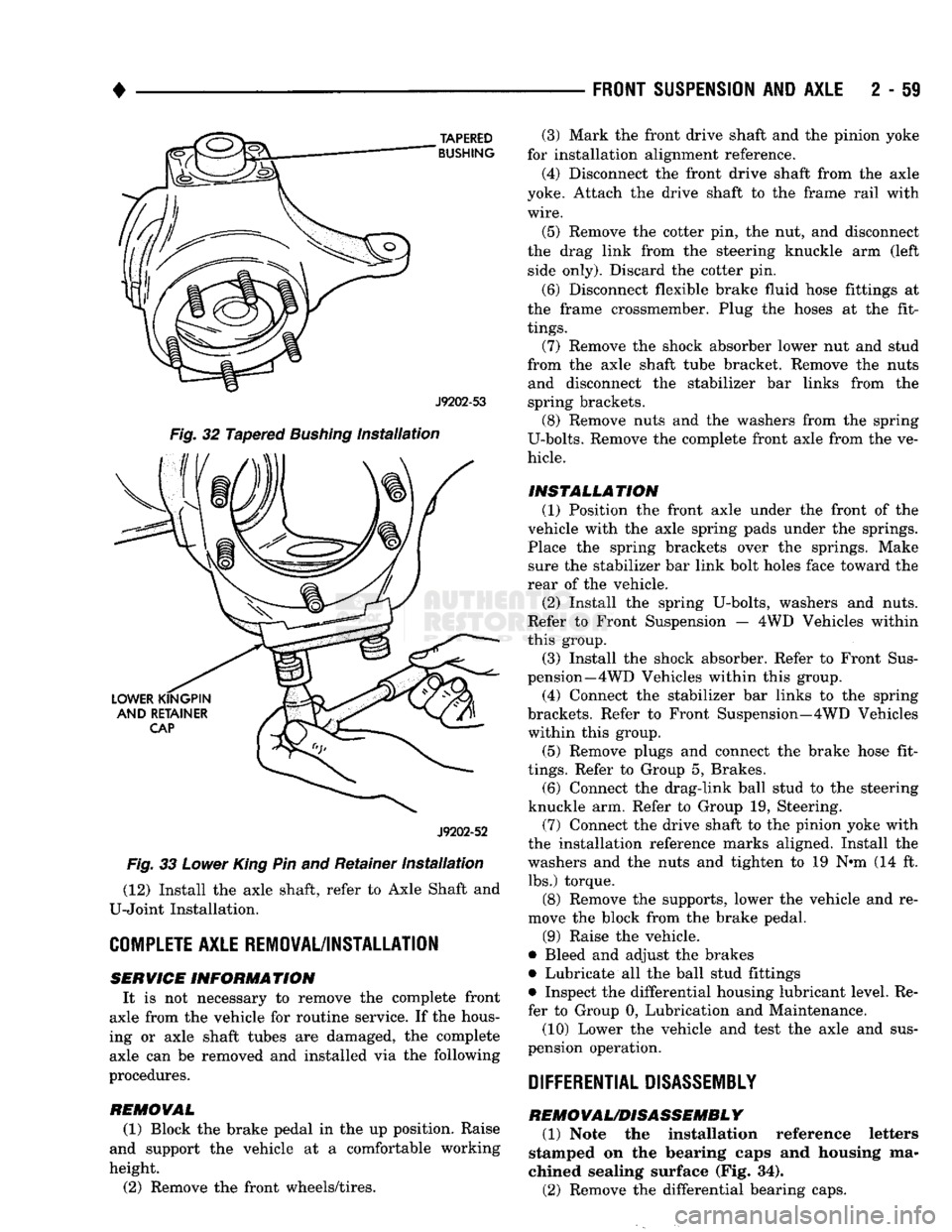
(12) Install the axle shaft, refer to Axle Shaft and
U-Joint Installation.
COMPLETE
AXLE REMOVAL/INSTALLATION SERVICE
INFORMATION
It is not necessary to remove the complete front
axle from the vehicle for routine service. If the hous
ing or axle shaft tubes are damaged, the complete axle can be removed and installed via the following
procedures.
REMOVAL
(1) Block the brake pedal in the up position. Raise
and support the vehicle at a comfortable working
height.
(2) Remove the front wheels/tires.
FRONT SUSPENSION
AND
AXLE
2 - 59
(3) Mark the front drive shaft and the pinion yoke
for installation alignment reference.
(4) Disconnect the front drive shaft from the axle
yoke. Attach the drive shaft to the frame rail with
wire.
(5) Remove the cotter pin, the nut, and disconnect
the drag link from the steering knuckle arm (left side only). Discard the cotter pin.
(6) Disconnect flexible brake fluid hose fittings at
the frame crossmember. Plug the hoses at the fit
tings.
(7) Remove the shock absorber lower nut and stud
from the axle shaft tube bracket. Remove the nuts and disconnect the stabilizer bar links from the
spring brackets. (8) Remove nuts and the washers from the spring
U-bolts. Remove the complete front axle from the ve
hicle.
INSTALLATION (1) Position the front axle under the front of the
vehicle with the axle spring pads under the springs.
Place the spring brackets over the springs. Make sure the stabilizer bar link bolt holes face toward the
rear of the vehicle.
(2) Install the spring U-bolts, washers and nuts.
Refer to Front Suspension — 4WD Vehicles within
this group. (3) Install the shock absorber. Refer to Front Sus
pension—4 WD Vehicles within this group.
(4) Connect the stabilizer bar links to the spring
brackets. Refer to Front Suspension—4WD Vehicles within this group.
(5) Remove plugs and connect the brake hose fit
tings.
Refer to Group 5, Brakes. (6) Connect the drag-link ball stud to the steering
knuckle arm. Refer to Group 19, Steering. (7) Connect the drive shaft to the pinion yoke with
the installation reference marks aligned. Install the
washers and the nuts and tighten to 19 N-m (14 ft. lbs.) torque.
(8) Remove the supports, lower the vehicle and re
move the block from the brake pedal.
(9) Raise the vehicle.
• Bleed and adjust the brakes
• Lubricate all the ball stud fittings
• Inspect the differential housing lubricant level. Re
fer to Group 0, Lubrication and Maintenance.
(10) Lower the vehicle and test the axle and sus
pension operation.
DIFFERENTIAL DISASSEMBLY
REMOVAL/DISASSEMBLY
(1) Note the installation reference letters
stamped on the bearing caps and housing ma
chined sealing surface (Fig. 34).
(2) Remove the differential bearing caps.
Page 140 of 1502
•
REAR
SUSPENSION
AND
AXLE
3 - 11 8 3/8 and 9 1/4
AXLE
INDEX
page
Axle Shaft, Seal
and
Bearing Service
......... 11
Complete Axle Removal/Installation
16
Differential
Service
16
Information
11
INFORMATION
The 8 3/8 and 9 1/4 axle (Fig. 1) housing consist of
a cast iron center section. They also have two steel
axle shaft tubes that are pressed into and welded to
the differential housing. The removable, stamped steel cover provides a
means for inspection and service without removing
the complete axle from the vehicle.
LUBRICANT
Multi-purpose, hypoid gear lubricant should be
used for 8 3/8 and 9 1/4 axles. The lubricant should
have MIL-L-2105C and API GL 5 quality specifica
tions.
MOPAR® Hypoid Gear Lubricant conforms to
both of these specifications.
Refer to Group 0, Lubrication and Maintenance for
additional information.
CAUTION:
If a
rear axle
is
submerged
in
water,
the
axle lubricant must
be
replaced immediately.
DRAIN
AND
REFILL
(1) Drive the vehicle until the gear lubricant
reaches normal operating temperature.
(2) Raise and support the vehicle.
(3) Remove the lubricant fill hole plug from the
differential housing cover.
(4) Remove the differential housing cover. Allow
the original lubricant to completely drain from the
housing and axle shaft tubes. (5) With standard differential, clean the differen
tial and the housing cavity with a flushing oil (or light engine oil). This will remove the residual lubri
cant and foreign matter.Do not use water, steam,
kerosene or gasoline for flushing.
CAUTION:
DO NOT
FLUSH
Sure-Grip differentials.
Sure-Grip
differentials
may be
cleaned only
by
wip
ing
with
clean,
lint-free
cloths.
(6)
Scrape the residual sealant from the housing
and cover mating surfaces. Clean the mating sur
faces with mineral spirits. Apply a bead of MOPAR® Silicone Rubber Sealant on the housing cover (Fig.
2).
Allow the sealant to cure for a few minutes.
page
Lubricant
11
Pinion Depth Measurement
and
Adjustment
with
Gauge
Set 20
Pinion
Seal
Replacement
14
Install the housing cover within 5 minutes af
ter applying the sealant. If not installed, the sealant must be removed and another bead ap
plied. (7) Install the cover on the differential. Install the
identification tag. Tighten the cover bolts to 47 N#m (35 ft. lbs.) torque.
CAUTION:
Overfilling
the
differential
can
result
in
the lubricant foaming
and
overheating.
(8) Refill the differential with the specified quan
tity of MOPAR® Hypoid Gear Lubricant. With Sure- Grip differentials, add a container of MOPAR®
Hypoid Gear Lubricant Additive.
(9) Install the fill hole plug.
(10) Road test the vehicle.
AXLE
SHAFT, SEAL AND BEARING
SERVICE
CAUTION:
When rear axle service
is
necessary, both rear wheels must
be
raised
off the
surface
so
that
they
are
free
to
rotate.
Be
cautious when
the
tires
are
being rotated
by the
engine
or by
other
means.
CAUTION:
If
equipped
with
a
Sure-Grip
differential,
do
not
rotate
either
axle shaft unless both
are
prop
erly
in-place. Rotation
of one
axle shaft without
the
other being installed
can
result
in
misalignment
of
the side gears/splines. This
will
necessitate side
gear
re-alignment before
the
axle shaft
can be in
stalled.
AXLE SHAFT REMOVAL
(1) Raise and support the vehicle.
(2) Remove the wheel.
(3) Remove the brake drum.
(4) Clean all the foreign material from housing
cover area.
(5) Loosen the housing cover bolts. Drain the lubri
cant from the housing. Remove the housing cover.
(6)
Rotate the differential case so the pinion mate
gear shaft lock screw is accessible. Remove the lock screw and the pinion mate gear shaft from the case (Fig. 3).
Page 178 of 1502
REAR
SUSPENSION
AND
AXLE
3 - 51
TRAC-LOK
DIFFERENTIAL
SERVICE
INFORMATION
Model
60 rear
axles equipped
with
Trac-Lok
differ
ential are optionally available for Ram Truck vehi
cles.
DIFFERENTIAL
NOISE
Noise complaints involving Trac-Lok should be
evaluated to determine the source of the noise. If a noise occurs while the vehicle is turning, the proba
ble cause is incorrect or insufficient gear lubricant. Replace the axle gear lubricant and add MOPAR Hy
poid Gear Lubricant Additive. If the chatter persists, clutch disc damage could have occurred.
WARNING: WHEN SERVICING VEHICLES
WITH
A
TRAC-LOK DIFFERENTIAL,
DO NOT
USE
THE EN
GINE
TO
ROTATE
THE
AXLE
AND
WHEELS.
BOTH
REAR
WHEELS MUST
BE
RAISED, FROM
THE
SUR
FACE
AND THE
VEHICLE SUPPORTED. TRAC-LOK
CAN EXERT ENOUGH DRIVING FORCE
TO
CAUSE
THE VEHICLE
TO
MOVE.
(4) Place a block of wood that is 2 inches high and
a minimum of 3 inches wide in front of one of the
front tires.
(5) With a gradual throttle opening, attempt to
slowly drive the vehicle over the block of wood.
(6) If the Kraft paper slips out before the front
wheel moves over the block of wood; reposition the vehicle so paper and board are under the opposite
rear wheel. Attempt to drive over the block of wood
the second time.
(7) If the front wheel moves over the block of wood,
the axle can be considered to be functioning nor mally.
LUBRICANTS
The lubricant recommended for Trac-Lok differen
tial is API grade GL 5. A container of Trac-Lok Lu
bricant (friction modifier) should be added after service. Refer to Group 0, Lubrication and Maintenance for
additional information.
DIFFERENTIAL
TEST
(1) Drive the vehicle to thoroughly warm up the
lubricant in the rear axle. (2) Place a large piece of Kraft paper over a
smooth Formica board.
(3) Drive the vehicle over the Formica board until
one rear wheel/tire is in the center of the board and
paper.
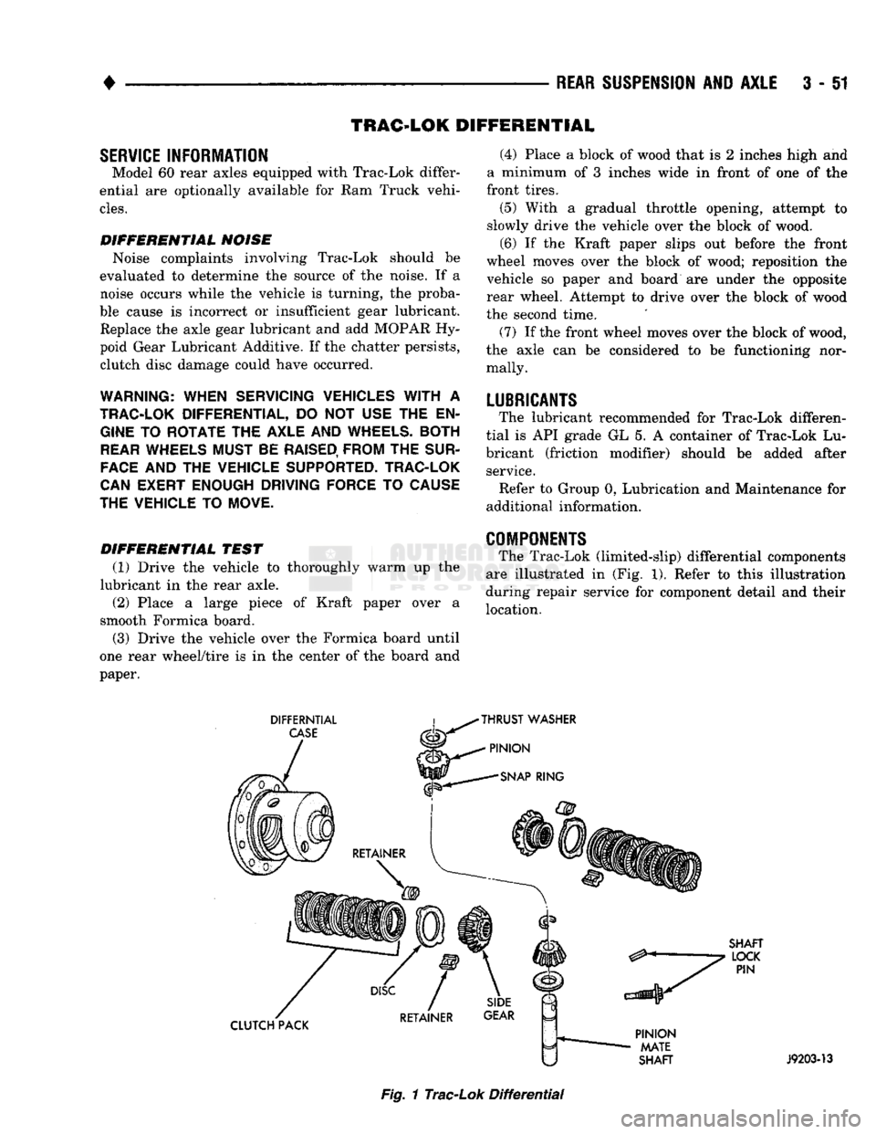
COMPONENTS
The Trac-Lok (limited-slip) differential components
are illustrated in (Fig. 1). Refer to this illustration
during repair service for component detail and their
location.
DIFFERNTIAL
CASE
THRUST
WASHER
PINION
SNAP
RING
SHAFT
LOCK
PIN
CLUTCH PACK
PINION
MATE
SHAFT
J9203-13
Fig.
1
Trac-Lok
Differential
Page 183 of 1502
3
- 56
REAR SUSPENSION
AND
AXLE
CLUTCH
PLATES
J9203-72
BUTTON
HALF
FLANGE
HALF
Fig.
2
Case
Marked
(7)
If the front wheel moves over the block of wood,
the axle can be considered to be functioning normally.
LUBRICANTS
The lubricant recommended for Power-Lok differ
ential is API grade GL 5. A container of Trac-Lok
Lubricant (friction modifier) should be added after
service. Refer to Group 0, Lubrication and Maintenance for
additional information.
FLANGE
HALF
CLUTCH
RING
J9203-73
Fig.
3
Cover
Half
Removal
DISASSEMBLY
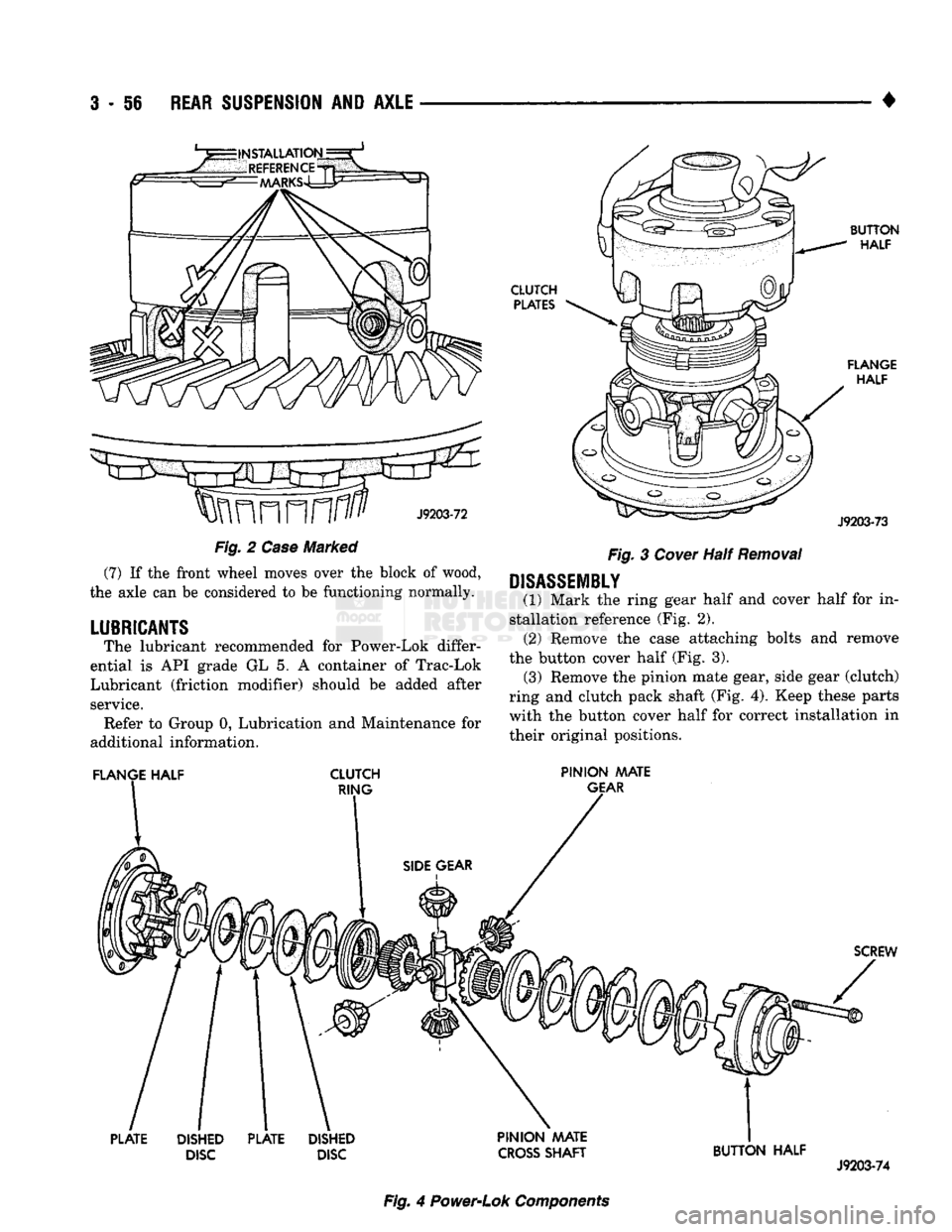
(1) Mark the ring gear half and cover half for in
stallation reference (Fig. 2). (2) Remove the case attaching bolts and remove
the button cover half (Fig. 3). (3) Remove the pinion mate gear, side gear (clutch)
ring and clutch pack shaft (Fig. 4). Keep these parts with the button cover half for correct installation in
their original positions.
PINION MATE
GEAR
SCREW
PLATE
DISHED
DISC
PLATE
DISHED
DISC PINION AAATE
CROSS
SHAFT
BUTTON HALF
J9203-74
Fig.
4
Power-Lok
Components
Page 216 of 1502
•
BRAKES
5 - 29 presses the outboard shoe lining against the opposite
side of the rotor to complete braking action.
The application or release of fluid pressure causes
only a very slight movement of the caliper and pis
ton. At brake release, the piston and caliper return
to the non-applied position.
The brakeshoes do not retract an appreciable dis
tance from the rotor. The minimal running clearance
between the lining and rotor provides improved re sponse and reduced pedal travel. It also helps in pre
venting dirt and foreign material from lodging
between the shoe and rotor surfaces.
DISC
BRAKE
LINING WEAR COMPENSATION
Normal lining wear is compensated for by extension
of the caliper piston and by lateral movement of the cal
iper in the adapter. Piston position is also determined
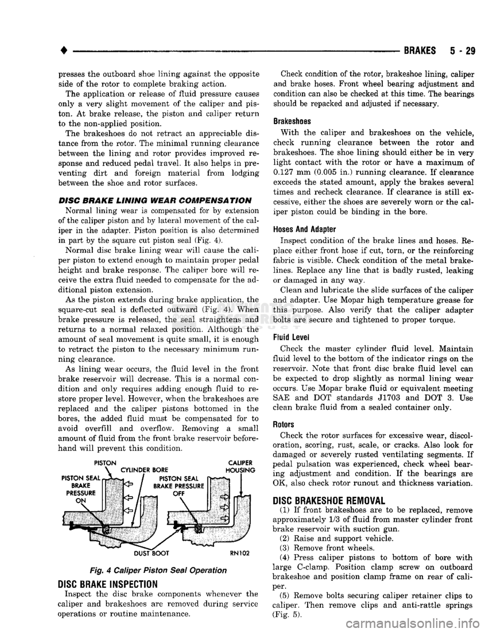
in part by the square cut piston seal (Fig. 4).
Normal disc brake lining wear will cause the cali
per piston to extend enough to maintain proper pedal height and brake response. The caliper bore will receive the extra fluid needed to compensate for the ad
ditional piston extension.
As the piston extends during brake application, the
square-cut seal is deflected outward (Fig. 4). When
brake pressure is released, the seal straightens and
returns to a normal relaxed position. Although the amount of seal movement is quite small, it is enough
to retract the piston to the necessary minimum run
ning clearance.
As lining wear occurs, the fluid level in the front
brake reservoir will decrease. This is a normal con dition and only requires adding enough fluid to restore proper level. However, when the brakeshoes are
replaced and the caliper pistons bottomed in the
bores,
the added fluid must be compensated for to avoid overfill and overflow. Removing a small
amount of fluid from the front brake reservoir before
hand will prevent this condition.
PISTON CALIPER
DUST BOOT
RN102
Fig.
4 Caliper
Piston
Seal
Operation
DISC
BRAKE INSPECTION
Inspect the disc brake components whenever the
caliper and brakeshoes are removed during service
operations or routine maintenance. Check condition of the rotor, brakeshoe lining, caliper
and brake hoses. Front wheel bearing adjustment and
condition can also be checked at this time. The bearings
should be repacked and adjusted if necessary.
Brakeshoes
With the caliper and brakeshoes on the vehicle,
check running clearance between the rotor and
brakeshoes. The shoe lining should either be in very light contact with the rotor or have a maximum of
0.127 mm (0.005 in.) running clearance. If clearance
exceeds the stated amount, apply the brakes several
times and recheck clearance. If clearance is still ex cessive, either the shoes are severely worn or the cal
iper piston could be binding in the bore.
Hoses
And Adapter Inspect condition of the brake lines and hoses. Re
place either front hose if cut, torn, or the reinforcing
fabric is visible. Check condition of the metal brake-
lines.
Replace any line that is badly rusted, leaking
or damaged in any way.
Clean and lubricate the slide surfaces of the caliper
and adapter. Use Mopar high temperature grease for
this purpose. Also verify that the caliper adapter
bolts are secure and tightened to proper torque.
Fluid Level Check the master cylinder fluid level. Maintain
fluid level to the bottom of the indicator rings on the
reservoir. Note that front disc brake fluid level can
be expected to drop slightly as normal lining wear occurs. Use Mopar brake fluid or equivalent meeting SAE and DOT standards J1703 and DOT 3. Use
clean brake fluid from a sealed container only.
Rotors
Check the rotor surfaces for excessive wear, discol
oration, scoring, rust, scale, or cracks. Also look for
damaged or severely rusted ventilating segments. If
pedal pulsation was experienced, check wheel bear ing adjustment and condition. If the bearings are OK, also check rotor runout and thickness variation.
DISC
BRAKESHOE
REMOVAL
(1) If front brakeshoes are to be replaced, remove
approximately 1/3 of fluid from master cylinder front
brake reservoir with suction gun. (2) Raise and support vehicle.
(3) Remove front wheels.
(4) Press caliper pistons to bottom of bore with
large C-clamp. Position clamp screw on outboard
brakeshoe and position clamp frame on rear of cali
per. (5) Remove bolts securing caliper retainer clips to
caliper. Then remove clips and anti-rattle springs (Fig. 5).